Español
  pусский
  العربية
  Português
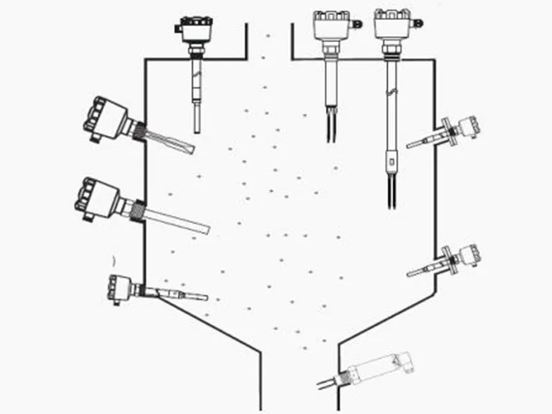
Selection and application of stainless steel housings for industrial instruments
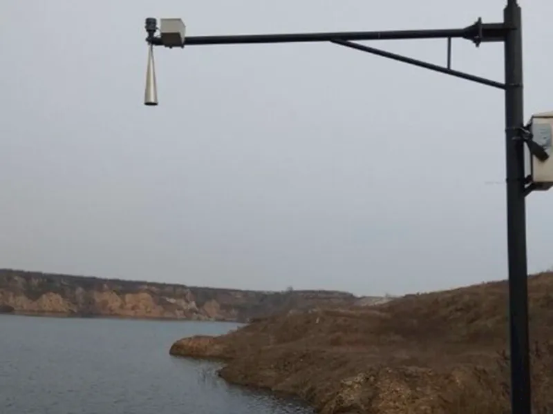
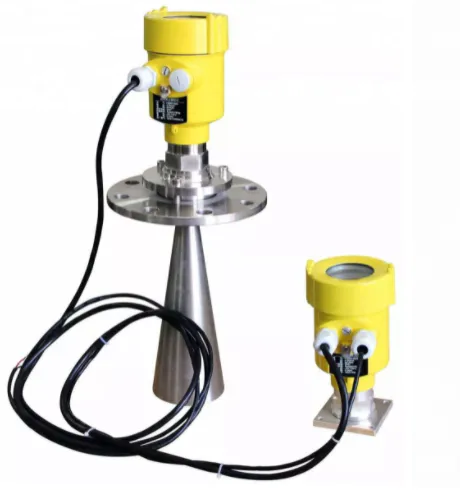
Research Scope of Insertion Electromagnetic Flow Meter
by:Kaidi Sensors
2022-08-31
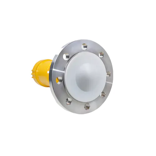
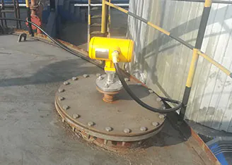
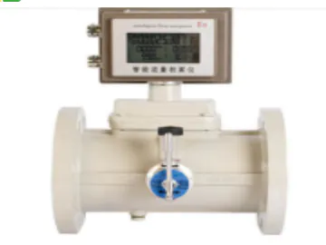
Abstract: The research scope information of the plug-in electromagnetic flowmeter is provided by the excellent flowmeter and flowmeter production and quotation manufacturers. 1.1 Definition of signal action range According to the working principle of plug-in electromagnetic flowmeter, the farther the area is from the electrode, the weaker the magnetic induction intensity; when it is far away to a certain distance, the electromotive force generated by the fluid cutting the magnetic induction line is so weak that it is not enough. Fluid will be tested. More flowmeter manufacturers choose models and price quotations. You are welcome to inquire. The following are the details of the research scope of the plug-in electromagnetic flowmeter. 1.1 Definition of signal action range According to the working principle of plug-in electromagnetic flowmeter, the farther the area is from the electrode, the weaker the magnetic induction intensity; when it is far away to a certain distance, the electromotive force generated by the fluid cutting the magnetic induction line is so weak that it is not enough. Affects fluid test results. Therefore, for large-diameter pipelines, the flow signal detected by the probe electrode of the plug-in electromagnetic flowmeter sensor is actually the electrical signal in a certain space area near the sensor probe in the pipeline under test, rather than covering the entire pipeline. Therefore, this paper makes a clear definition of the scope of the signal. The signal action range refers to a certain space area near the electrode, in which the electromotive force generated by the conductive fluid cutting the magnetic field line plays a decisive role in the flow detection result. 1.2 Definition of the equivalent radius R In the flow field, the stronger the signal, the easier it is to be received by the electrode. The size of the signal generated at each point in the field is related to the flow velocity through the point. As a result, the flow field distribution changes, so it can be seen that the electrodes are not equidistant to collect effective signals around them, that is, the actual signal range is an irregular area. For the convenience of research, the following method is used to define the equivalent signal range. A spherical area VR with radius R around the electrode makes it equivalent to the contribution of the actual signal range to the signal, that is, it satisfies the formula (1). (1) In formula (1), Π is the actual overall area where the fluid cuts the magnetic field lines in the flow field and contributes to the signal, VR is the area with the electrode as the center of the sphere, and its radius R is defined as the equivalent radius,Φ(x, y, z) is the signal contributed by the unit volume of the fluid in the flow space. As long as the equivalent radius R is determined, the equivalent signal action range VR can be characterized. 1.3 The research method of equivalent radius R According to the calculation formula of volume flow, it can be known: QV=AU (2) U in formula (2) refers to the surface average flow velocity of section A. The actual detected flow velocity during the measurement of the instrument should be the overall average flow velocity within the range of the signal. The conversion coefficient K of the instrument is obtained through the calibration of the standard device. The average velocity of the surface of the cross section (referred to as the minimum section), thereby calculating the flow value. Therefore, in the simulation, the average flow velocity in the signal action range can be replaced by the average flow velocity of the minimum cross-section. Through this principle, the signal action range can be solved and verified. 1.4 Analysis steps of equivalent radius R Regarding the determination of equivalent radius R, numerical simulation is carried out on the large-diameter pipeline inserted into the probe with FLUENT software. The steps are: ① Obtain the relationship between the radius r of different regions and the average flow velocity in the spherical area of the radius under a certain flow velocity U; ② Obtain the theoretical average flow velocity of the minimum cross-section according to the continuity equation; ③ Use the interpolation method Determine the equivalent radius R of the signal action range under the incoming flow velocity; ④ Repeat the simulation experiment by changing the incoming flow velocity. 2 Determination method of signal action range 2.1 Determination of computational domain In order to ensure the quality of the grid, the cylindrical two-electrode probe, which is widely used in engineering and has a relatively simple structure, is selected as the simulation object. The computational domain is shown in Figure 1. On the basis of ensuring the front and rear straight pipe sections, water at normal temperature and pressure is set as the flowing medium, the inlet boundary condition is the velocity inlet, the outlet boundary condition is the pressure outlet, and the standard k-ε model is selected as the turbulent flow model. The empirical constants C1ε, C2ε, C3ε is taken as 1.44, 1.92, and 0.09, respectively, and the turbulent kinetic energy and dissipation rate are taken as 1.0 and 1.3, respectively. According to the concept of signal action range, as long as the probe can detect the flow signal, indicating that the flow there must be within the range of the magnetic field, the average velocity in the calculation domain is: (3) In formula (3), Vr is the calculation area, u ( x, y, z) is the velocity function. Figure 1 Calculation domain of plug-in electromagnetic flowmeter The above is the whole content of this article. You are welcome to inquire about the flowmeter selection and quotation of our factory. 'The Research Scope of Insertion Electromagnetic Flow Meter'
Guangdong Kaidi Energy Technology Co., Ltd. has various branches in local businesses, servicing customers and helping to pull in traffic to those businesses.
Guangdong Kaidi Energy Technology Co., Ltd. works hard to enhance continuously our reputation for accessibility, professionalism, performance, and the depth and quality of our long-term consultative relationships with clients.
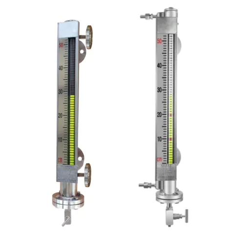
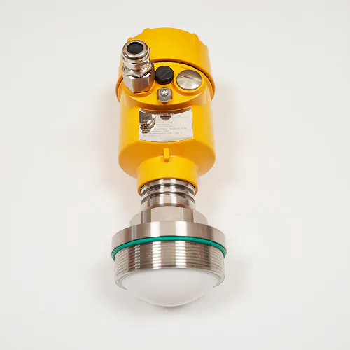
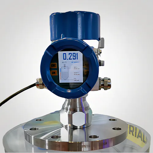
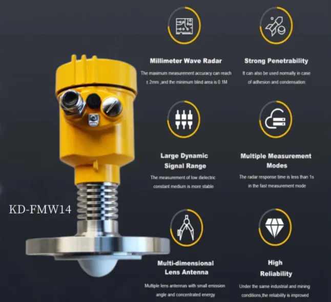
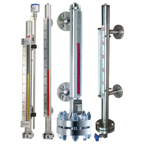
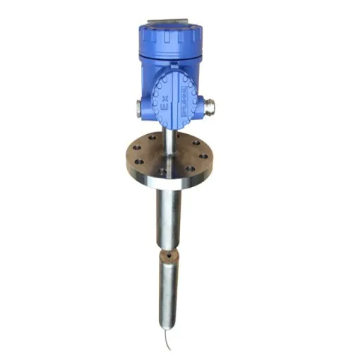
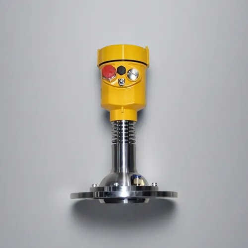
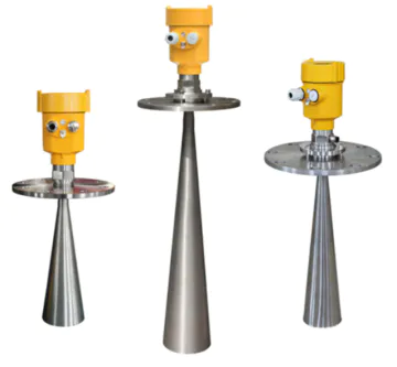
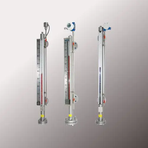
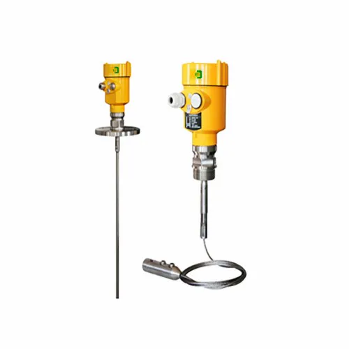
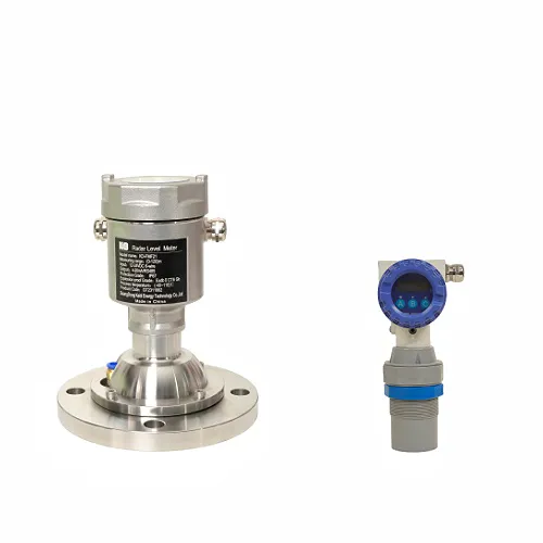
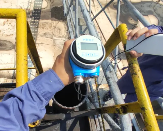
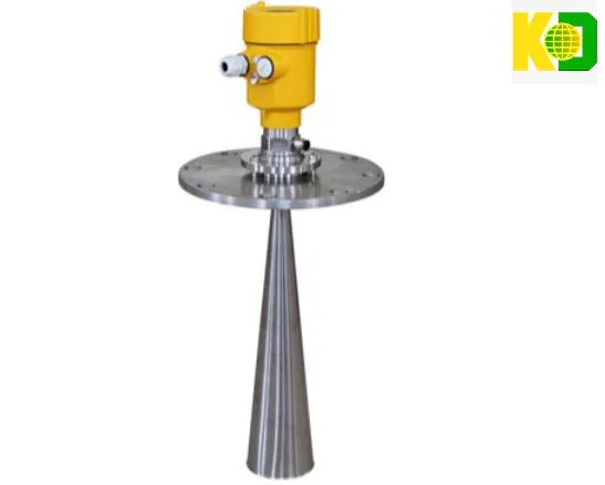
Visit Kaidi level indicator to find recent dynamics of level gauge and contact Guangdong Kaidi Energy Technology Co., Ltd. for the latest and most capable in global market.
Looking for Manufacturers in China? Then Guangdong Kaidi Energy Technology Co., Ltd. is the right choice. we are a well known customized level indicator level gauge Manufacturers and suppliers from China.
If Guangdong Kaidi Energy Technology Co., Ltd. added selling plans, offered more level gauge, and increased service regions, it would suit the needs of more users.
Guangdong Kaidi Energy Technology Co., Ltd. has various branches in local businesses, servicing customers and helping to pull in traffic to those businesses.
Guangdong Kaidi Energy Technology Co., Ltd. works hard to enhance continuously our reputation for accessibility, professionalism, performance, and the depth and quality of our long-term consultative relationships with clients.
Visit Kaidi level indicator to find recent dynamics of level gauge and contact Guangdong Kaidi Energy Technology Co., Ltd. for the latest and most capable in global market.
Looking for Manufacturers in China? Then Guangdong Kaidi Energy Technology Co., Ltd. is the right choice. we are a well known customized level indicator level gauge Manufacturers and suppliers from China.
If Guangdong Kaidi Energy Technology Co., Ltd. added selling plans, offered more level gauge, and increased service regions, it would suit the needs of more users.
Custom message
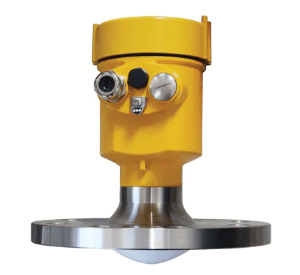
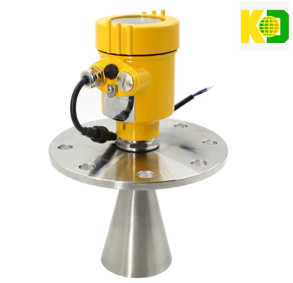
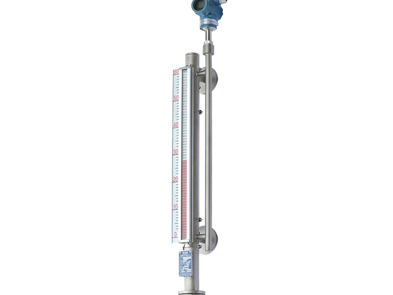
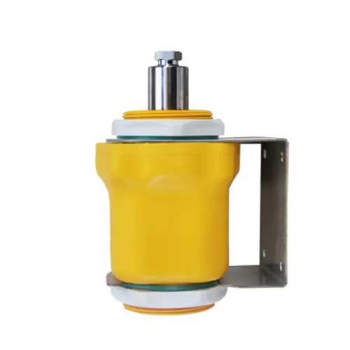
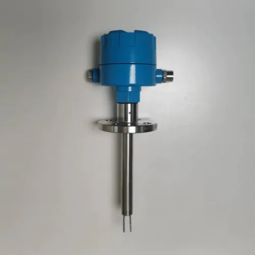
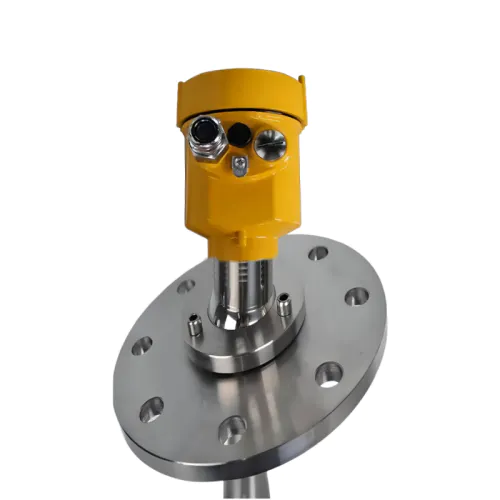
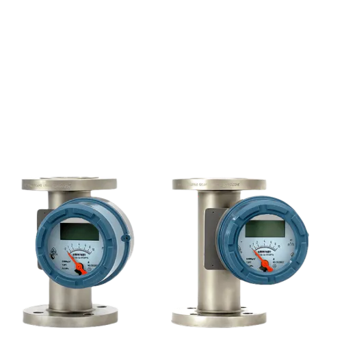
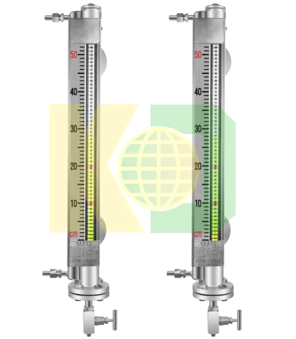
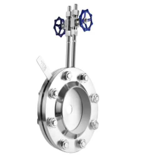
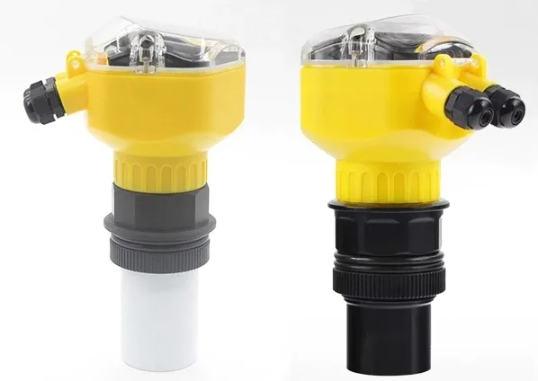
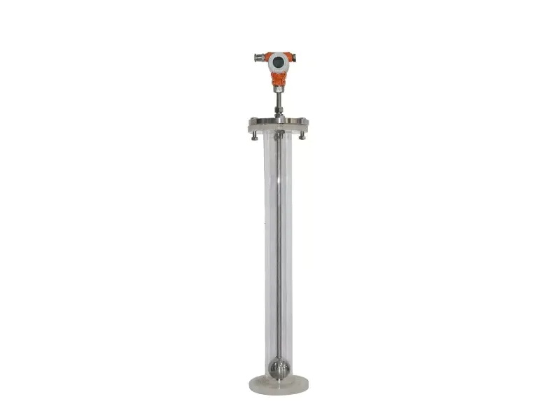
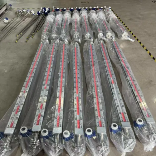
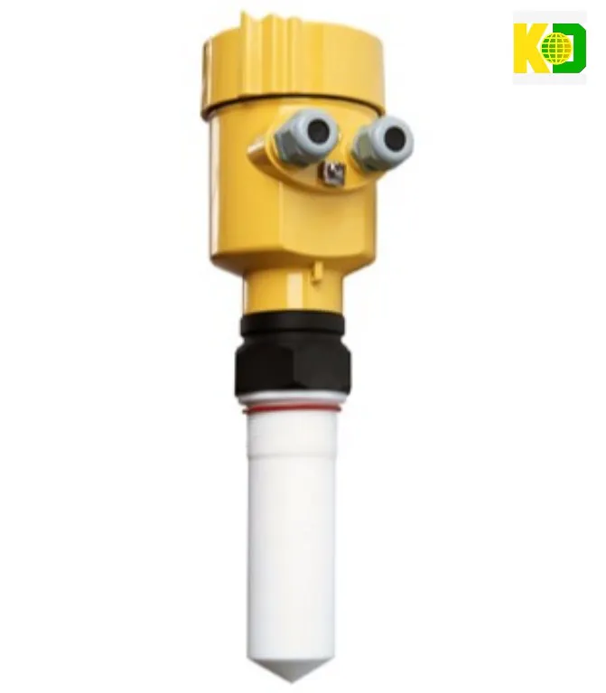
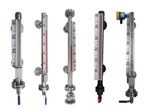
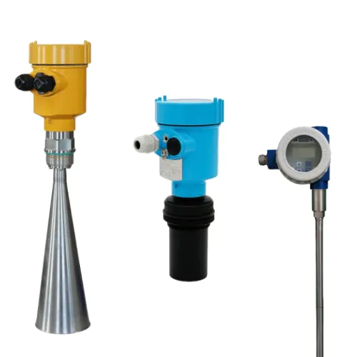
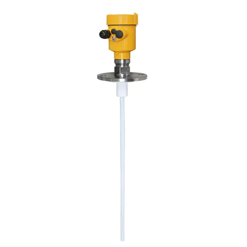
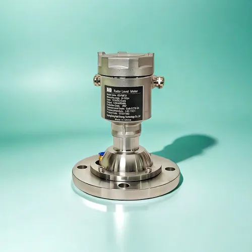
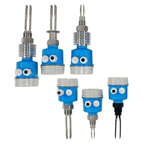
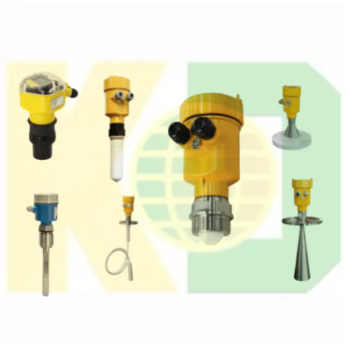
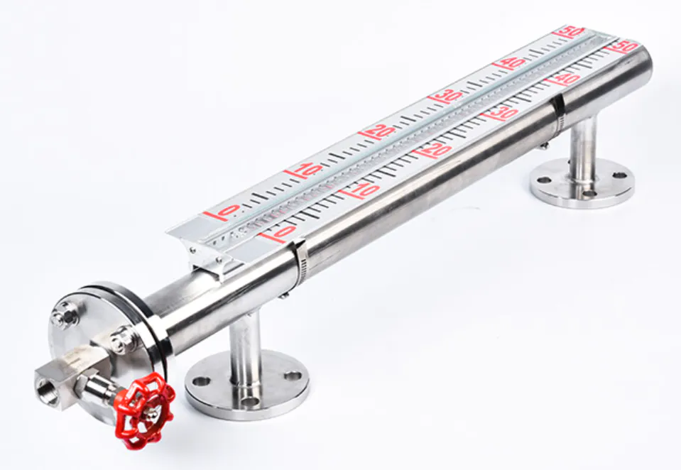
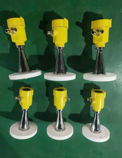
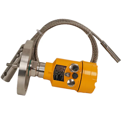
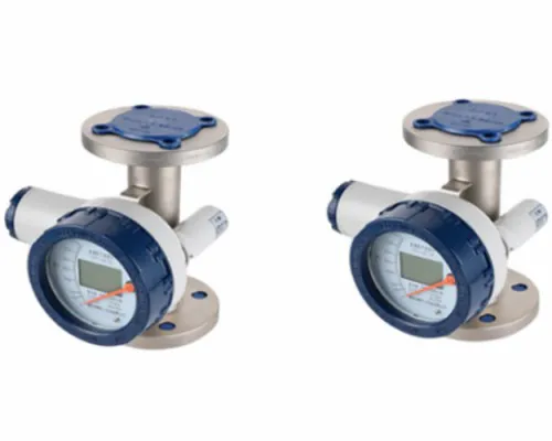
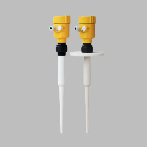
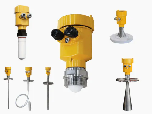
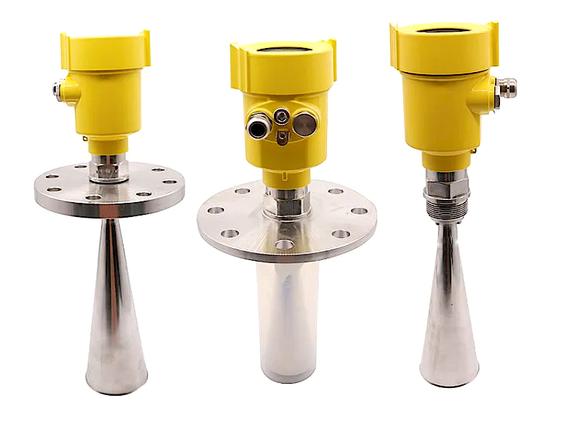
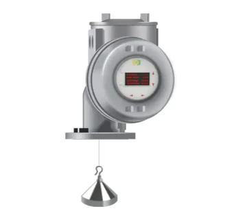
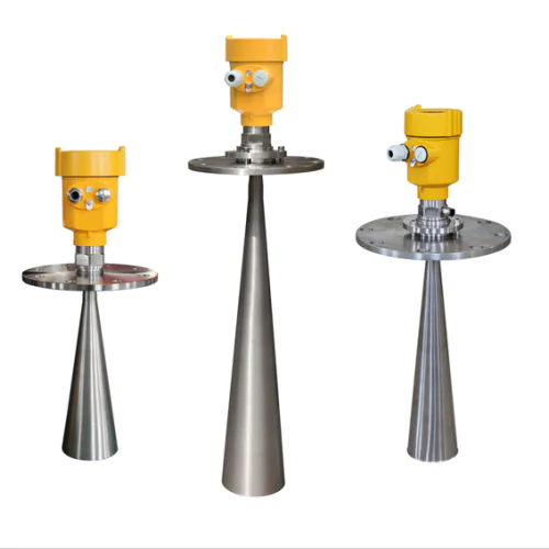
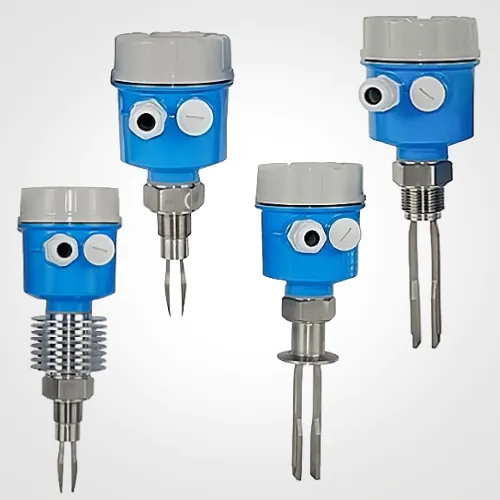
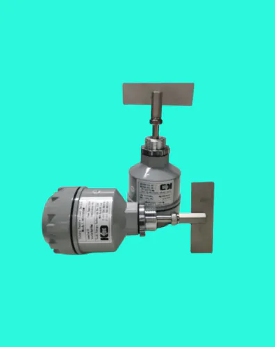
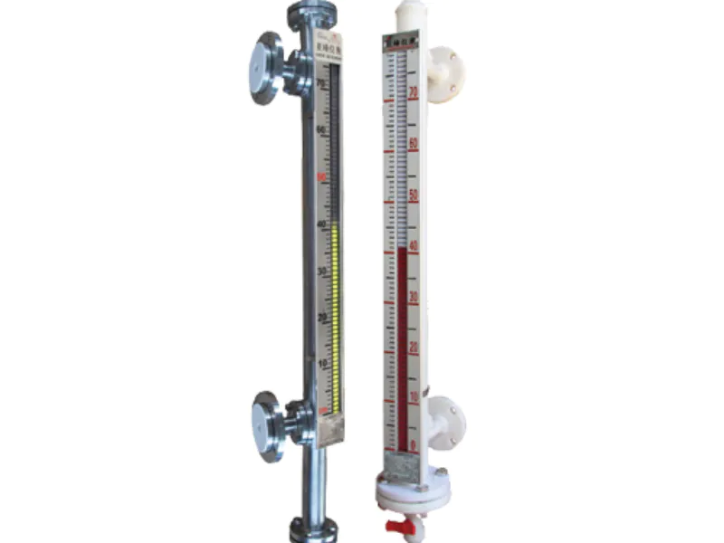
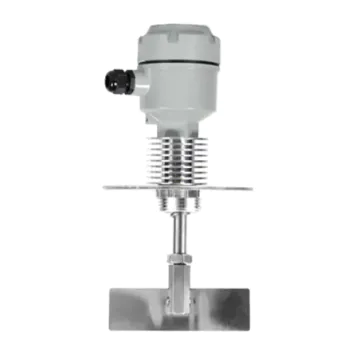
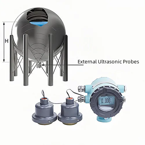
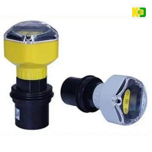
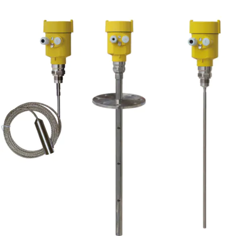
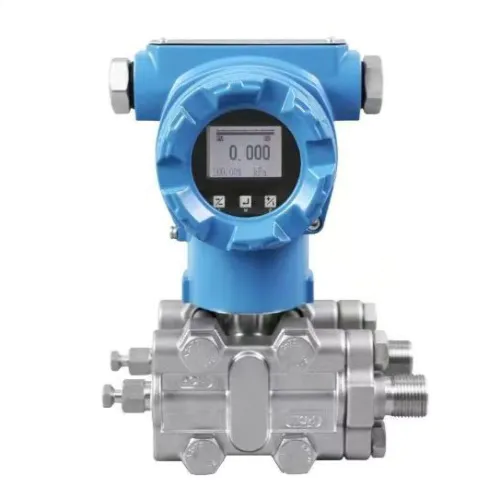
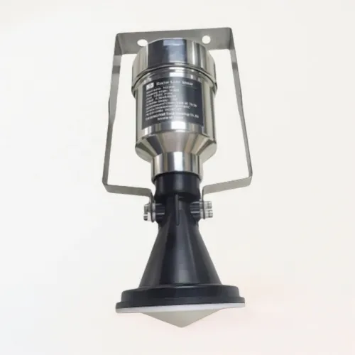
Related Products