 Español
  pусский
  العربية
  Português
BETTER TOUCH BETTER BUSINESS
Contact Sales at KAIDI.
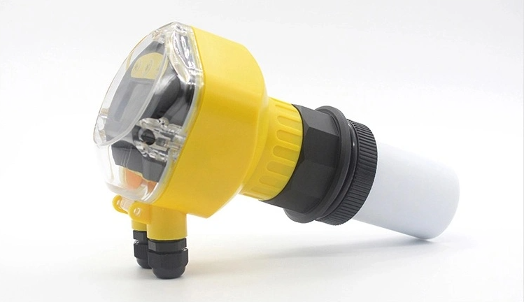
Calibration Method of Ultrasonic Level sensor under Different Errors
In liquid level measurement, ultrasonic Level sensor is a kind of non-contact material level measuring instrument that is widely used. However, in practical application, as temperature, humidity, dust, chemical composition of the measured liquid and other factors will affect the measurement accuracy of the ultrasonic Level sensor wholesale to varying degrees, it is necessary to master the calibration methods of different errors caused by different factors to achieve accurate measurement. Next, we will introduce the calibration methods and compensation measures of the ultrasonic Level sensor under different errors.

Transit time error and its calibration method
1. Transit time error
Transit time refers to the time required for upstream signals to be transmitted downstream. Since sound wave is an elastic Mechanical wave with longitudinal vibration, its propagation needs the help of molecular motion of the propagation medium. Due to factors such as absorption, scattering, and diffusion of sound waves in the propagation medium, sound intensity, pressure, and energy are weakened, resulting in sound attenuation. And the measurement of ultrasonic level transmitter needs to form a Infrasound reflection on the measured liquid level, which will also cause the attenuation of acoustic waves. Sound waves decay exponentially according to the propagation distance. When the liquid level height is different, the transmission distance of sound waves also varies, and the amplitude of the received waves will also have significant differences. The system starts timing when the probe emits ultrasound, and stops timing when the amplitude of the received signal exceeds the set threshold. When the liquid level height changes, the amplitude of the received signal will also change. When the liquid level is relatively low, the received signal amplitude is relatively small, and it may need to reach the threshold at the fourth peak; When the liquid level is relatively high, the amplitude of the received signal is relatively large, and the threshold may be reached by the third or even earlier. In this case, the time to stop timing is not fixed, and this uncertainty in time will inevitably bring errors to the measurement accuracy of the system. If the transit time error is applied to 1000m ³ The above oil storage tanks will produce large absolute error, so this error must be eliminated and calibrated.
2. Calibration method for gambling time error
Adding a time control circuit (TGC) is currently a relatively simple method to eliminate transit time errors. Using TGC circuit to compensate for the attenuation of sound waves during propagation, the amplitude of the received waves is basically consistent under various liquid level conditions, in order to minimize measurement errors as much as possible. Due to the need to predict the propagation time of sound waves at different liquid levels and the attenuation of sound waves within this distance, and then plot a curve based on the corresponding relationship between the two, and design a time gain control circuit that conforms to this curve equation, this method has significant limitations.
From the previous text, it can be seen that the important factors in the measurement of propagation time and attenuation are easily affected by the on-site environment and cannot match well with the pre planned curve. In fact, even if the fitted curve is very accurate, designing a TGC circuit that perfectly matches it is not easy. In this way, it is inevitable to introduce new errors in compensation.
To completely eliminate the transit time error, the signal transformation process of the receiving circuit is to preprocess the received signal, extract the envelope of the signal after DC detection, and perform differential processing on the envelope. Through the signal transformation process, regardless of the amplitude of the received signal, the peak of its envelope must be at the time center of the received signal, that is, at the zero crossing of the differential signal. Therefore, the stop timing signal generated by the zero crossing detection circuit must be at the time center of the echo signal and will not change due to the amplitude of the signal, thus completely eliminating the transit time error.

Reference Sound Velocity Accuracy Error and Its Calibration Method
We know that we know the speed of sound C and the transmission time T, according to the formula S=C × T/2, the distance S can be calculated. The propagation time of ultrasonic wave is the intermediate result of Level sensor measurement. When using ultrasonic Level sensor to measure liquid level, it is also necessary to know the propagation speed of ultrasonic wave in the air. Therefore, the accuracy of ultrasonic propagation speed has a great impact on the measurement accuracy of ultrasonic Level sensor.
In practice, there are two calibration methods for sound velocity accuracy errors: temperature compensation and real-time sound velocity compensation.
1. Temperature compensation
In the measurement process of ultrasonic Level sensor, there are many factors affecting the sound speed, including temperature, gas density, air pressure, humidity, suspended solids in the air, etc. Among these factors, temperature is the most important factor affecting the sound speed, other factors should also be considered, otherwise there will be deviation in the calibration of sound speed, which cannot meet the needs of high-precision measurement. Generally speaking, temperature compensation methods are only suitable for general applications that do not require high measurement accuracy.
2. Real time sound speed compensation
Practice has proven that, influenced by complex factors such as measurement environment and methods, it is necessary to introduce new errors regardless of the empirical formulas and data used to compensate for sound velocity. The method of using measured sound velocity for sound velocity compensation is currently considered the most reliable compensation method.
Install a baffle at the front end of the emission probe, which forms a fixed sound path interval with the probe. This structure is called a sound path frame. When the probe emits sound waves, the baffle can reflect a portion of the sound waves back to the probe. After receiving the reflected wave, the probe calculates the time from emission to reception and calculates the speed of sound.
Using the measured sound speed method for compensation, as the compensation sound speed is very similar to the environment where the measured sound wave propagation path is located, and the environmental impact is basically the same, the sound speed is usually relatively close, so this method is currently the most accurate sound speed correction method used. When using this method, in order to avoid Thermal expansion of the sound path holder due to changes in ambient temperature, which will change the sound path distance and affect the accuracy of measured sound velocity, the sound path holder should be made of materials with low temperature expansion coefficient.
System Error and Its Calibration Method
System error is mainly generated by system delay, and hardware circuit delay, interrupt response delay of microcontroller, probe response delay, etc. are the main sources of system delay. For the ultrasonic Level sensor working in the pulse emission state, after the single chip microcomputer sends the emission command each time, the transmission power amplifier circuit can reach the emission state only after a process of energy accumulation. At the same time, the piezoelectric ceramic in the probe also has a vibration starting process, and it also takes a certain time to reach the 40kHz vibration frequency. The timing starts from the issuance of the command, so the system delay must be considered and compensated in software.
In addition, when measuring liquid levels using ultrasound, the liquid level distance is from the front surface of the probe to the liquid level, and in fact, the acoustic center of the piezoelectric ceramic is not on its surface. Therefore, the distance from the probe surface to the acoustic center point can also cause system errors, which can be classified as time delay difference and corrected together.
For the ultrasonic Level sensor of the same model or batch, because the components, materials and processes used are the same, the system delay is also similar, and it is a relatively fixed value. Therefore, the system delay can be calibrated and corrected through fixed distance testing.
We are here to help you! If you close the chatbox, you will automatically receive a response from us via email. Please be sure to leave your contact details so that we can better assist

