Español
  pусский
  العربية
  Português
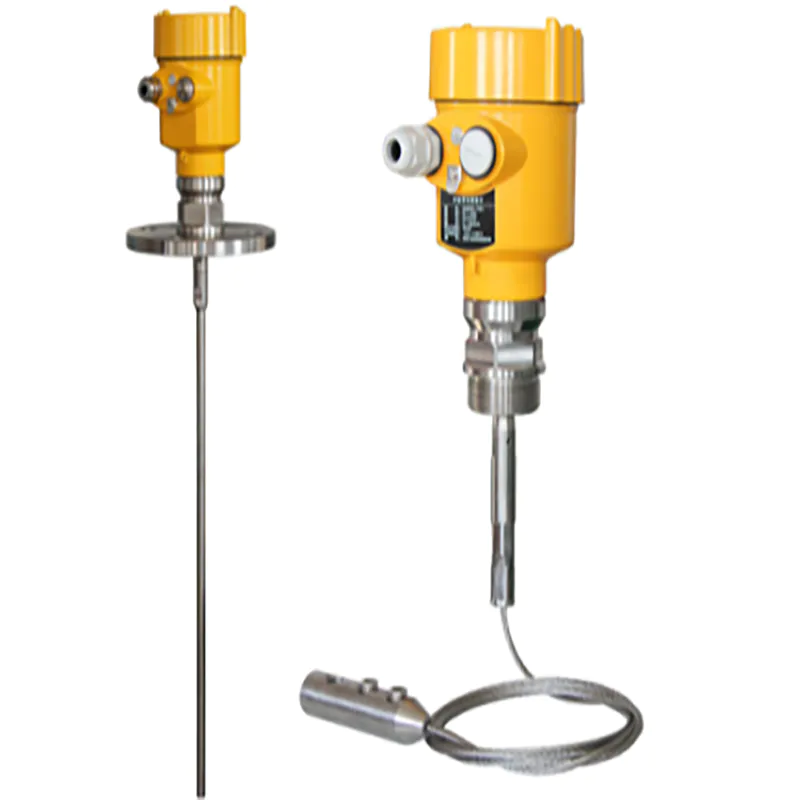
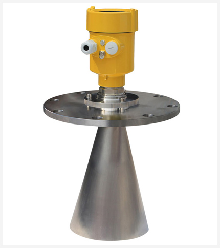
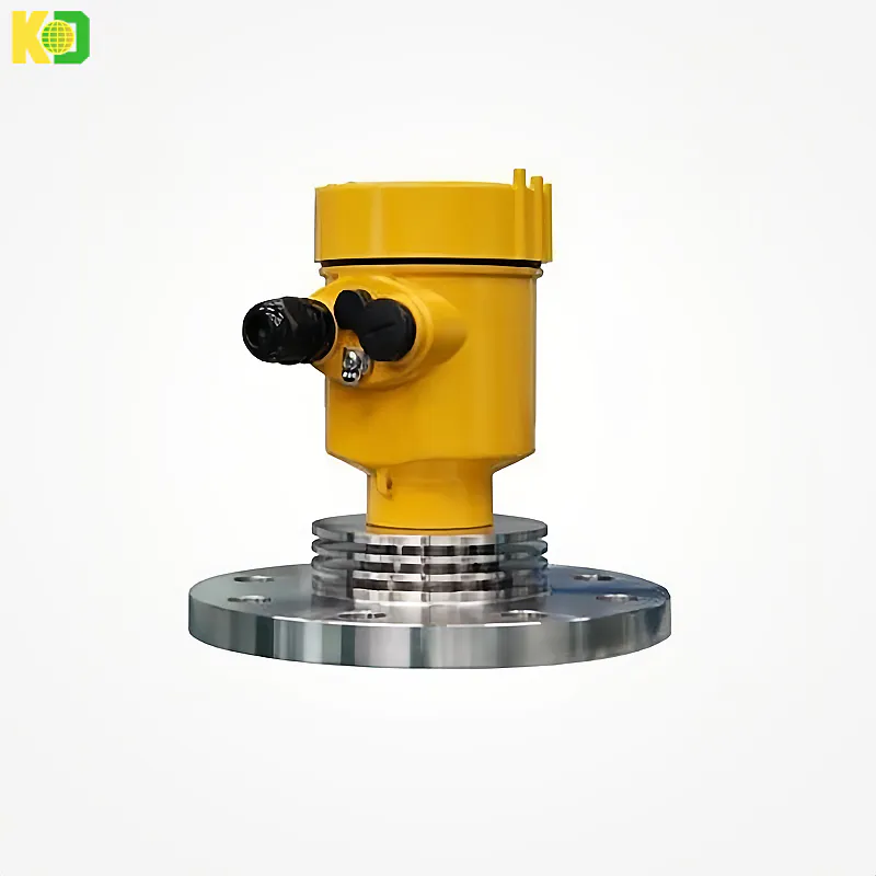
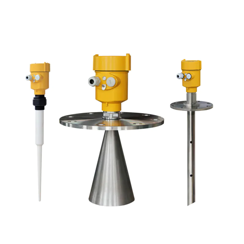
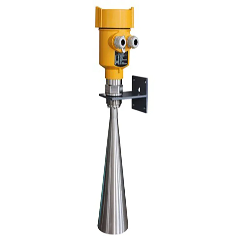
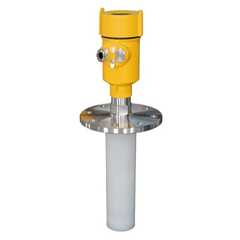
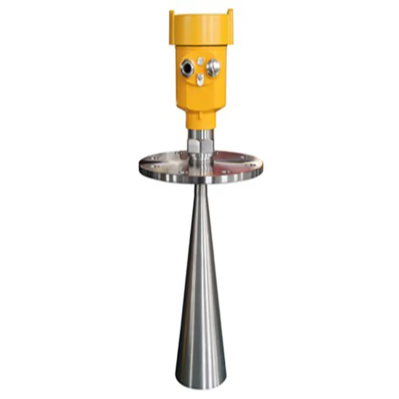
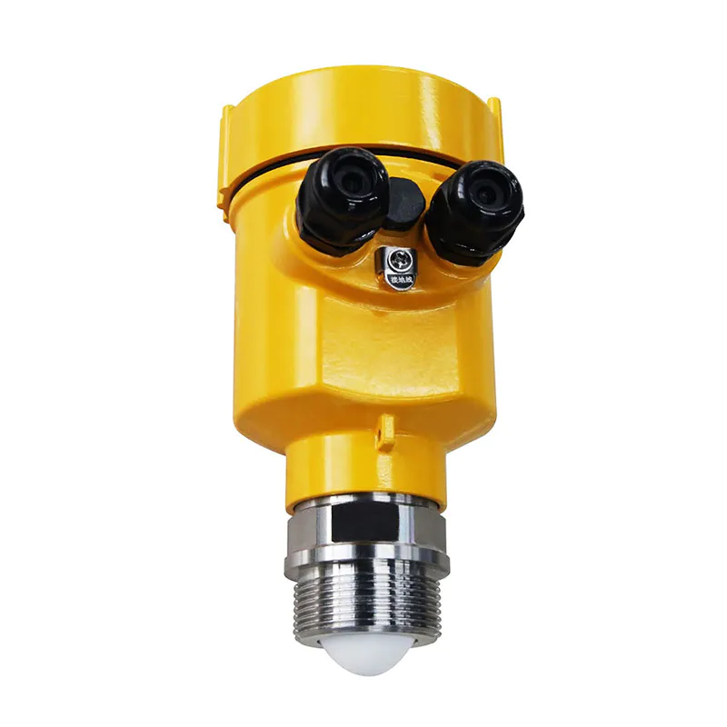
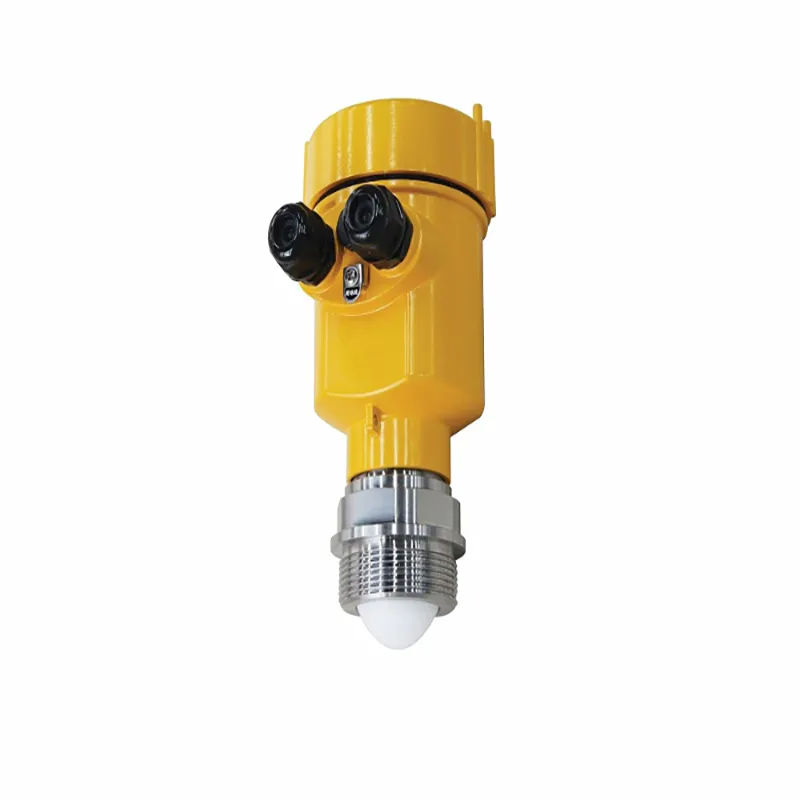
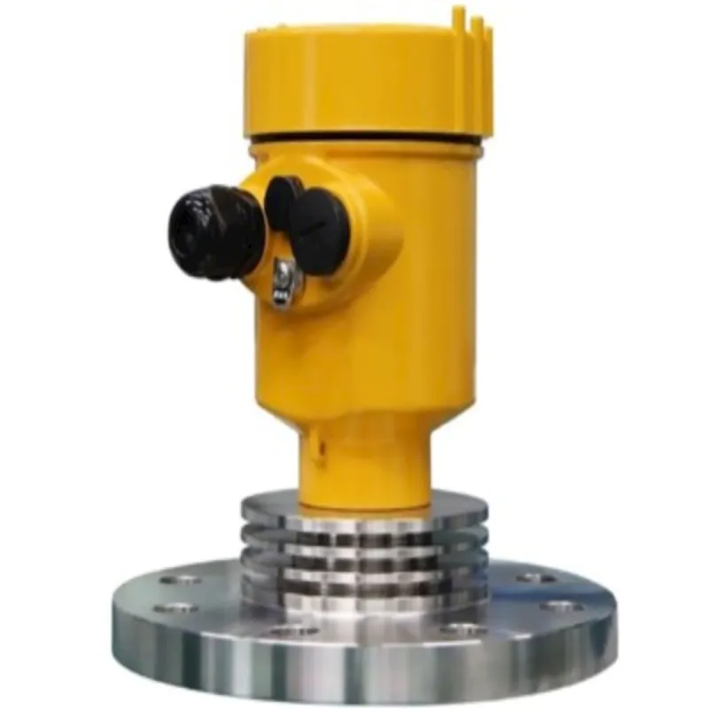
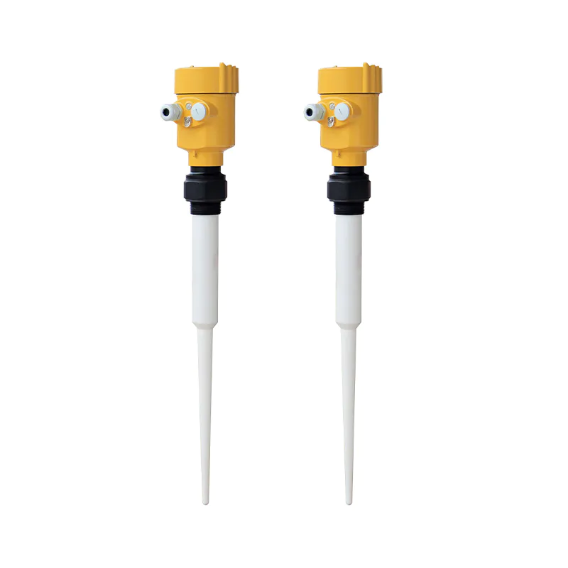
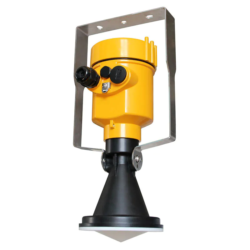
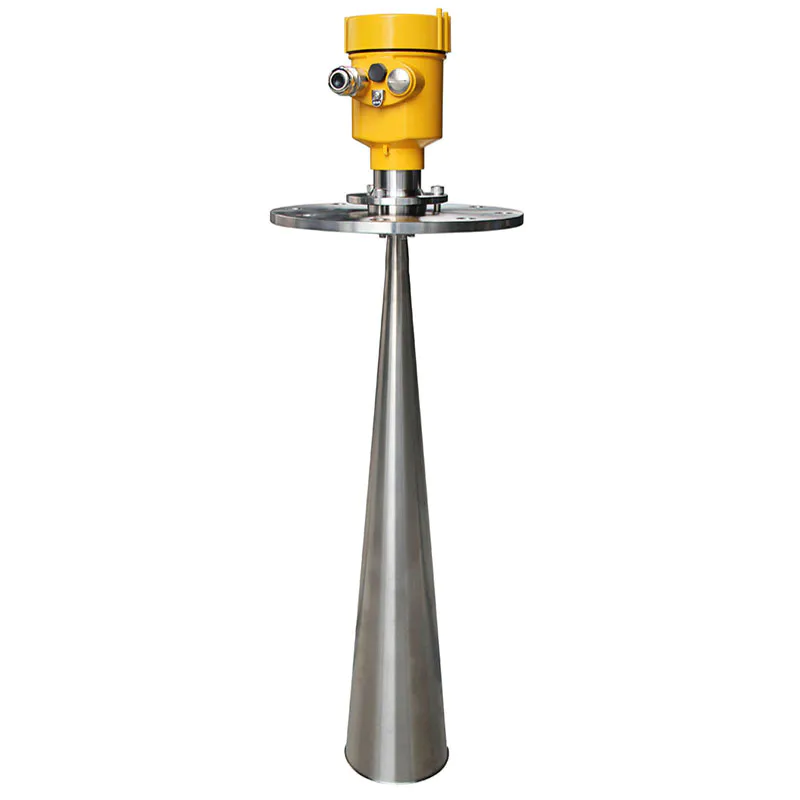
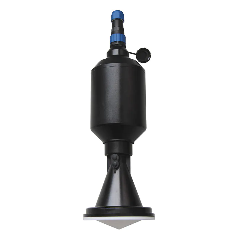
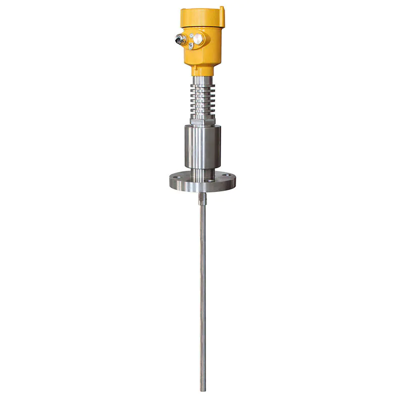
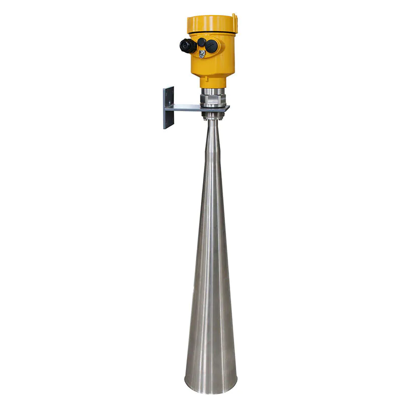
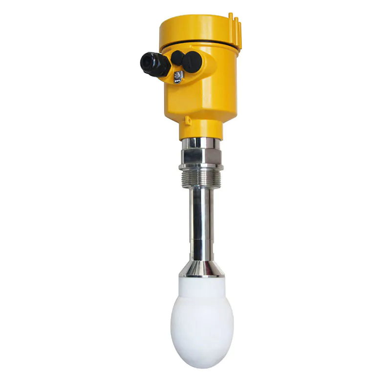
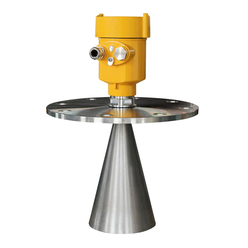
Radar Level Meter 80G FM Radar Type Level Measuring Instrument Kaidi KD-FMW21S FM
KDRD-FMW Series Sensor Is 80G FM Radar Type Level Measuring Instrument, Measuring Distance Up To 150 Meters
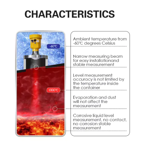
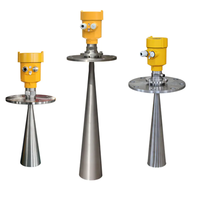
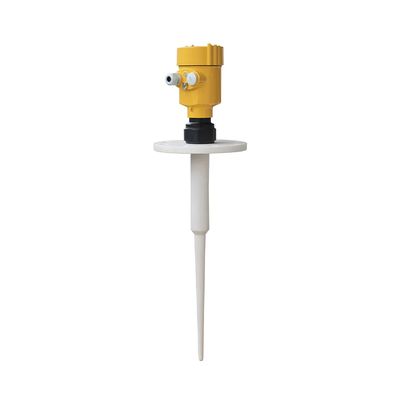
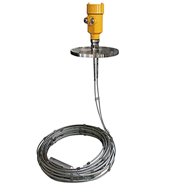
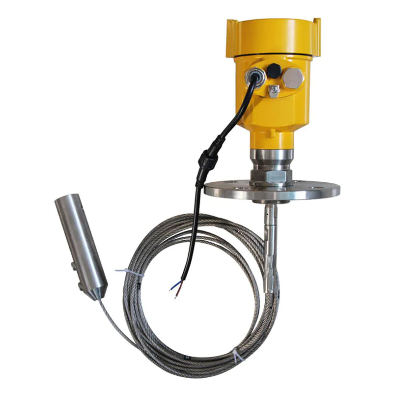
6GHz intelligent series radar level meter is suitable for non-contact continuous measurement of level of liquid, slurry, granule and lump material, suitable for temperature and pressure changes; occasions where inert gas and volatilization exist.
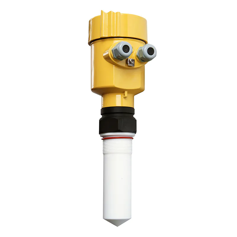
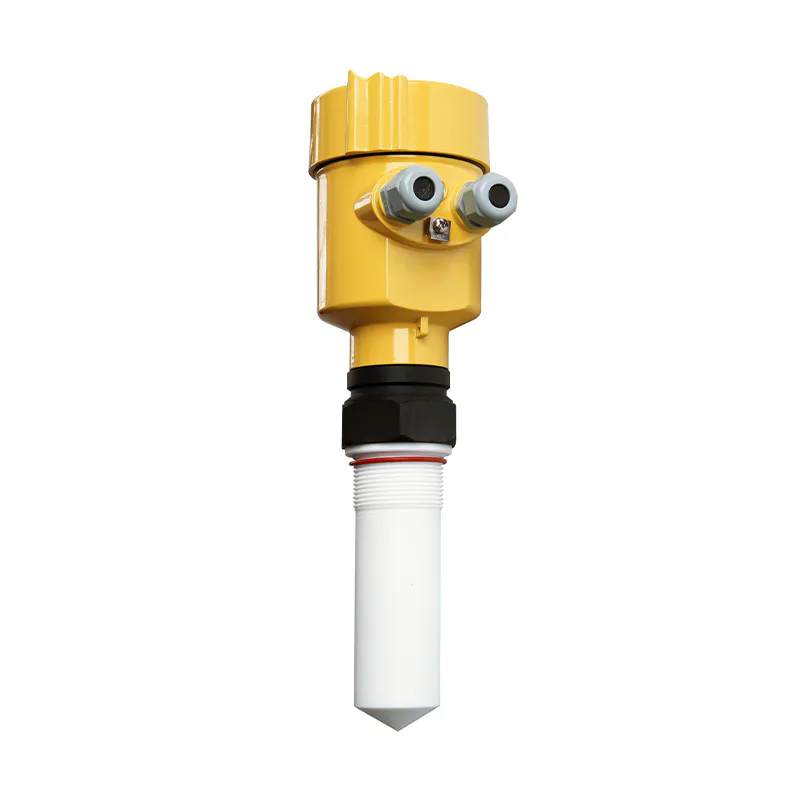
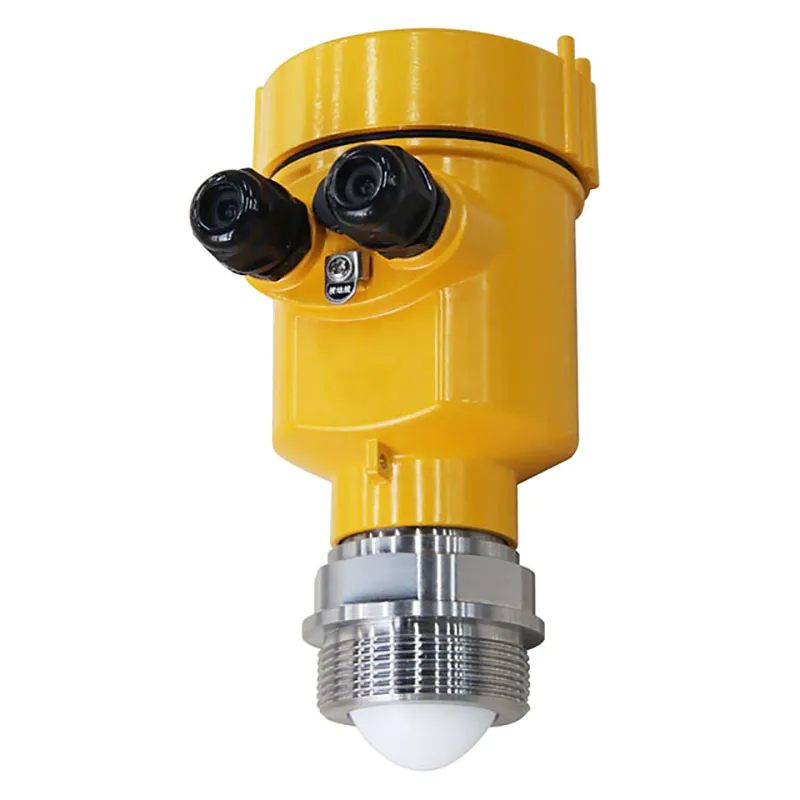
It adopts the measurement method of microwave pulse, and can work normally in the industrial frequency band range. Low beam energy, can be installed in a variety of metal, non-metallic containers or pipes, no harm to human body and the environment
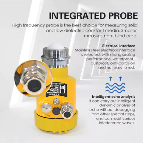
Very short microwave pulses with very low energy are transmitted and received through the antenna system. The radar wave travels at the speed of light. The running time can be converted into a level signal by means of electronic components. A special time-stretching method ensures stable and accurate measurements in a very short time. Even in the case of complex conditions and spurious echoes, the level echoes can be accurately analyzed using microprocessor technology and commissioning software.
The antenna receives the reflected microwave pulses and transmits them to the electronics. The microprocessor processes this signal and identifies the echoes generated by the micropulses on the material surface. The correct identification of the echo signal is done by the pulse software with an accuracy of millimeters.
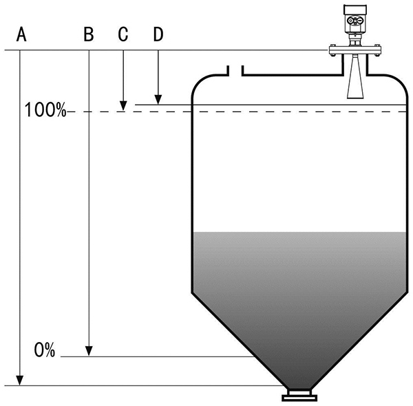
The distance D from the material surface is proportional to the time travel T of the pulse: D=C×T/2; where C is the speed of light. Since the distance E from the empty tank is known, the level L is: L = E - D.
It is set by entering the empty tank height E (=zero), full tank height F (=full range) and some application parameters, which will automatically adapt the instrument to the measurement environment. Corresponding to 4-20mA output
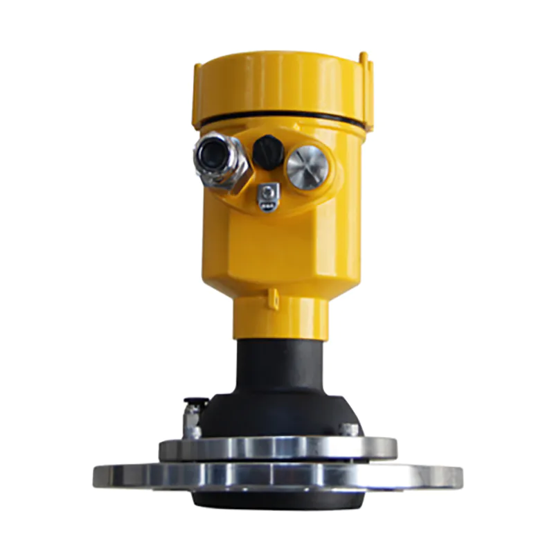
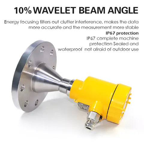
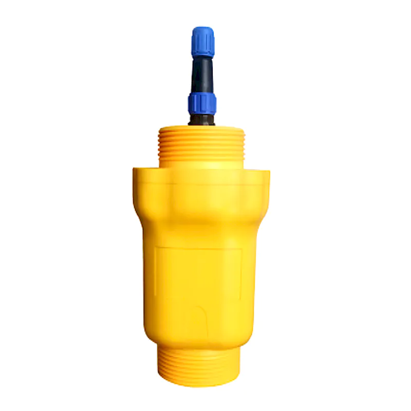
This instrument fully meets the requirements of protection class IP66/67. Please make sure that the cable sealing head is waterproof. As shown
How to ensure that the installation meets the requirements of IP67.
Please make sure that the sealing head is not damaged.
Please make sure that the cable is not damaged.
Please ensure that the cable used meets the requirements of the electrical connection specification.
Before entering the electrical connection, bend the cable downwards to ensure that water does not flow into the housing, see ①
Please tighten the cable sealing head, see ②
Please plug the unused electrical connections with blind plugs, see ③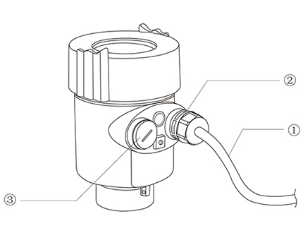
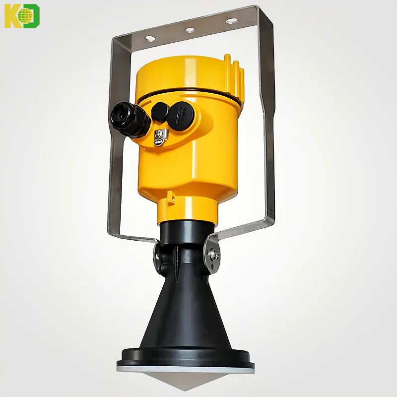
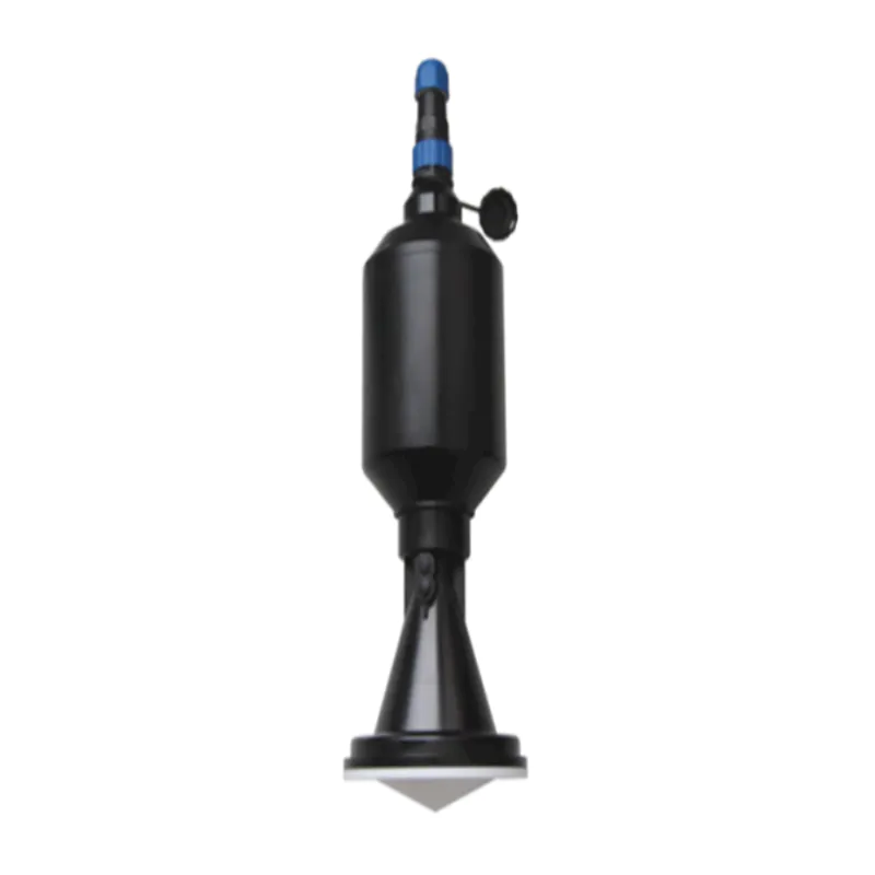
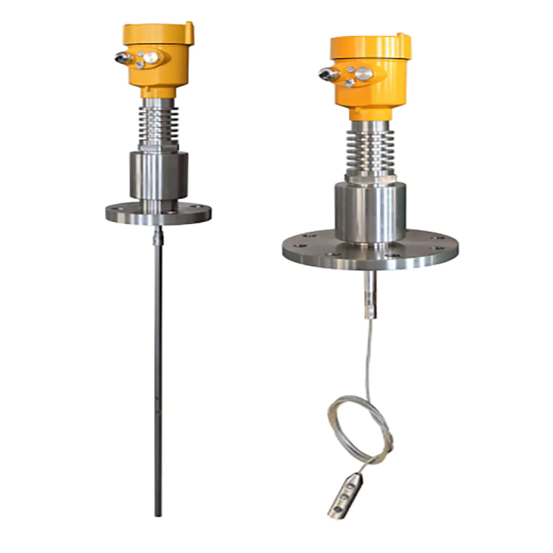
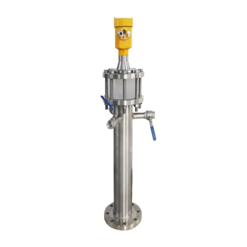
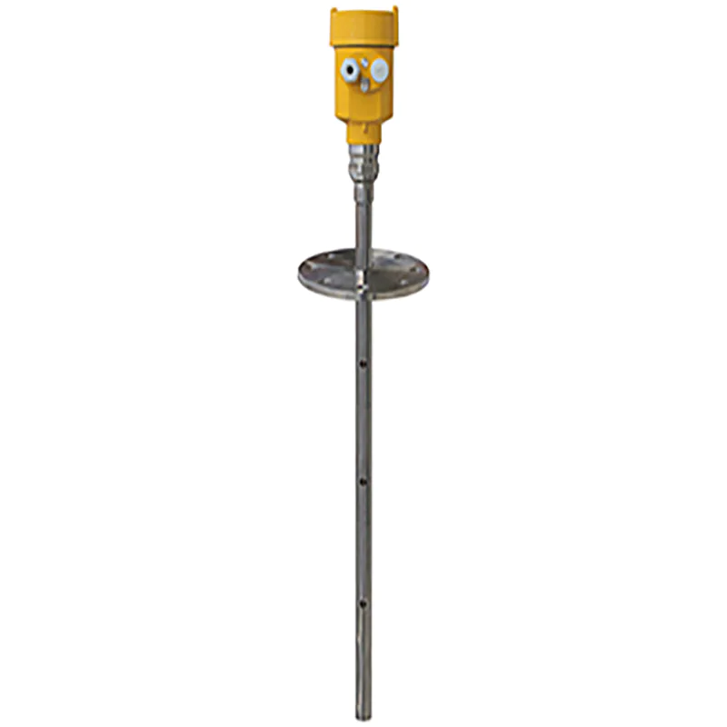
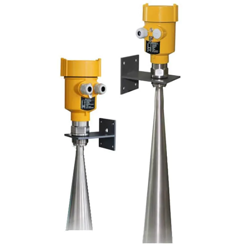
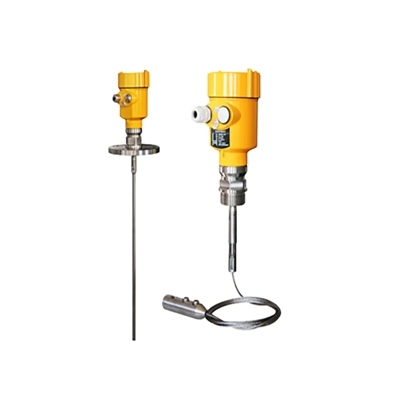
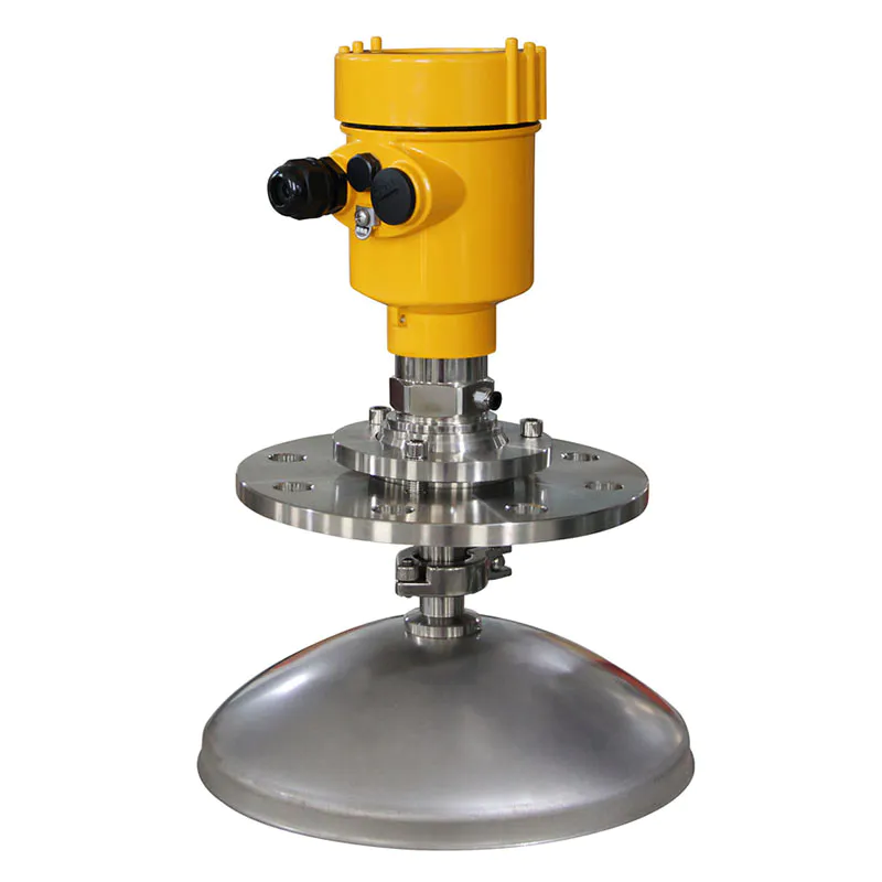
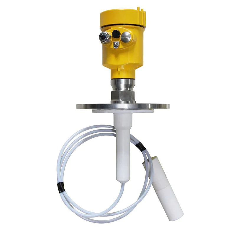
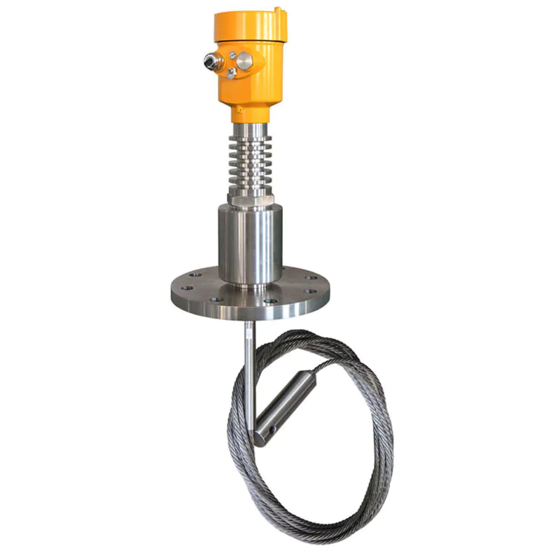
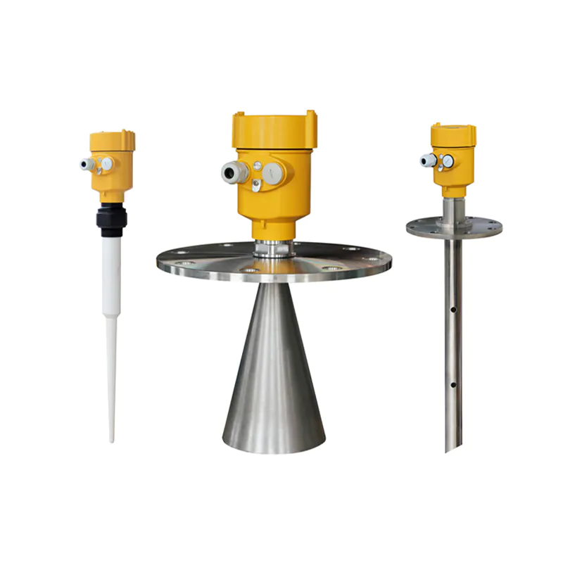
Applicable media: solid particles or lumps, not for solid powders
Applications: lime lump measurement; raw coal lump measurement
Explosion-proof certification: Exia IIC T6 Ga/ Exd IIC T6 Gb
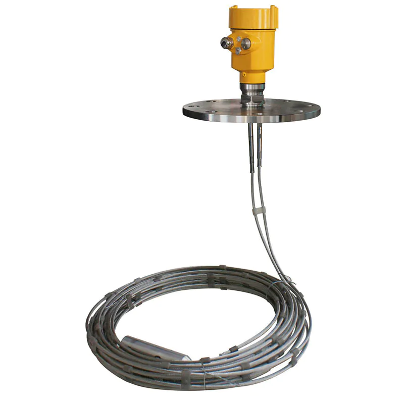
Measuring range: 35m
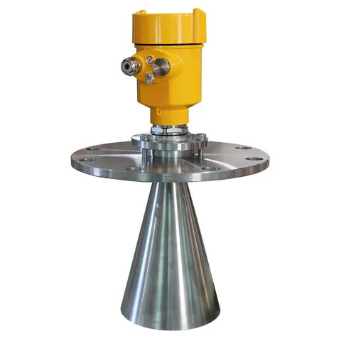
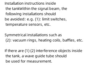
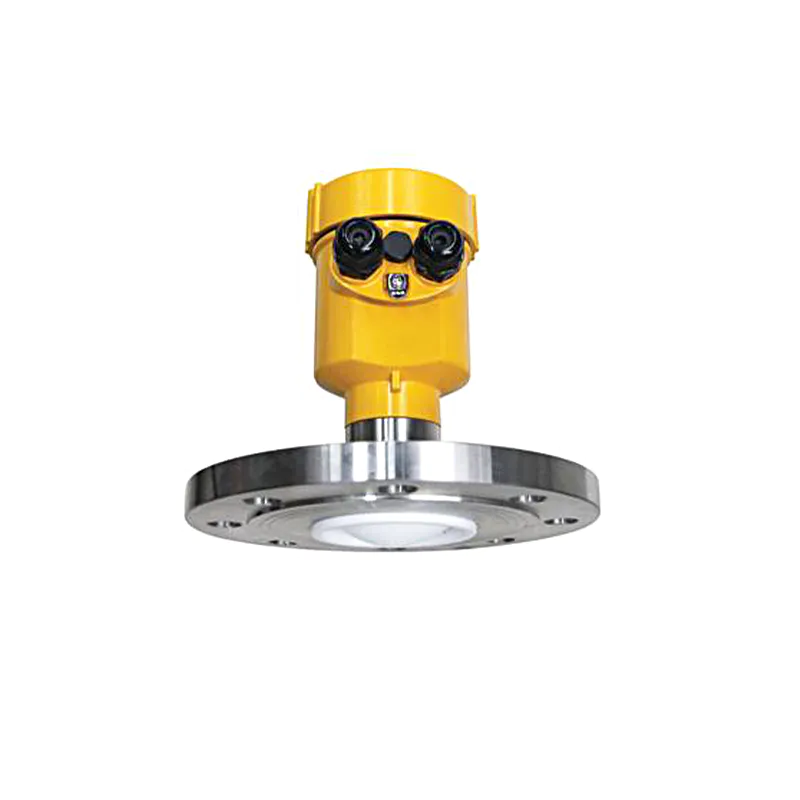
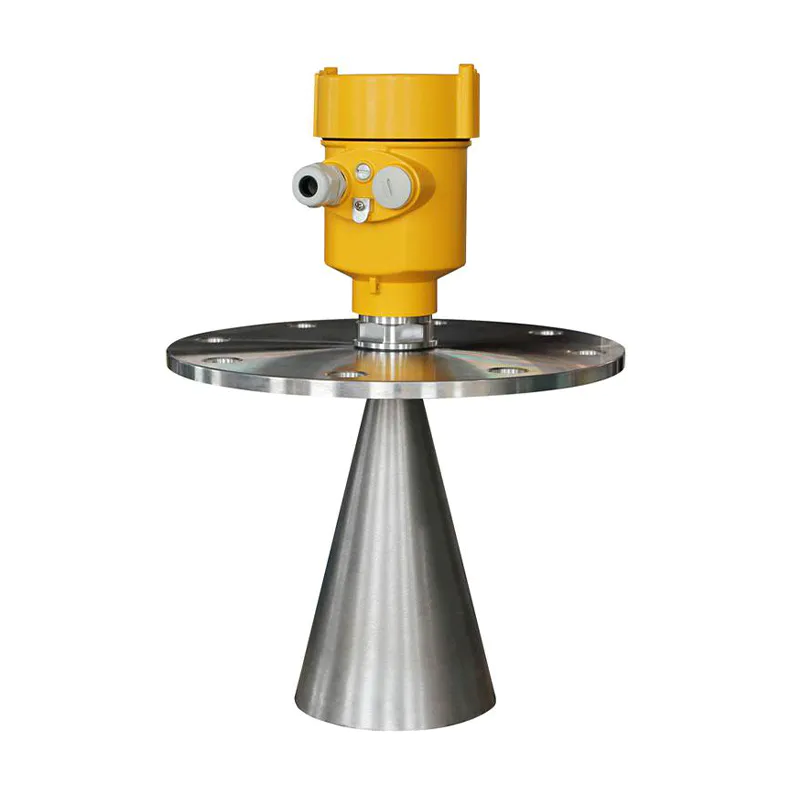
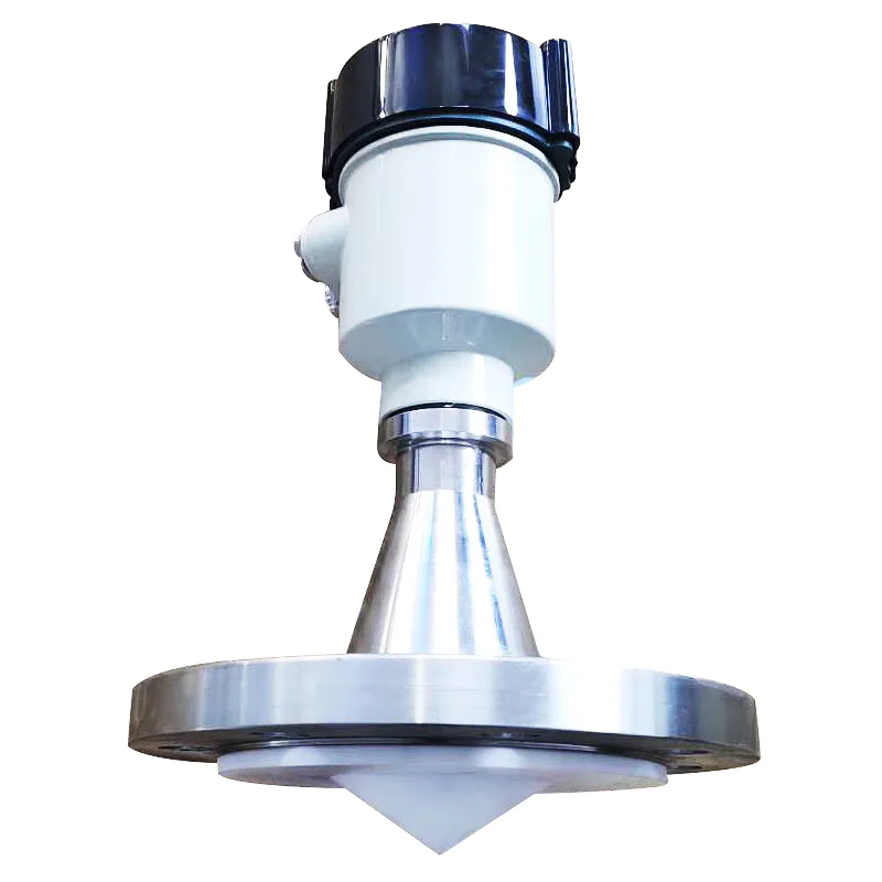
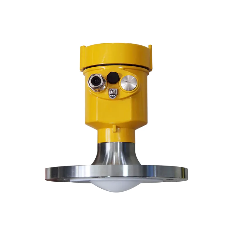
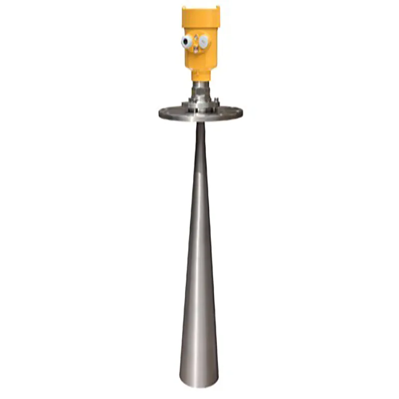
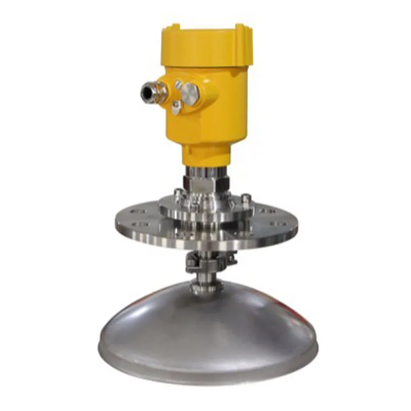
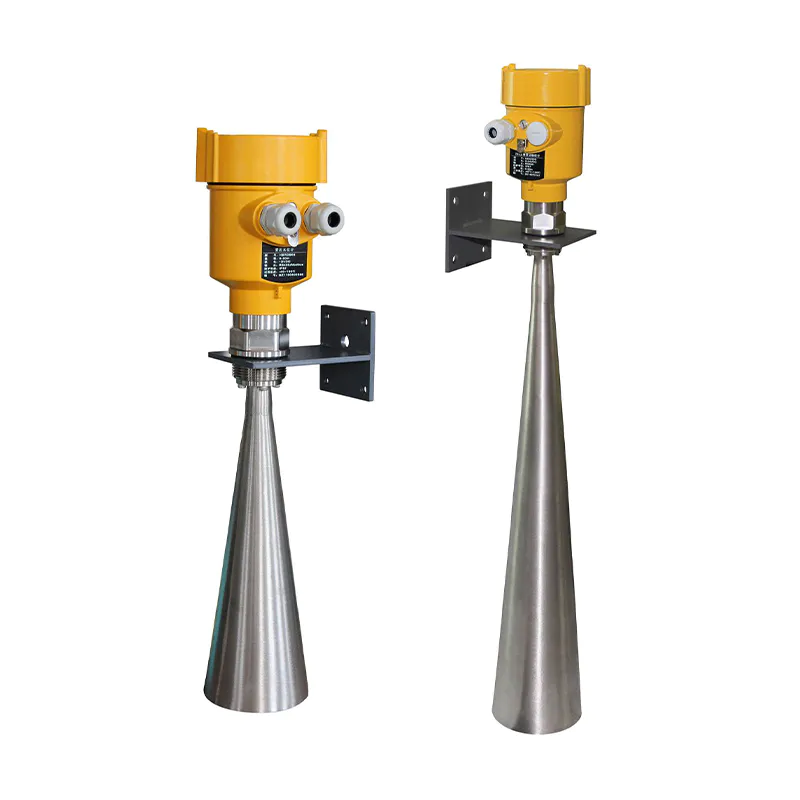
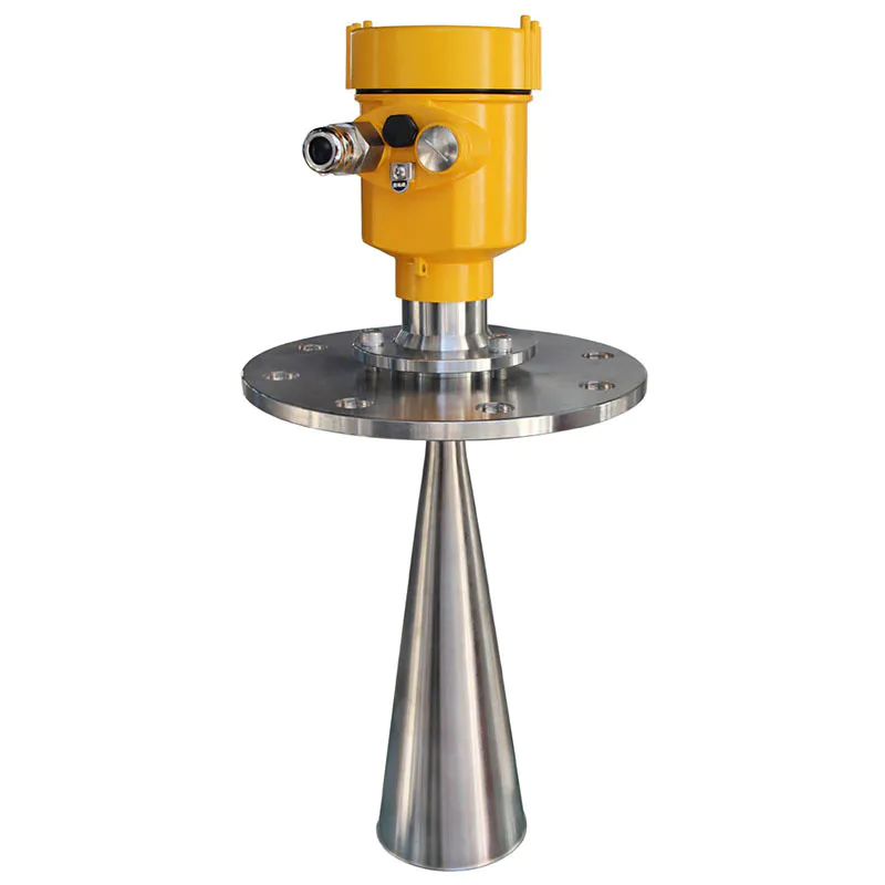
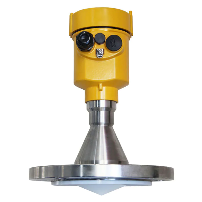
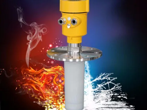
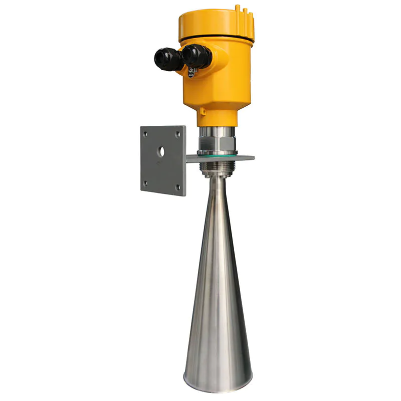
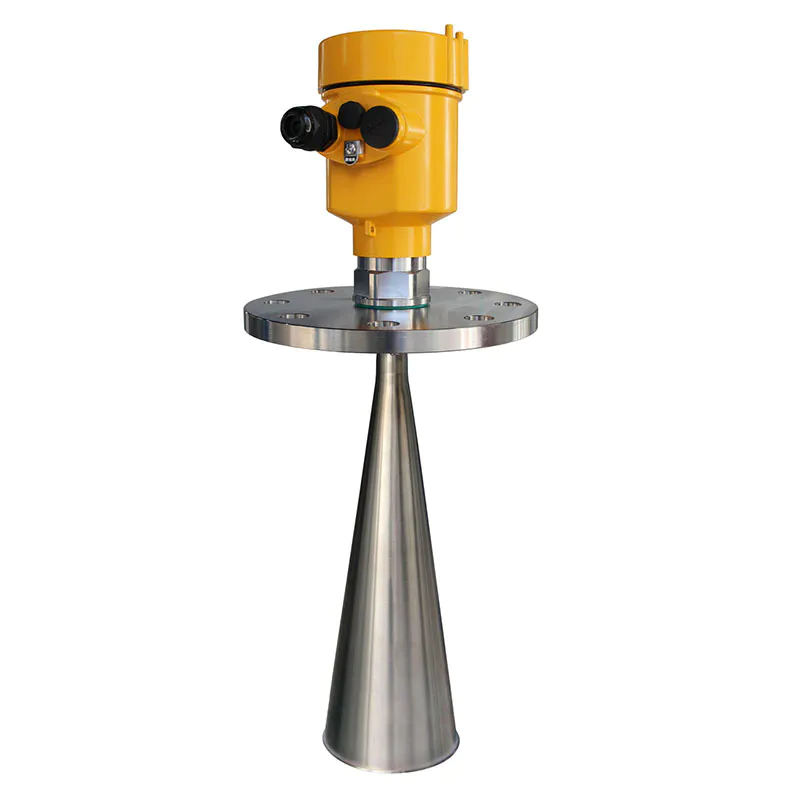
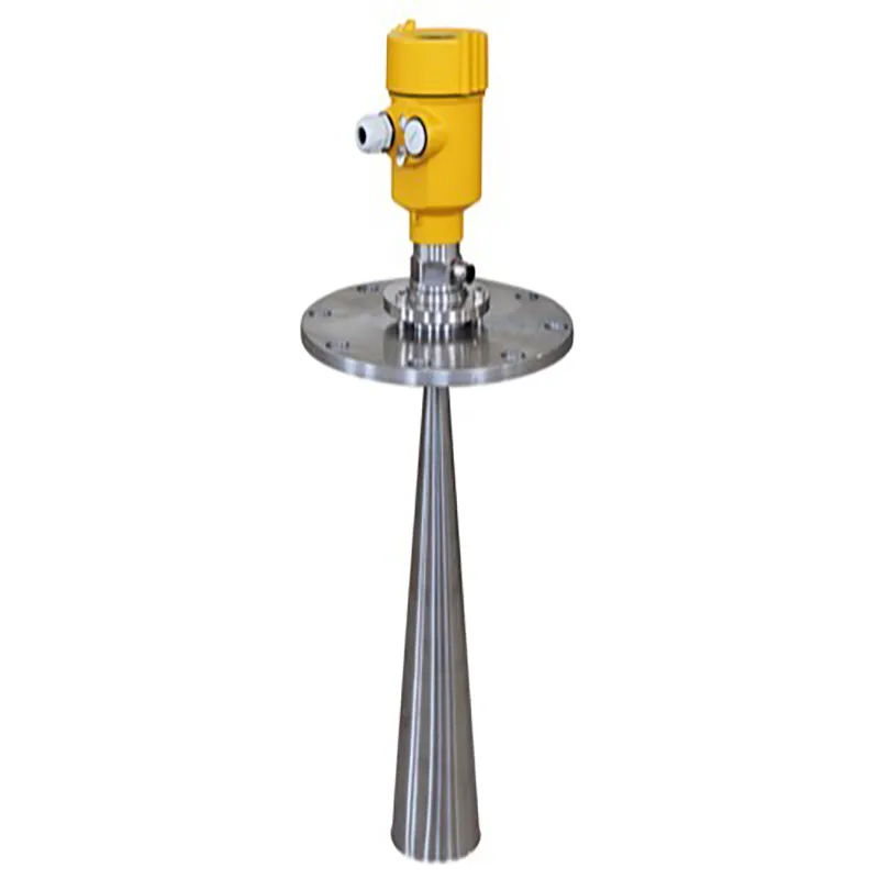
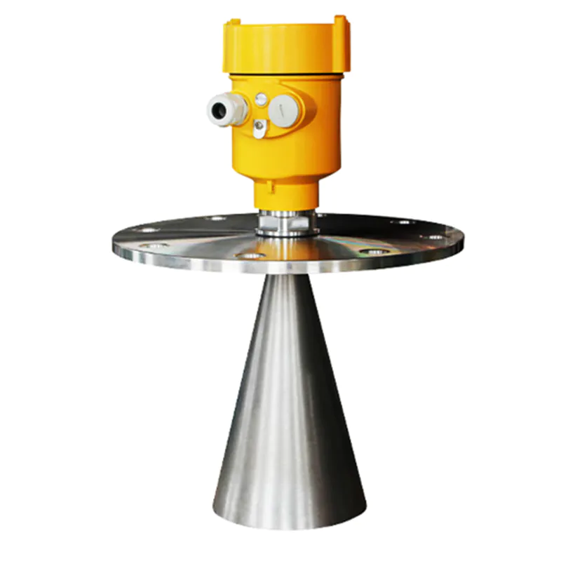
Antenna: Horn antenna
Frequency: 6 GHz
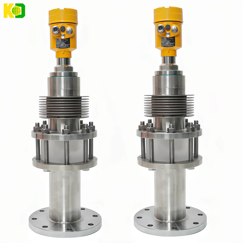
Process temperature: -40 to 130°C (standard type) / -40 to 250°C (high temperature type)
Measurement accuracy: ±20mm
Process pressure: (-0.1~0.3)MPa
Signal output: (4~20)mA/HART
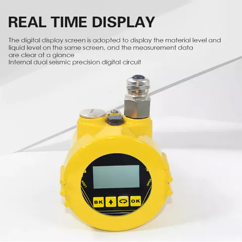
Field display: four-digit LCD programmable
Power supply: two-wire (DC24V) four-wire (DC24V/AC220V)
Repeatability: ± 1mm
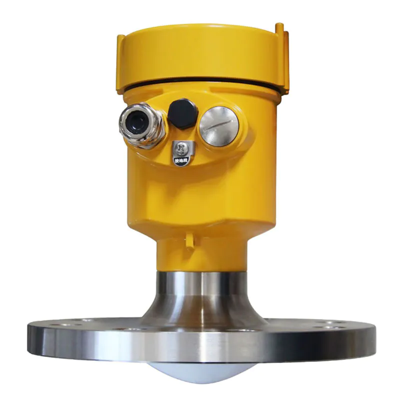
Housing: Single chamber/aluminum Double chamber/plastic/stainless steel Single chamber
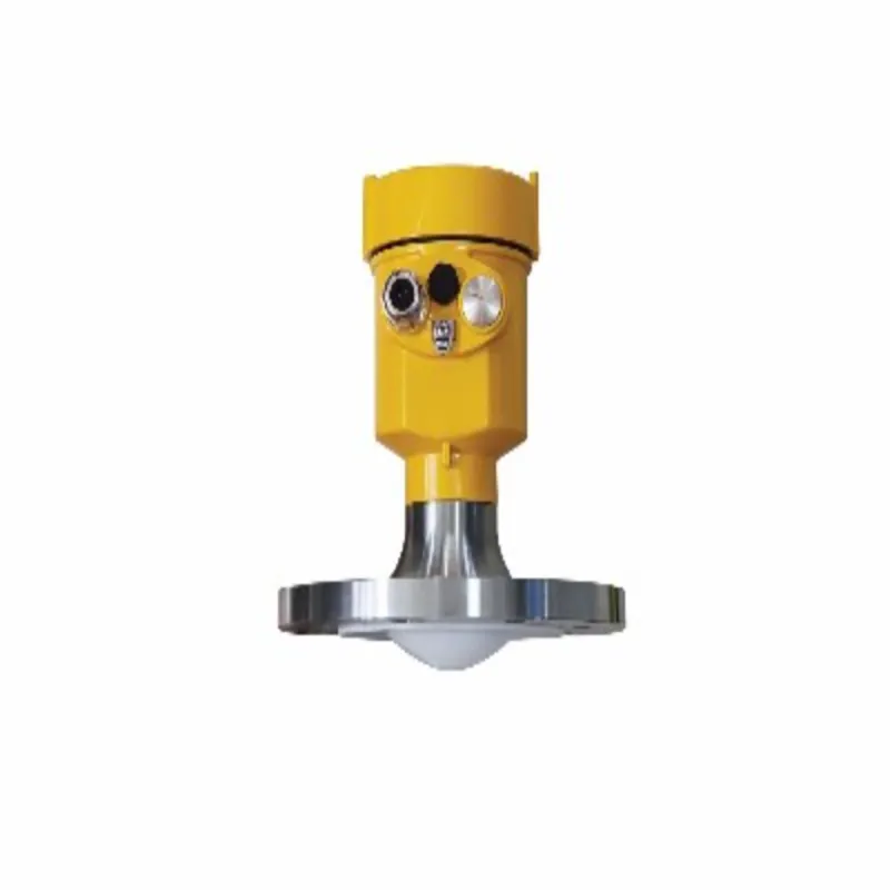
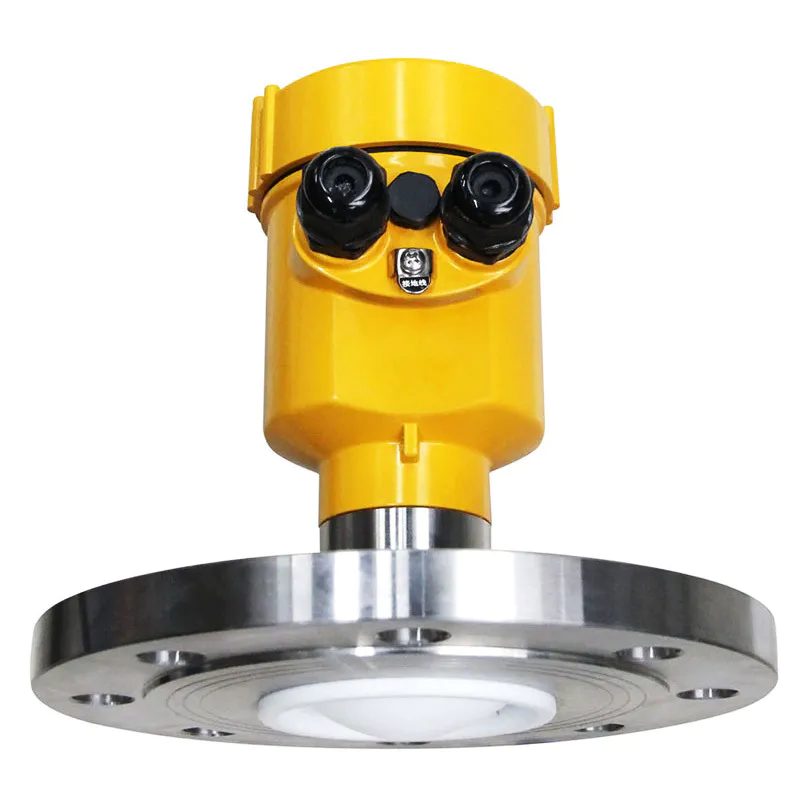
Process connection: Universal joint flange (optional)
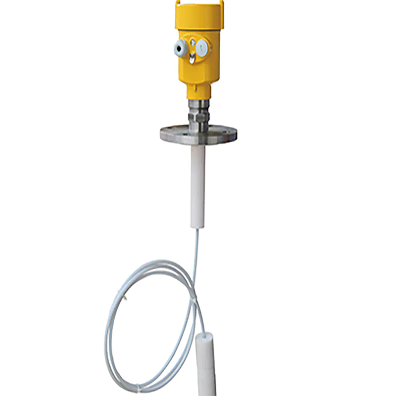
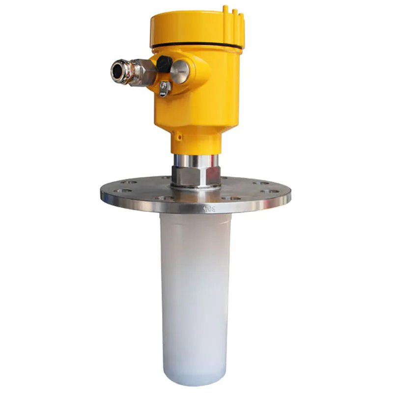
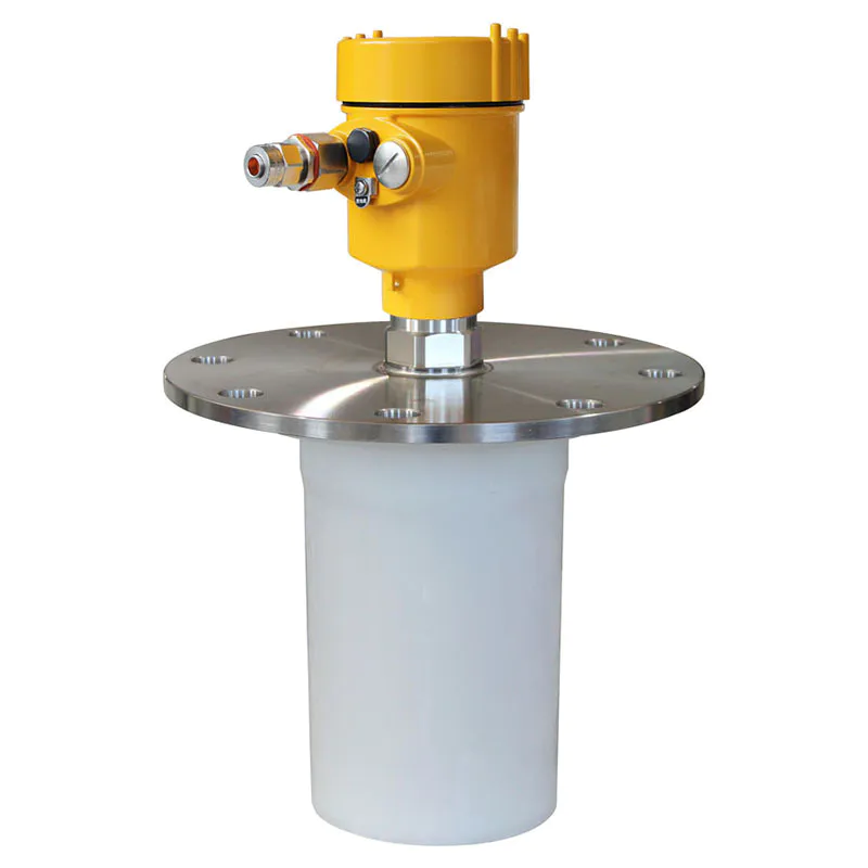
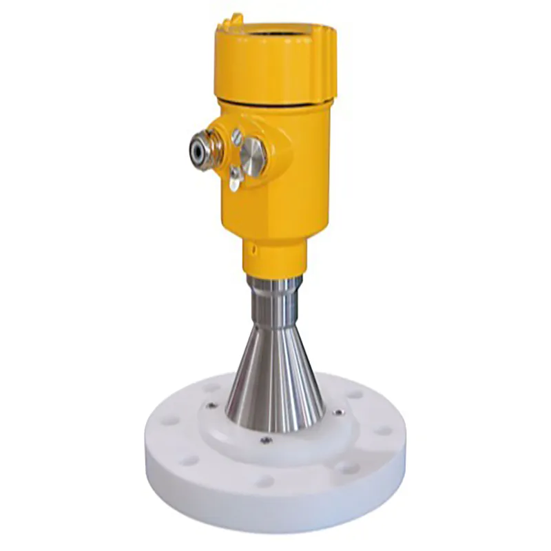
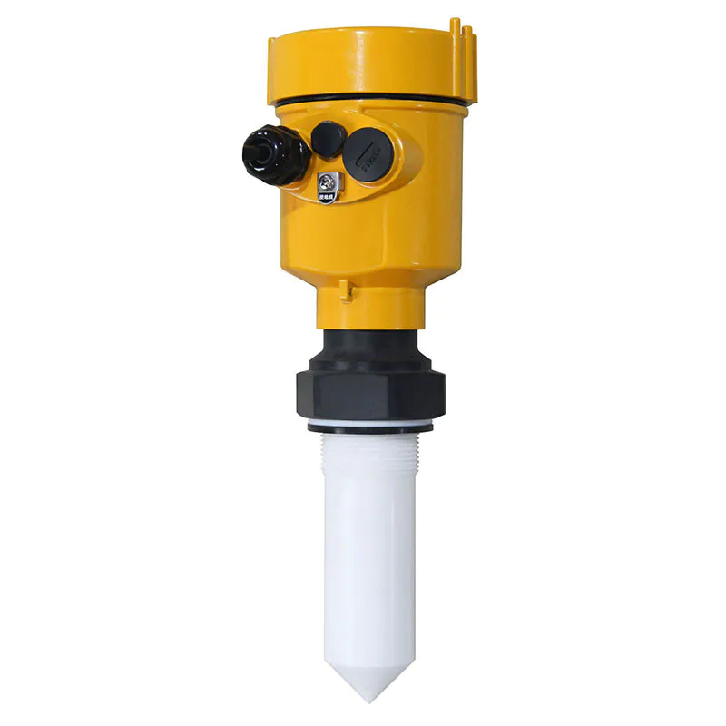
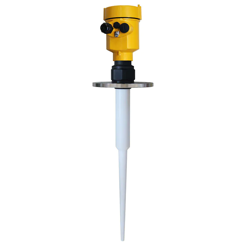
General data Material Antenna PTFE, PP
Housing Aluminum, plastic, antistatic PP, stainless steel 316
Seal between housing and enclosure Silicone rubber
Housing sight glass Polycarbonate
Grounding terminal Stainless steel
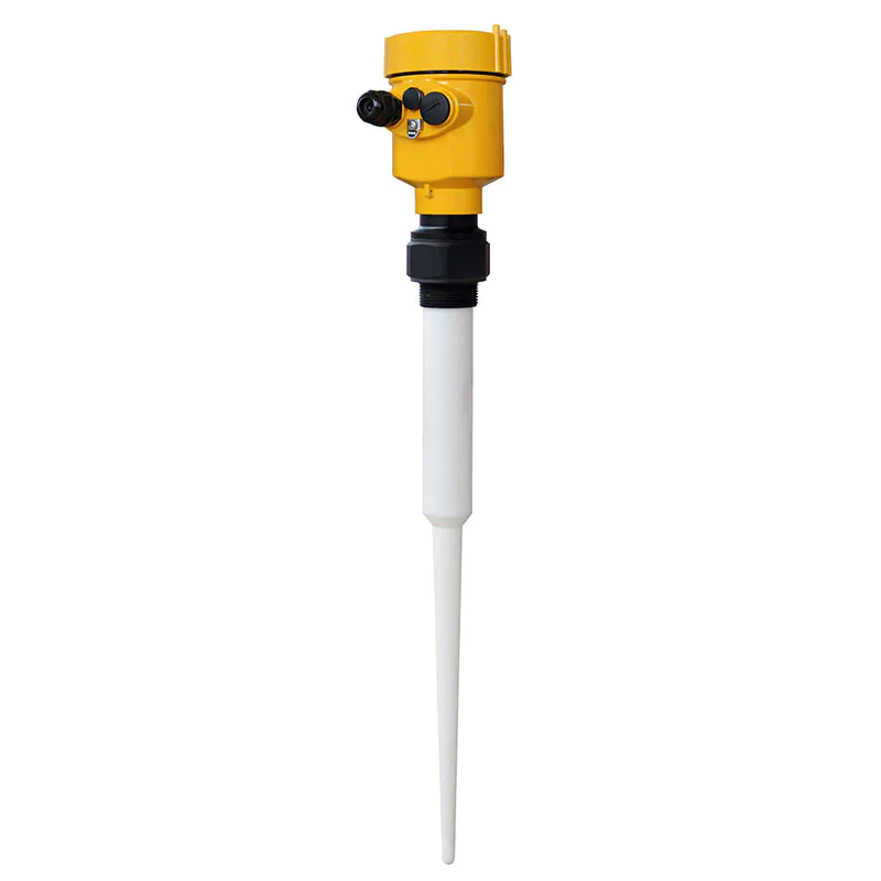
Process connection HBRD801 G1½″A thread or 1½″NPT thread / flange
KD802 PTFE Flanged Flange
KD803 Stainless Steel Flange
KD804 Stainless Steel Flange
KD805 Stainless Steel Flange
KD806 Stainless Steel Flange
Power supply voltage Two-wire system Standard type (16~26)V DC
Intrinsically safe (21.6~26.4)V DC
Power consumption max. 22.5mA
Allowable ripple
- <100Hz Uss < lV
- (100~100K)Hz Uss < l0mV
Flameproof type (22. 8 to 26. 4) V DC Two-wire system
(198~242) V AC 4-wire / 110V AC 4-wire
Power consumption max. 1VA, 1W
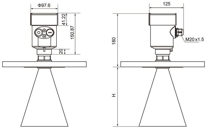
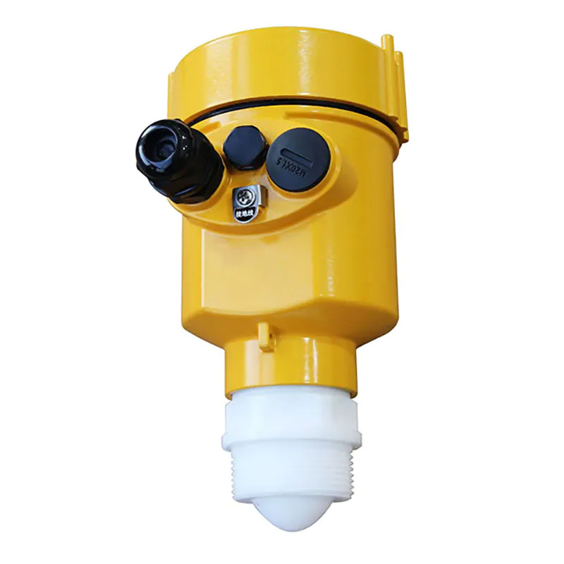
Cable parameters Cable inlet/plug 1 M20xl.5 cable inlet (cable diameter 5 to 9 mm)
1 blind plug M20xl.5
Spring terminal block for wire cross section 2.5 mm²
Output parameters Output signal (4 to 20)mA/HART
Resolution 1.6μA
Fault signal Current output constant; 20.5mA; 22mA; 3.9mA
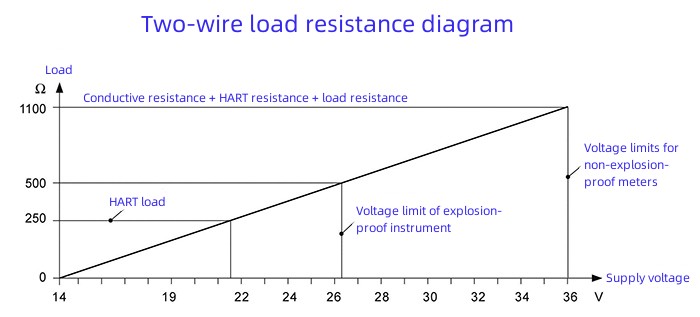
Two-wire load resistance See figure below
Four-wire load resistance 500Ω max.
Integration time (0 to 36)s, adjustable
Characteristic parameters Blind area End of antenna
KD801 20m (liquid)
KD802 20m (liquid)
KD803 35m
KD804 35m
KD805 20m
KD806 15m
Measurement interval approx. 1s (depending on parameter setting)
Adjustment time approx. 1s (depending on parameter setting)
Resolution 1mm
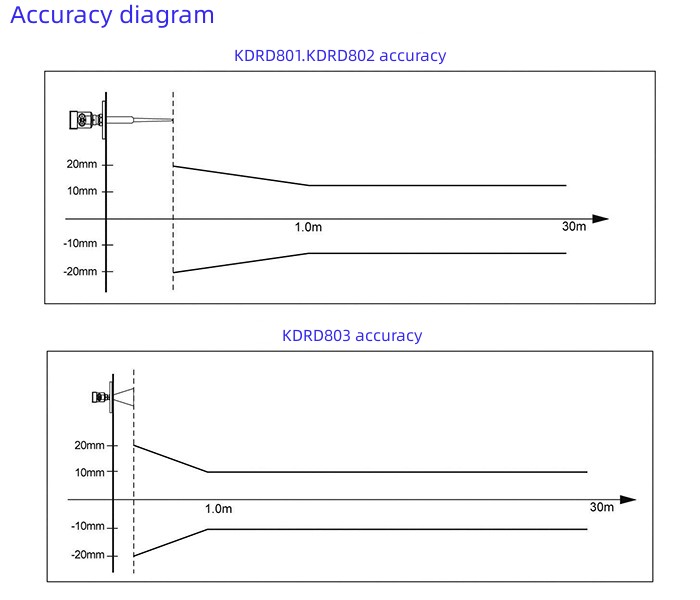
Accuracy 10mm or <0.1% (see accuracy diagram below)
Operating storage and transport temperature (-40 to 80) °C
Process temperature (temperature of antenna section)
KD801 -40~130℃
KD802 -40~130℃ (standard type) / -40~180℃ (high temperature type)
KD803 -40~130℃ (Standard type) / -40~180℃ (High temperature type)
KD804 -40~130℃ (standard type) / -40~180℃ (high temperature type)
KD805 -40~130℃ (standard type) / -40~180℃ (high temperature type)
KD806 (-40~400)℃
Relative humidity <95%
Pressure inside the tank Max. 4MPa
Shock resistance Mechanical vibration l0m/s² , (10~150)Hz
INSTRUMENT LINEARITY
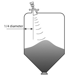
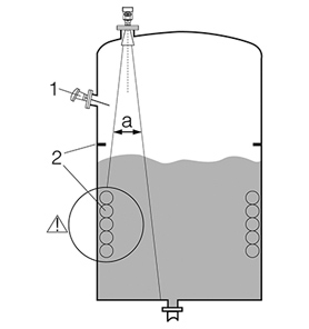
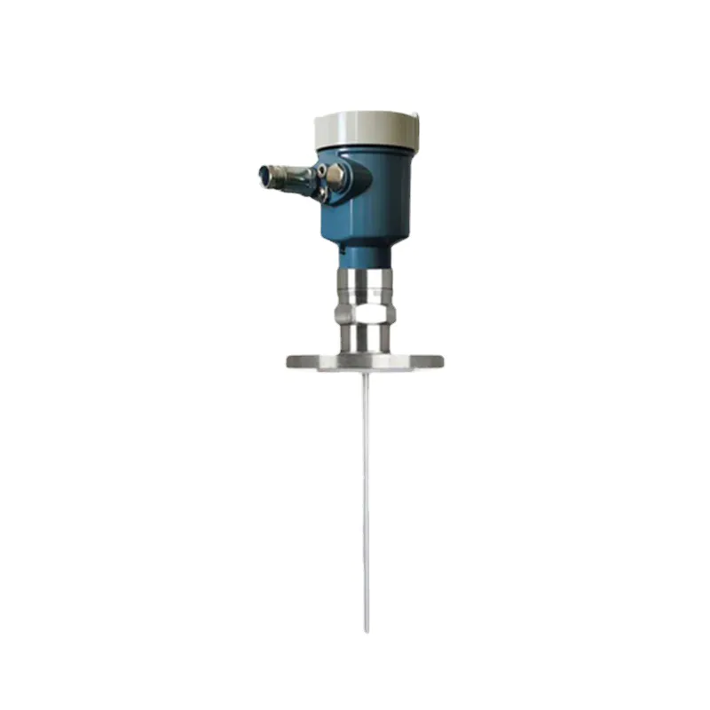
Recommended location (2), the tank wall to the outer wall of the installation short pipe should meet the following requirements: the best distance from the tank wall is 1/4 or 1/6 of the tank diameter, the minimum installation distance from the tank wall is 1/10 of the measurement range. for example: 10m level tank, the minimum installation distance from the tank wall should be 1m.
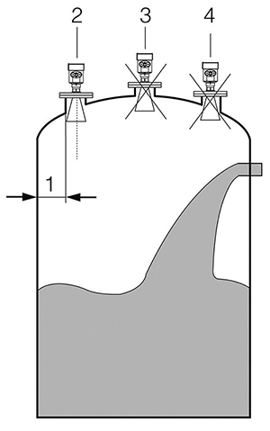
● Cannot be installed above the inlet (4)
● It cannot be installed in the center (3). If it is installed in the center, multiple false echoes will be generated and the interference echoes will cause the real signal to be lost.
● If the distance between the instrument and the tank wall cannot be maintained, the medium on the tank wall will adhere to cause false echoes, and false echoes should be stored during the commissioning of the instrument.
We are here to help you! If you close the chatbox, you will automatically receive a response from us via email. Please be sure to leave your contact details so that we can better assist


![kaidi KD-906 26G Radar Level Meter [Anti-corrosion] High Temperature Intelligent](https://img80003270.weyesimg.com/uploads/kaidi86.com/images/16760218661446.jpg?imageView2/2/w/1920/q/80/format/webp)


![kaidi KD-802 6G Radar Level Meter [Anti-corrosion Type]](https://img80003270.weyesimg.com/uploads/kaidi86.com/images/15936739299092.jpg?imageView2/2/w/1920/q/80/format/webp)
![kaidi KD-FMF15 FM radar level meter [chemical and electric power industry]](https://img80003270.weyesimg.com/uploads/kaidi86.com/images/15936722293812.jpg?imageView2/2/w/1920/q/80/format/webp)