BETTER TOUCH BETTER BUSINESS
Contact Sales at KAIDI.
Radar level gauges enable non-contact level measurement under any process conditions. The gauge transmits microwave signals from above into the medium, which are then reflected back from the surface. Based on the received signals, the gauge determines the distance to the medium and calculates an accurate level measurement.
Whether your measurement requirements involve liquids, solids, high or low temperatures, or corrosive substances, radar level gauges can fulfil all your application needs.
During practical operation of radar level gauges, users often encounter terminology in the operating manual that proves confusing. This article will guide you through frequently encountered technical terms to enhance your familiarity.
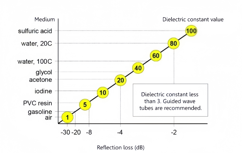
I. Dielectric Constant
The dielectric constant, relative permittivity, is a dimensionless quantity denoted by the Greek letter ε. It represents the ratio of capacitance in a capacitor using a given material as dielectric to that in a vacuum, serving as a measure of a substance's capacity to retain electric charge.
In radar level gauges, the dielectric constant is crucial for determining the type and properties of the measured material. Different materials exhibit varying dielectric constants due to differences in molecular structure and composition. Generally, materials with higher dielectric constants respond more strongly to electric fields, while those with lower constants respond more weakly.
II. Operating Frequency
The operating frequency of a radar level gauge refers to the frequency range at which it transmits radar waves. Radar level gauges can be categorised as high-frequency or low-frequency based on their transmission frequency. Low-frequency radar operates within the 100MHz to 8GHz range, while units transmitting above 8GHz up to 120GHz are classified as high-frequency radar level gauges.
In practical engineering applications, low-frequency radar level gauges are primarily employed for measuring liquid media and in environments requiring small measurement ranges. High-frequency radar, owing to advantages such as higher energy output, achieves greater measurement ranges and is applicable to a wider variety of operating conditions. The radar waves emitted by high-frequency radar level gauges demonstrate superior measurement performance compared to low-frequency radar when dealing with irregular surfaces such as solid materials, powders, and granular substances.
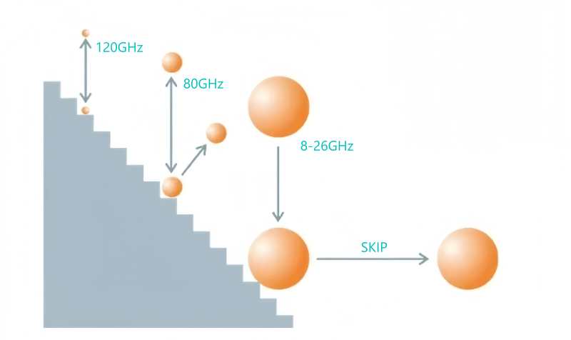
The operating frequency significantly impacts the performance and application of radar level gauges, as demonstrated below:
Penetration capability: The higher the operating frequency, the poorer the radar wave's penetration capability. However, high-frequency radar waves suffer greater attenuation when passing through liquids or solid materials. Consequently, in certain circumstances, low-frequency radar level transmitters may prove more suitable for measuring denser materials.
Measurement Accuracy: High-frequency radar waves possess shorter wavelengths, thereby offering greater measurement precision. In contrast, low-frequency radar waves may be more susceptible to interference, potentially compromising measurement accuracy.
III. Blind Zone
The blind zone of a radar level gauge refers to the area where radar waves cannot be accurately measured, typically situated near the radar antenna. This phenomenon arises from the physical structure of the radar and the characteristics of signal propagation. Specifically, it manifests as an inability to accurately detect the target or measure the position of an object within a certain distance range; measurement accuracy can only be guaranteed once the object moves beyond this range.
The blind zone may arise from multiple factors including geographical conditions, electromagnetic wave propagation characteristics, target velocity, and the radar unit itself. This zone significantly impacts the measurement accuracy of radar level gauges, making the selection of products with a smaller blind zone crucial during specification.
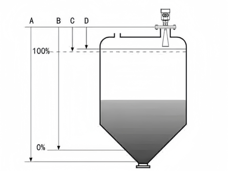
A. Range setting; B. Low-end adjustment (4mA reference point); C. High-end adjustment (20mA reference point); D. Deadband
The primary reasons for the existence of blind spots include:
Near-field effect: Within the near-field region adjacent to a radar antenna, signal propagation characteristics differ from those in the far-field region. This may result in signal attenuation or ambiguous reflections, thereby creating blind spots.
Antenna design: The design and configuration of a radar antenna influence the formation of blind spots. For instance, certain antenna structures may exhibit a wider radiation beam in specific directions, leading to larger blind spots in those directions.
Beam Angle: The beam angle of radar waves also influences blind zone size. A narrower beam angle typically creates larger blind zones, as radar waves become more susceptible to obstruction or interference, preventing them from reaching target areas.
Environmental Interference: The installation and operational environment further affects the blind zones of radar level transmitters. For instance, metallic structures or other obstacles may cause reflections or attenuation along the radar wave propagation path, resulting in blind zones within these areas.
IV. Echo
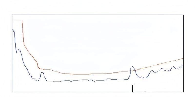
The operating principle of radar level gauges is based on echo ranging. The signal emitted by the radar level gauge is reflected back from the material surface, forming a received signal. The time difference between the transmitted and received waves is directly proportional to the distance between the material surface and the antenna. By measuring the propagation time, the position and height of the material can be determined.
V. Beam Angle
The beam angle is a key parameter for assessing the directionality and scanning range of a radar beam. The beam angle of a radar level gauge, also known as the antenna beam width, denotes the primary radiation angle range of the electromagnetic beam emitted by the radar antenna. It determines the spatial coverage and directionality of the radar system.
When the beam angle is small, the radar's directionality is more precise, with a relatively narrow range of reception or transmission; conversely, when the beam angle is large, the radar's directionality becomes more dispersed, with a broader range of reception or transmission.
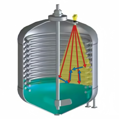
A larger beam angle is more likely to encounter obstacles, resulting in false echoes.
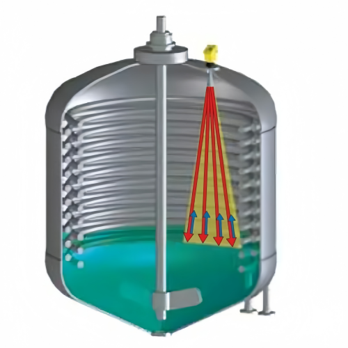
A narrower beam angle implies less interference.
VI. Range
The range of a radar level gauge refers to the maximum and minimum distance within which it can perform effective measurements.
Long Range: Refers to the maximum distance that a radar level gauge can measure. Typically, long range depends on factors such as the radar wave's power, frequency, antenna design, and environmental conditions. Radar level gauges with higher power and frequency can generally cover greater distances.
Short Range: Refers to the minimum distance that a radar level gauge can measure. Within the gauge's operational range, there is typically a short-range blind zone where the radar system cannot accurately determine the distance or height of objects. The short range is influenced by factors such as the antenna design, beam angle, and signal processing capabilities of the radar level gauge.
The determination of long and short ranges is crucial for the application of radar level gauges. When selecting and deploying radar level gauges, it is necessary to establish appropriate long and short range parameters based on actual application requirements and scenario characteristics to ensure the radar system can effectively fulfil measurement and monitoring demands.
We are here to help you! If you close the chatbox, you will automatically receive a response from us via email. Please be sure to leave your contact details so that we can better assist