 Español
  pусский
  العربية
  Português
BETTER TOUCH BETTER BUSINESS
Contact Sales at KAIDI.
Both throttling orifice plates and restriction orifice plates are based on the orifice throttling principle, but they exhibit significant differences in functional positioning, working principles, application scenarios, structural design, and standards/specifications. A detailed comparison is as follows:
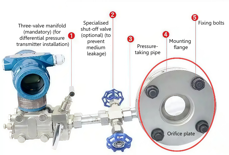
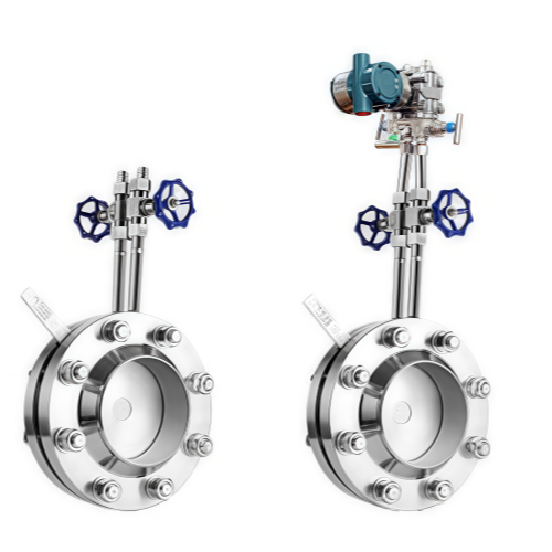
· Throttling Orifice Plate:Serves as the core component of a differential pressure flow measurement system and must be used in conjunction with differential pressure transmitters, pressure tapping devices, etc. Its core function is to precisely measure fluid flow rate through the pressure difference generated by the orifice, establishing a flow rate-pressure difference functional relationship based on Bernoulli's equation and the principle of flow continuity (e.g., per ISO 5167 standard). It is suitable for flow measurement of single-phase fluids (liquids, gases, steam) and is widely used in process monitoring, energy measurement, and experimental research in industries such as petroleum, chemical, and power.
· Restriction Orifice Plate: Functions as aflow/pressure control device, used torestrict fluid flow rate or reduce pressure, not for precise measurement. Typical applications include: pressure reduction of process fluids where high accuracy is not required, reducing erosion when large pressure drops exist across valves, ensuring continuous low flow (e.g., pump flush lines, hot standby pump bypasses, analysis sample lines), and reducing noise and wear in venting systems.
· Restriction Orifice Plate:
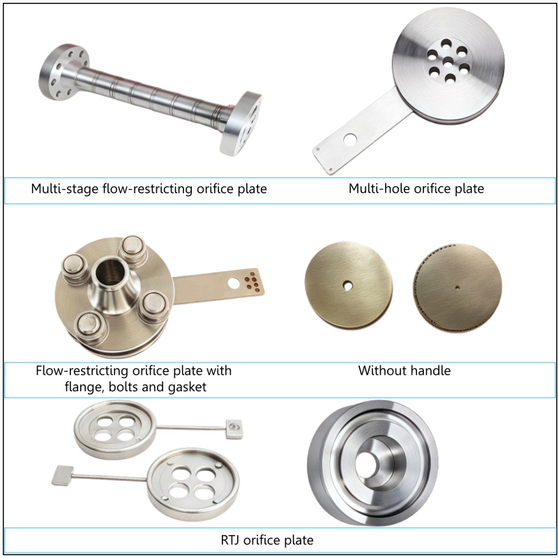
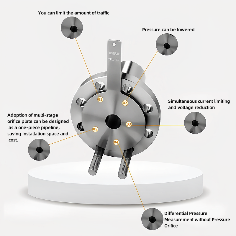
Directly restricts flow or reduces pressure through orifice resistance, without relying on a precise pressure difference-flow rate relationship. Design must avoid cavitation (pressure at the vena contracta should not fall below the saturated vapor pressure). For large pressure drop scenarios, multi-stage pressure reduction (pressure drop decreases geometrically per stage) or multi-hole designs are often used (e.g., single hole for DN≤150mm, multi-hole for DN>150mm), or optimization is achieved through orifice diameter and number of plates (common orifice diameters include 12.5mm, 20mm, 25mm, 40mm).
· Throttling Orifice Plate: Suitable for scenarios requiring precise flow measurement, such as process material flow monitoring, energy metering, and experimental research. Must comply with international/national standards (e.g., ISO5167, GB2624). The fluid must be single-phase, homogeneous, without phase change, and the flow stream must be parallel to the pipeline axis.
Restriction Orifice Plate: Focuses on flow restriction and pressure control, such as:
1. Plates in series across valves experiencing large pressure drops to reduce fluid erosion on the valve.
2. Pressure reduction and noise attenuation in venting systems.
3. Scenarios requiring continuous low flow, such as pump bypass lines (low flow protection), flush lines for hot standby pumps.
4. Situations where process material pressure needs reduction and accuracy requirements are not high.
· Throttling Orifice Plate: Standardized structures (e.g., standard orifice plate, nozzle, Venturi tube). Requires strict matching with pipeline parameters (diameter ratio, straight pipe run lengths). Higher accuracy (typically ±0.5% to ±5%). Requires periodic calibration. Common pressure tapping methods include corner taps (chamber, drilled) and flange taps.
· Throttling Orifice Plate: Follows international/national standards (e.g., ISO5167, GB2624). Requires calibration to ensure measurement accuracy.
· Restriction Orifice Plate: Designed according to industry standards (e.g., HG/T 20570, GD2000). Certain influencing factors (like the effect of temperature on pipe diameter) can be neglected. Must ensure downstream pressure is not lower than 55% of upstream pressure to avoid cavitation and overpressure.
· Throttling Orifice Plate: Requires guarding against cavitation (e.g., pressure at vena contracta falling below saturated vapor pressure causes bubble collapse, leading to pipeline vibration and material corrosion). Multi-stage design or use of anti-cavitation materials may be needed for large pressure drop scenarios.
· Restriction Orifice Plate:Also requires avoiding cavitation, but focuses more on economy and reliability, such as pressure drop distribution in multi-stage orifice assemblies and orifice diameter selection.
Summary: The throttling orifice plate is a flow measurement device, centered on precise metering and adhering to international standards. The restriction orifice plate is a flow/pressure control device, centered on restriction or regulation, emphasizing engineering practicality and economy. Although both are based on the orifice throttling principle, their functional positioning, design logic, and application scenarios differ significantly. The appropriate solution must be selected based on specific requirements (measurement accuracy, control objectives, cost budget).
We are here to help you! If you close the chatbox, you will automatically receive a response from us via email. Please be sure to leave your contact details so that we can better assist

