Abstract: The installation guide information of the split
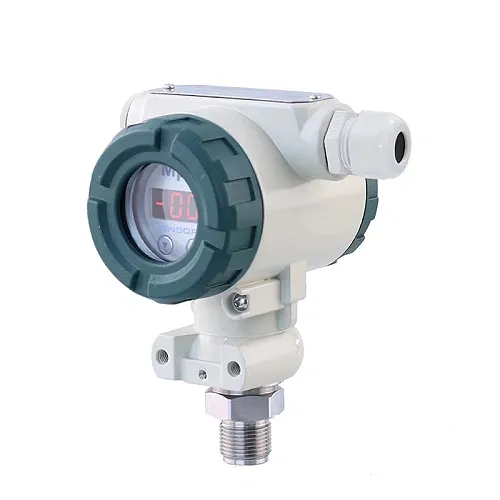
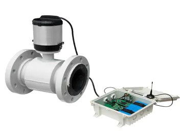
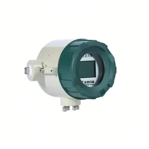
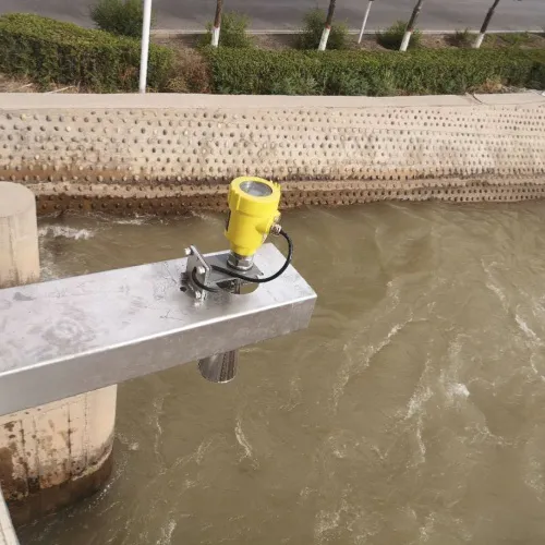
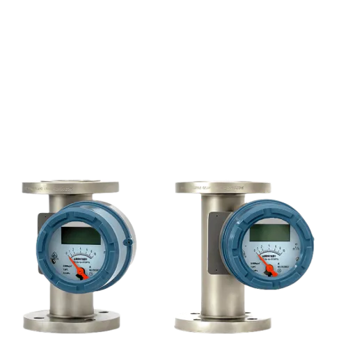
electromagnetic flowmeter meter sensor is provided by the excellent flowmeter and flowmeter production and quotation manufacturers. The split electromagnetic flowmeter sensor is characterized by a volume flow measuring instrument. The split electromagnetic flowmeter consists of two parts: the sensor and the flow converter. The main components are measuring tube, electrode, excitation coil, iron core and yoke, and shell. pass. For more flowmeter manufacturers to select models and price quotations, you are welcome to inquire. The following is the details of the installation guide of the split electromagnetic flowmeter meter sensor. The split electromagnetic flowmeter sensor is characterized by a volume flow measuring instrument. The split electromagnetic flowmeter consists of two parts: the sensor and the flow converter. The main components are measuring tube, electrode, excitation coil, iron core and yoke, and shell. The measuring tube of the sensor is a short tube of non-magnetic conductive alloy lined with insulating material. The fluid to be measured must be a conductive liquid or slurry, and the fluid to be measured should not contain many ferromagnetic substances or bubbles. The corresponding pressure level, Lining materials, electrode materials and instruments. During the measurement process, it is not affected by the temperature, viscosity, density and conductivity of the measured medium (within a certain range). Only after being calibrated by the liquid calibration equipment, it can be used to measure the flow of other conductive liquids, so the installation of the sensor is particularly important, mainly to do the following requirements; the preferred split type electromagnetic flowmeter sensor for the installation point The upstream and downstream straight pipe sections have certain requirements, otherwise the measurement accuracy will be affected. If there is a reducer pipe upstream of the sensor installation point, there should be a straight pipe section of equal diameter not less than 15D upstream of the sensor, and a straight pipe section with equal diameter not less than 5D downstream. If there is a gradually expanding pipe upstream of the sensor installation point, there should be an equal diameter straight pipe section not less than 18D upstream of the sensor, and an equal diameter straight pipe section not less than 5D downstream. If there is 90 upstream of the sensor installation point°For elbows or lower joints, the upstream of the sensor should have an equal diameter straight pipe section of not less than 20D, and the downstream should have an equal diameter straight pipe section of not less than 5D. If the upstream of the sensor mounting point has two 90°For elbows, the upstream of the sensor should have an equal diameter straight pipe section of not less than 25D, and the downstream should have an equal diameter straight pipe section of not less than 5D. If the upstream of the sensor mounting point has two 90°For elbows, the upstream of the sensor should have an equal diameter straight pipe section not less than 40D, and the downstream should have an equal diameter straight pipe section not less than 5D. The flow regulating valve or pressure regulating valve should be installed as far as possible beyond 5D downstream of the sensor. If it must be installed upstream of the sensor, there should be an equal diameter straight pipe section of no less than 50D upstream of the sensor, and an equal diameter straight pipe section no less than 5D downstream. Pay special attention to the fact that if a valve is installed near the upstream of the sensor installation point, the valve will be opened and closed continuously, which will greatly affect the service life of the sensor, and it is very easy to cause permanent damage to the sensor. The sensor should try to avoid installing the sensor on a very long overhead pipeline. After a long time, the sagging of the sensor will easily cause the sealing leakage between the sensor and the flange. If it is installed as a last resort, it must be installed at the upstream and downstream 2D of the sensor. Pipe fastening device. Installation points for split electromagnetic flowmeter The sensor of the split electromagnetic flowmeter should be installed vertically, and the fluid flows from bottom to top to meet the condition that solid and liquid are in a mixed state. The reason is that if there are solids in the medium (silt, small stone particles, etc.), precipitation is likely to occur. In addition, if there are fish and weeds in the pipeline, the fish swimming in the pipeline will cause the output of the flowmeter to swing back and forth; the swinging of the weeds hanging near the electrode will also cause the output of the flowmeter to be unstable. Install a metal screen at the upstream inlet of the flowmeter to block fish and weeds from entering the measuring tube. The split-type electromagnetic flowmeter prevents the negative pressure pipeline setting and improper operation will cause negative pressure in the sensor. When closing the upstream and downstream valves of the flowmeter at the same time, if the temperature of the fluid is higher than the air temperature. It shrinks after cooling, so that the pressure inside the tube is in danger of forming a negative pressure. Negative pressure causes the liner to peel off from the metal conduit, causing electrode leakage. Add a negative pressure prevention valve near the split electromagnetic flowmeter, and open the valve to connect to atmospheric pressure to prevent negative pressure from being generated in the sensor. When a vertical pipe is connected downstream of the split electromagnetic flowmeter, if the upstream valve of the flow sensor is used to close or adjust the flow, a negative pressure will be formed in the measuring pipe of the sensor. To prevent negative pressure, apply back pressure or use downstream valves to regulate and shut off flow. Appropriate maintenance space for split electromagnetic flowmeters. Large-diameter flowmeters are often installed in instrument wells. For the convenience of pipeline installation, wiring, inspection and maintenance, appropriate space needs to be reserved. For the convenience of observation, wiring and maintenance, the instrument should be installed at a certain height from the ground to facilitate cleaning and installation. Now let's talk about how to better install and use the LDG type split electromagnetic flowmeter produced by the city. Correct installation of the flowmeter can achieve twice the result with half the effort, and the flow measurement is more accurate and reliable.
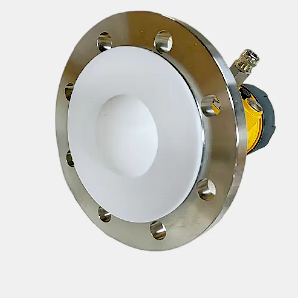
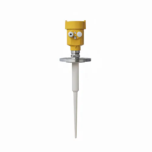
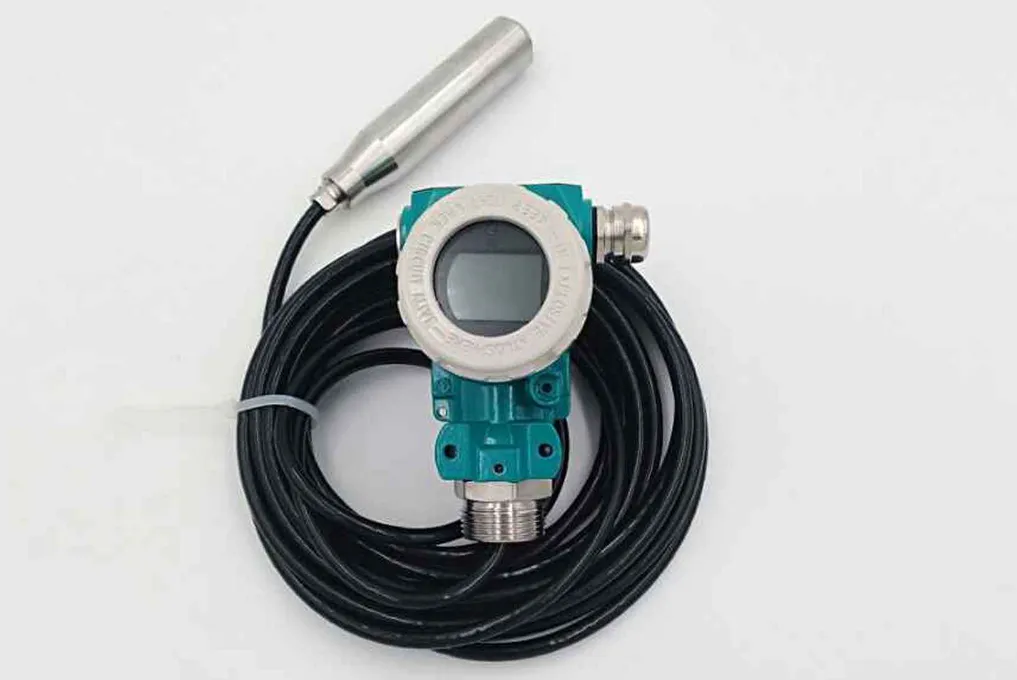
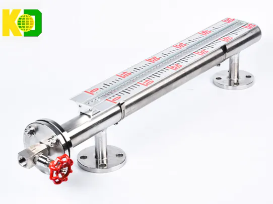
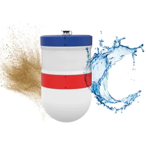
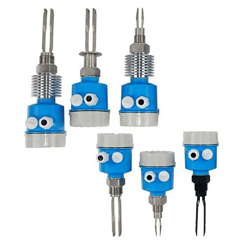
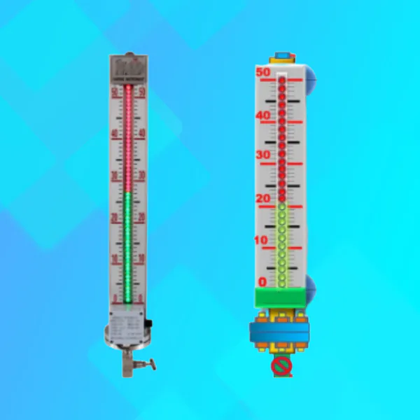
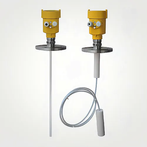
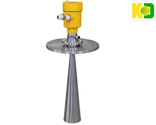
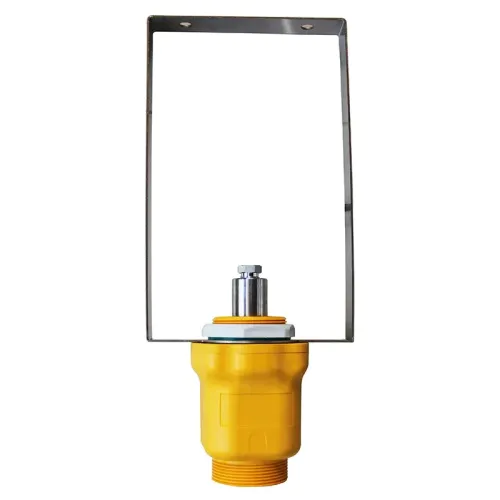
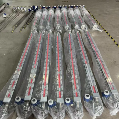
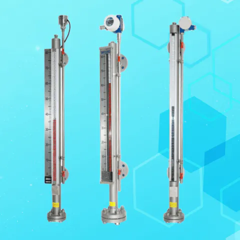
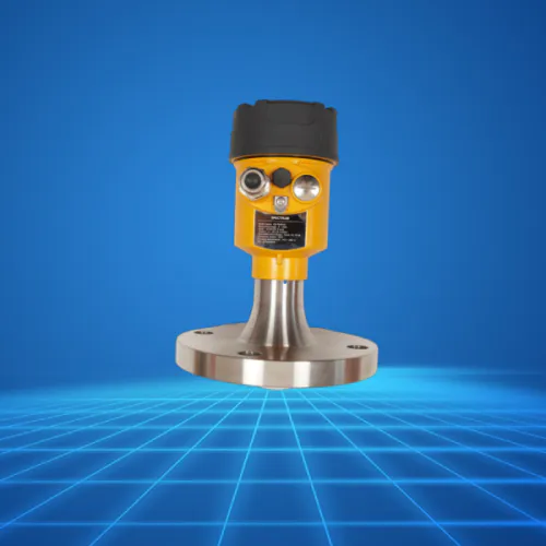
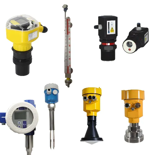
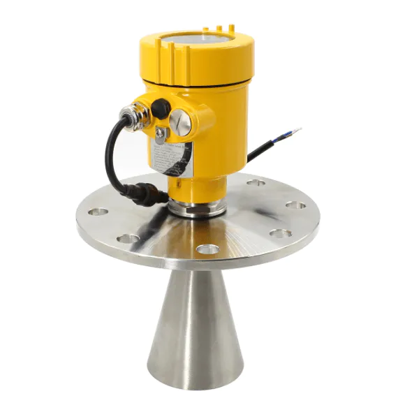
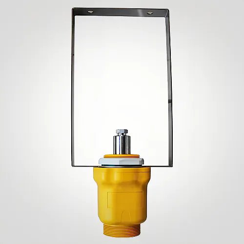
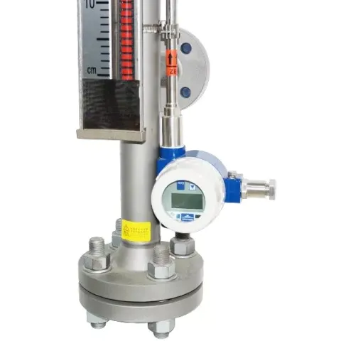
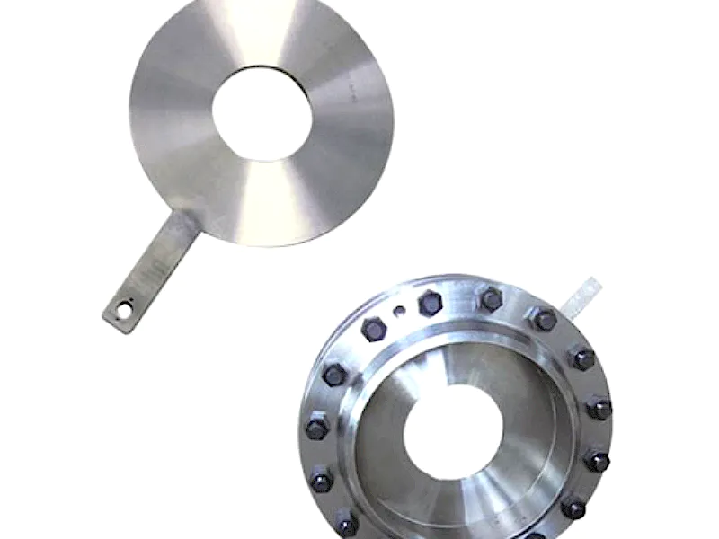
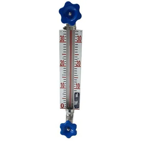
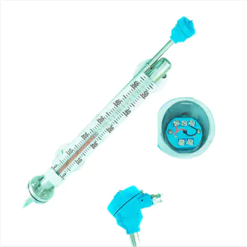
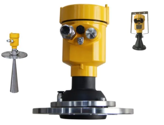
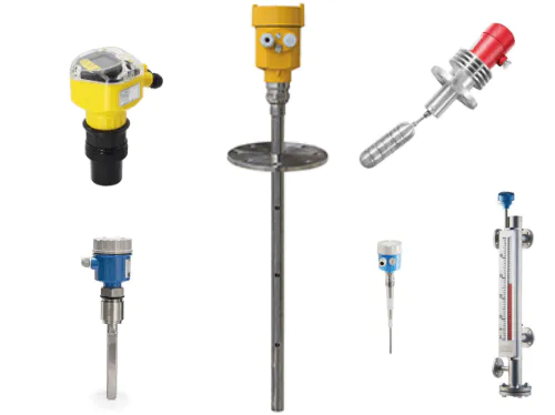
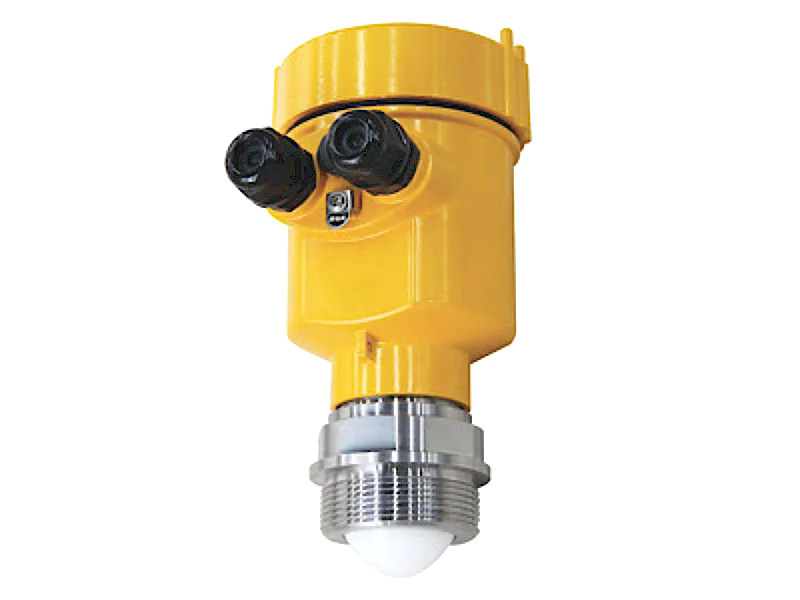
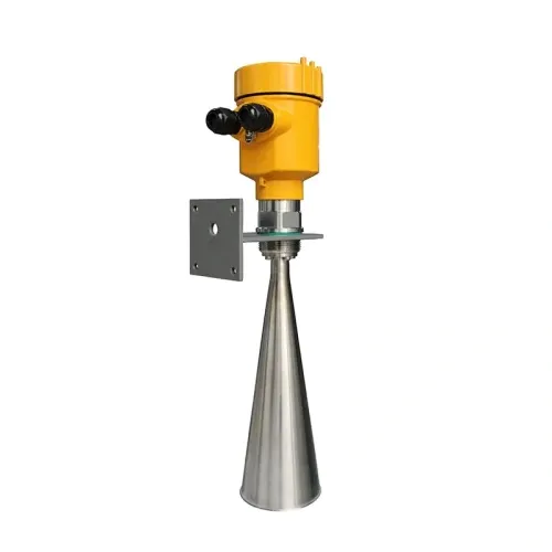
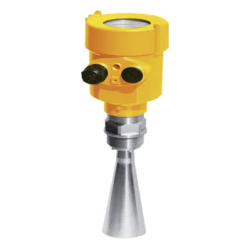
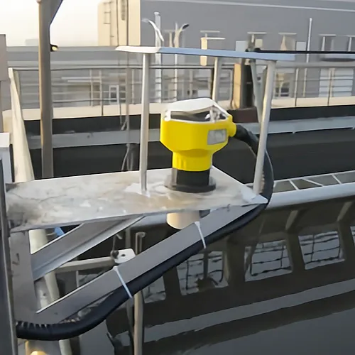
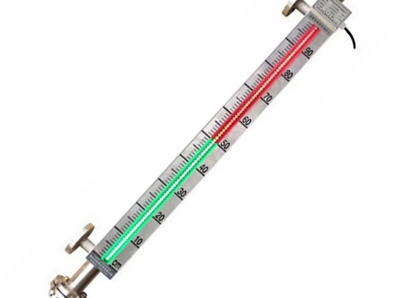
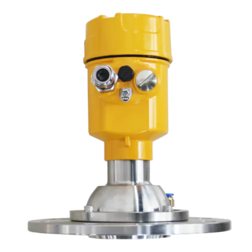
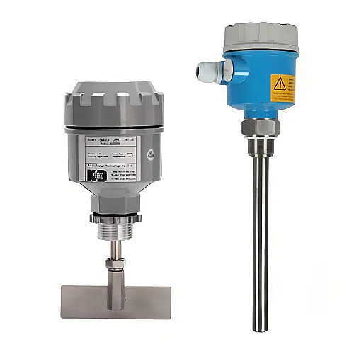
Professional customized level indicator also understand that when you're working with customized level indicator product, it's important to understand that quality of level gauge always matters.
Do you want customized level indicator level gauge? We also have customized level indicator. visit Kaidi level indicator to know more.
These customized level indicator level gauge have made the life easier. The best feature of the is its customized level indicator.
Guangdong Kaidi Energy Technology Co., Ltd. provides a way for you to understand your customers, to learn what makes them unique and what motivates their behavior. We can then leverage that wealth of information to personalize our interactions and demonstrate that level gauge is valuable to our customers.
 Español
  pусский
  العربية
  Português