BETTER TOUCH BETTER BUSINESS
Contact Sales at KAIDI.
Installation precautions and troubleshooting techniques for temperature instruments
Installation precautions for temperature instruments
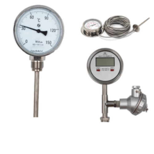
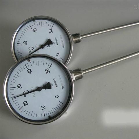
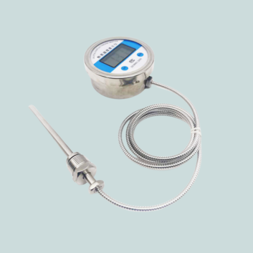
① The installation position of the temperature primary point should be selected in a location where the medium temperature changes sensitively, and should not be selected near resistance components such as valves and welds, or at dead corners of the medium flow beam. The local indicating thermometer should be installed in a convenient location for observation. The installation location of thermocouples should be away from the magnetic field. If the temperature primary component is installed at a bend or inclined position in the pipeline, it should be installed against the flow direction. When installing bimetallic thermometers on pipelines ≤ DN50 or thermal resistors or thermocouples on pipelines ≤ DN70, expansion pipes should be installed. The temperature bulb of a pressure type thermometer must be completely immersed in the measured medium.
② The temperature secondary meter should be used in conjunction. Thermal resistors and thermocouples should be equipped with corresponding secondary meters or transmitters. Pay special attention to the graduation number, and tables with different graduation numbers should not be misused.

③ Thermocouples must use compensating wires with corresponding graduation numbers. The thermal resistor should adopt a three-wire connection method to offset the impact of environmental temperature. Each type of secondary meter has its own requirements for external line resistance. In addition to compensating for the line resistance of wires or cables, manganese copper wire must also be used to match the corresponding resistance to meet the requirements of the secondary meter.
④ Resistors usually use three cores from a three core or four core cable, and the resistance value of each core can be measured using the following method.
⑤ Compensation wires or cables are connected to thermocouples or thermal resistors through metal flexible pipes.
⑥ If there are both pressure and temperature primary points on the same pipeline, the pressure primary point should be located upstream of the temperature primary point.
⑦ The installation of temperature transmitter is relatively simple. Install the qualified secondary meter after individual calibration on the specified instrument panel or frame according to the installation instructions. Temperature secondary meters are a type of display instrument that has developed rapidly in recent years. Most pointer indicating secondary meters (i.e. dynamic coil indicators) have gradually been replaced by digital display temperature meters with completely consistent external dimensions. But there hasn't been much change in installation.

Maintenance tips for temperature instrument malfunctions
The system instruments mostly use electric instruments for measurement, indication, and control.
The measurement of instruments in this system often lags behind significantly.
(1) The sudden change in the indicated value of the temperature instrument system to the maximum or minimum limit is generally a malfunction of the instrument system. Due to the large measurement lag of the temperature instrument system, sudden changes will not occur. At this point, the fault causes of the precession vortex flowmeter are mostly caused by broken thermocouples, thermal resistors, compensation wires, or transmitter amplifier failure.
(2) The temperature control instrument vortex flow meter system indicates rapid oscillation, which is mostly caused by improper PID adjustment of the control parameters.

(3) The significant and slow fluctuations in the temperature control instrument system indications are likely caused by changes in process operations. If there were no changes in process operations at that time, it is likely a malfunction of the instrument control system itself.
(4) Fault analysis steps for the temperature control system orifice flowmeter itself: check if the input signal of the regulating valve changes, if the input signal does not change, if the regulating valve acts, and if the diaphragm of the regulating valve diaphragm head leaks; Check if the input signal of the instrument with the fixed position of the regulating valve changes, the input signal does not change, the output signal changes, and the instrument with the fixed position has a malfunction; Check for changes in the input signal of the fixed position instrument, and then check for changes in the output of the regulator. If the input of the regulator does not change and the output changes, it is a fault of the regulator itself.
We are here to help you! If you close the chatbox, you will automatically receive a response from us via email. Please be sure to leave your contact details so that we can better assist