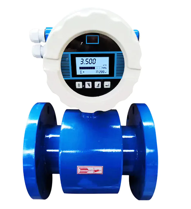
Abstract: The information on how to correctly install the intelligent electromagnetic flowmeter is provided by the excellent flowmeter and flowmeter manufacturers. 1. Requirements for the installation site Generally, the electromagnetic flow
sensor shell protection is extremely IP67, and the following requirements are required for the installation site. 1) When measuring mixed-phase fluids, choose a place that will not cause phase separation; when measuring two-component liquids, avoid installing them in a place where the mixture has not been evenly mixed. More flowmeter manufacturers choose models and price quotations. You are welcome to inquire. The following is the article details on how to correctly install the intelligent electromagnetic flowmeter. 1. Requirements for the installation site Generally, the protection of the electromagnetic flow sensor shell is extremely IP67, and the following requirements are required for the installation site. 1) When measuring mixed-phase fluids, choose a place that will not cause phase separation; when measuring two-component liquids, avoid installing them downstream where the mixing is not uniform; when measuring chemical reaction pipelines, install them downstream of the fully completed reaction section; 2 ) Avoid negative pressure in the measuring tube as much as possible; 3) Choose a place with little vibration, especially for integrated instruments; 4) Avoid large motors, large transformers, etc. nearby, so as to avoid electromagnetic field interference; 5) It is easy to realize the independent grounding of the sensor 6) Avoid high concentrations of corrosive gases in the surrounding environment as much as possible; 7) The ambient temperature is in the range of -25/-10~50/600℃, and the temperature of the integrated structure is also limited by the electronic components, so the range should be narrower 8) Avoid direct sunlight as much as possible; 2. Requirements for installing straight pipe sections First of all, pay attention to the fact that the sensor itself cannot be used as a load support point, it cannot support the adjacent working pipeline, and the pipeline that clamps it should be load-bearing. In order to obtain normal measurement accuracy, there should also be a certain length of straight pipe upstream of the electromagnetic flow sensor, but its length is lower than that of most other flow meters. 90o elbow, T-shaped pipe, concentric reducer, and a straight pipe section with a length of 5 times the diameter (5D) from the flange connection surface at the inlet end of the sensor after the fully open gate valve, and 10D for valves with different opening degrees; the downstream straight pipe section is (2 to 3) D; but it is necessary to prevent the butterfly valve from protruding into the measuring tube of the sensor. The lengths of upstream and downstream straight pipe sections proposed by various standards or verification regulations are also inconsistent, and some electromagnetic flowmeters have higher requirements than usual. This is to ensure that the current 0.5 class accuracy instrument requirements are met. 3. Installation position and flow direction The installation direction of the sensor can be horizontal, vertical or inclined (the fluid must flow horizontally or inclined upward) without restriction. But make sure that the measuring tube is coaxial with the process pipeline. The deviation of its axis shall not exceed 2MM. When measuring solid-liquid two-phase fluids, it is best to install vertically and flow from bottom to top. This can avoid serious local wear of the lower half of the lining during horizontal installation, and solid phase precipitation at low flow rates. When the sensor is adjacent to the pipeline for welding or flame cutting, isolation measures should be taken to prevent the lining from being heated, and it must be confirmed that the signal line of the instrument converter is not connected to prevent damage. When the converter is installed horizontally, the axis of the electrode should be parallel to the horizon, not perpendicular to the For the horizon, because the electrode at the ground is easily covered by sediment, the top electrode is easily wiped by the occasional air bubbles in the liquid to cover the surface of the electrode, causing the output signal to fluctuate. 4. The installation of negative pressure piping systems Fluoroplastic lined sensors must be carefully applied to negative pressure piping systems; positive pressure piping systems should prevent negative pressure, such as piping systems with liquid temperature higher than room temperature, close the upstream and downstream stop valves of the sensor to stop running After the fluid cools and contracts, a negative pressure will be formed. A negative pressure prevention valve should be installed near the sensor. The manufacturer stipulates that the pressure of PTFE and PFA plastic lining applied to the negative pressure piping system can be used at 200C, 1000C, and 1300C. The absolute pressure must be For non-conductive pipes, respectively, the grounding flange is clamped between the sensor flange and the pipe flange. 5. The grounding sensor must be grounded separately (grounding resistance 10Ωthe following). In principle, the grounding of the separate type should be on the sensor side, and the grounding of the converter should be at the same grounding point. If the sensor is installed on a pipeline with cathodic corrosion protection, in addition to grounding the sensor and the grounding ring together, a thicker copper wire (16mm) should be used to bypass the two connecting flanges of the sensor across the pipeline, so that the cathodic protection current flows between the sensors. isolation. Sometimes the stray current is too large. If the leakage current of the electrolytic cell along the electrolyte affects the normal measurement of EMF, the method of electrical isolation between the flow sensor and the process to which it is connected can be taken. This method can also be used when the cathodic protection current affects the EMF measurement on pipelines with cathodic protection as well. Second, the installation specification of the converter and its accessories 1. The length of the signal cable between the converter and the sensor cannot be greater than 50M, and the signal cable must be sheathed with galvanized pipe. If the galvanized pipe is in the air, the galvanized pipe should be grounded reliably with a wire, the grounding resistance is less than 10 ohms 2, the power supply is 220v one-way AC, an air switch is installed in the instrument box, the arrester and the air switch are connected in parallel, and the wire is connected from the air After the switch comes out, connect a three-way socket 3. Arrester grounding The arrester grounding wire should not exceed 1M in length and the cross-sectional area should be larger than 6MM square multi-strand copper core insulated wire. If there is no ground net nearby, a simple ground net should be made near the arrester. The method is as follows: use three flat steel or angle steel with a length of 1.5M, drive them into the ground in a regular triangle arrangement, and weld the three flat steel with flat steel bars on the top. , Weld bolts in one corner, and then connect the arrester grounding wire to install the panel on the ground plane of the 220V AC lightning arrester grounding wire. The above is the whole content of this article. You are welcome to inquire about the flowmeter selection and quotation of our factory. 'How to correctly install the intelligent electromagnetic flow meter'
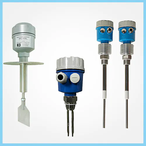
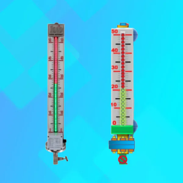
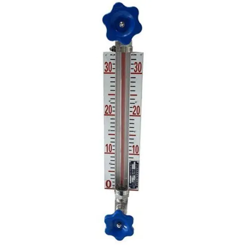
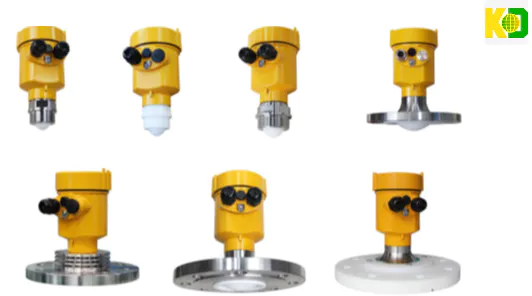
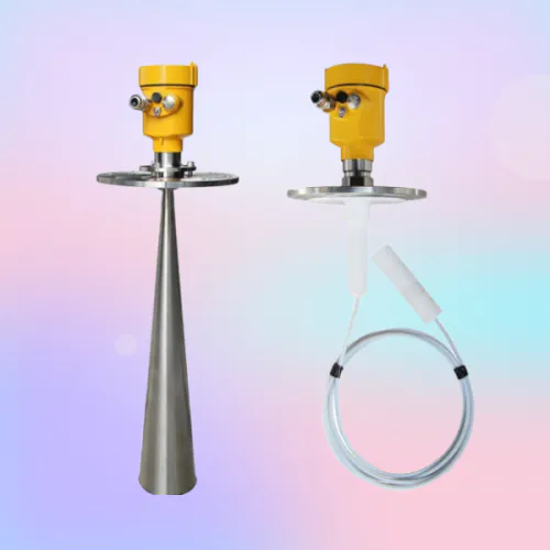
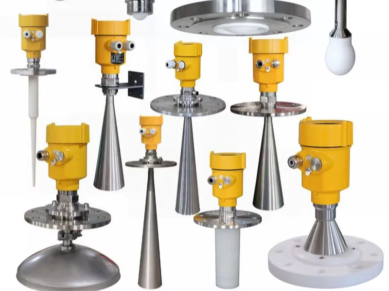
These level gauge customized level indicator are meant to serve as a guide for business owners on how to both identify potential opportunities for transformative innovation and how to adapt to the constantly changing technologies of today.
Guangdong Kaidi Energy Technology Co., Ltd.’s core aim is to afford high-quality products with the concept of manufacturing technology.
The engineers and developers of Guangdong Kaidi Energy Technology Co., Ltd. are the best in their own professional way and we guarantee to provide related service to our dear customers.
The trend toward using customized level indicator level gauge to ease customized level indicator, once established, soon extended into such additional fields as customized level indicator and customized level indicator.
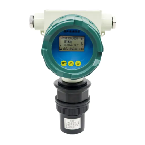
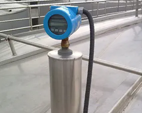
level gauge can be great additions to companies looking to improve the well-being of their employees, as well as increase the efficiency and productivity of their workers across the organization.
 Español
  pусский
  العربية
  Português