Principle
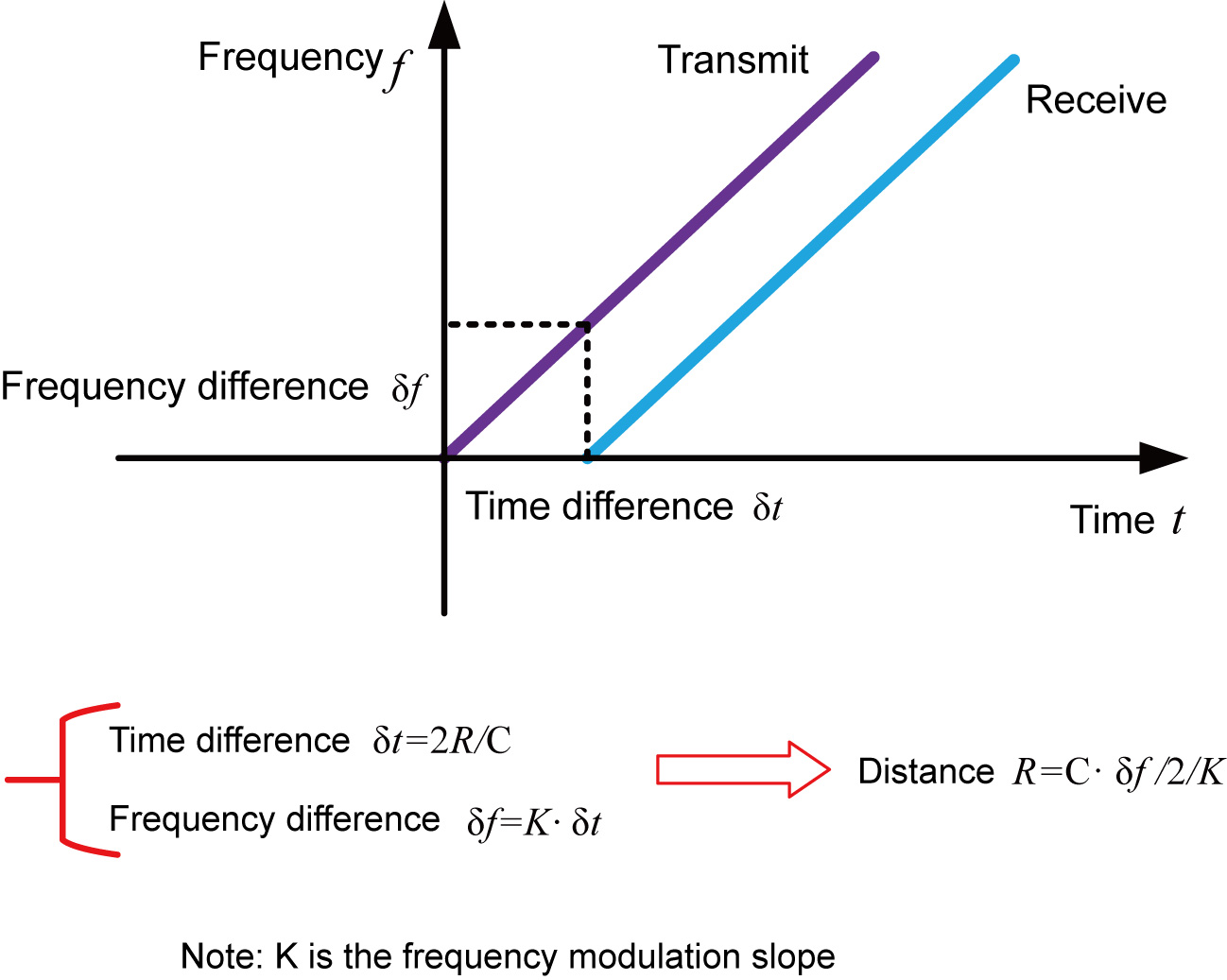
The general principle of high temperature molten salt radar is that the radar emits electromagnetic waves at the top of the tank, and the electromagnetic waves are received by the radar after they encounter the medium reflection. The frequency difference δf between the received signal and the emitted signal is proportional to the distance R to the surface of the medium: R = C (speed) * δf (frequency difference) / 2 / K (FM slope). Because the speed of light C and the FM slope K are known, the frequency difference δf is estimated and the distance R to the material surface at the radar installation position can be obtained, and then the height of the material level is obtained by subtracting the spatial distance from the radar to the material surface (referred to as the empty height) from the known total height of the tank.
Features:
1. millimetre wave radar with a measurement accuracy of up to ±2mm and a minimum blind spot of 0.1m.
2. Smaller antenna size to meet more working conditions measurement.
3. Multiple lens antennas, smaller emission angle, more concentrated energy, stronger echo signal, under the same working conditions, compared to
The radar has a higher reliability than other radar products.
4. stronger penetration, even in the case of adhesion and condensation.
5. greater dynamic signal range for more stable measurements in low dielectric constant media.
6. Multiple measurement modes, with a radar response time of less than 1S in fast measurement mode.
Products
DV-21Product Introducion
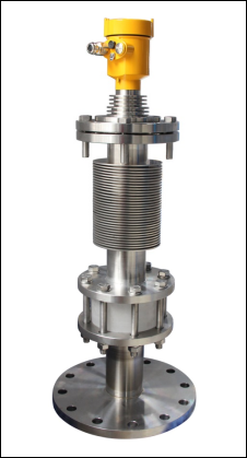 Measuring medium: liquid
Measuring range: 30m
Process connection: Flange ≥ DN80
Process temperature: -40~600℃
Process pressure: -0.1 to 1.0 MPa
Antenna size: 75mm lens antenna + quartz glass insulation
Accuracy: ±2mm
Protection class: IP67
Centre frequency: 80GHz
Emission angle: 3°
Power source: 2-wire/DC24V
Four-wire/AC220V
Housing: Aluminium/plastic/stainless steel
Signal output: 2-wire/4.... .20mA/HART protocol
Installation requirements
Mounting: Flange mounting
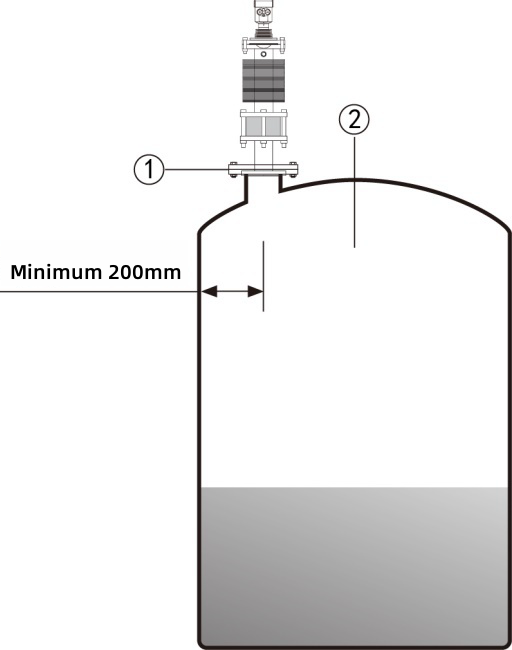
The minimum distance of the instrument from the tank wall should be 200mm when flange mounting is used.
① datum ② centre of the vessel or axis of symmetry
Installation requirements: When installing the instrument avoid installing it above the inlet and try to avoid various objects that affect the
signal, e.g. stirring paddles
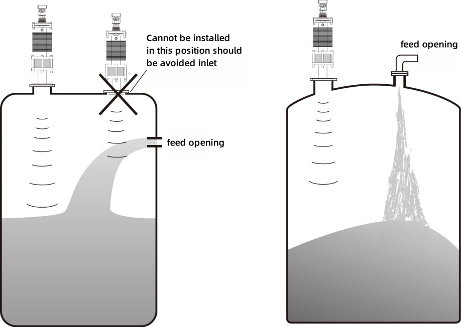
Measuring solids Measuring liquids
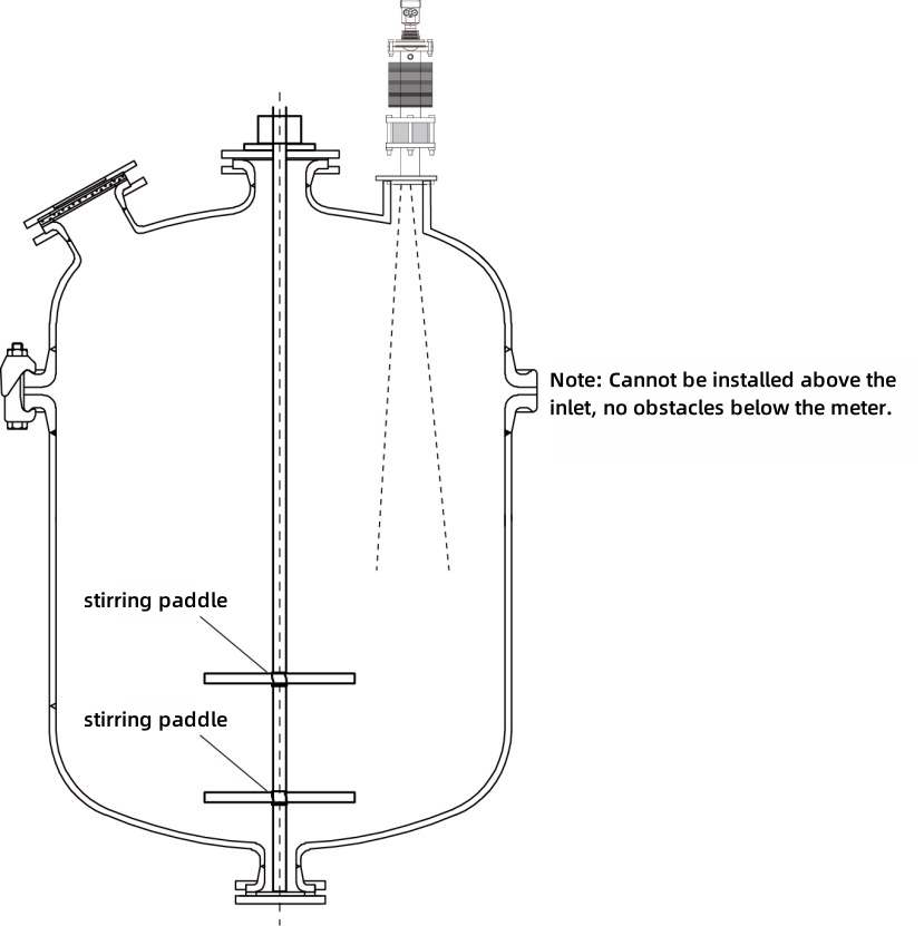
In extremely complex operating conditions, the instrument will function without any obstructions within a 20 cm radius from the radar mounting point.
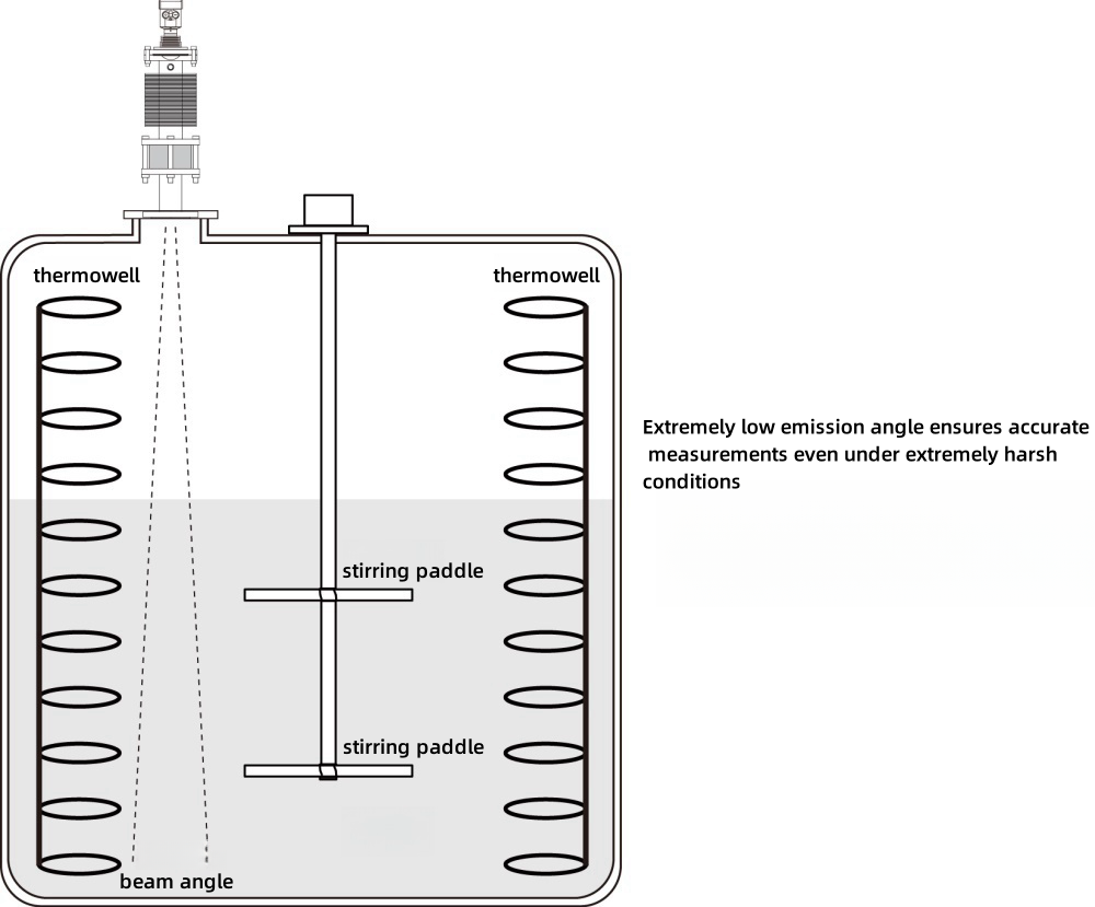
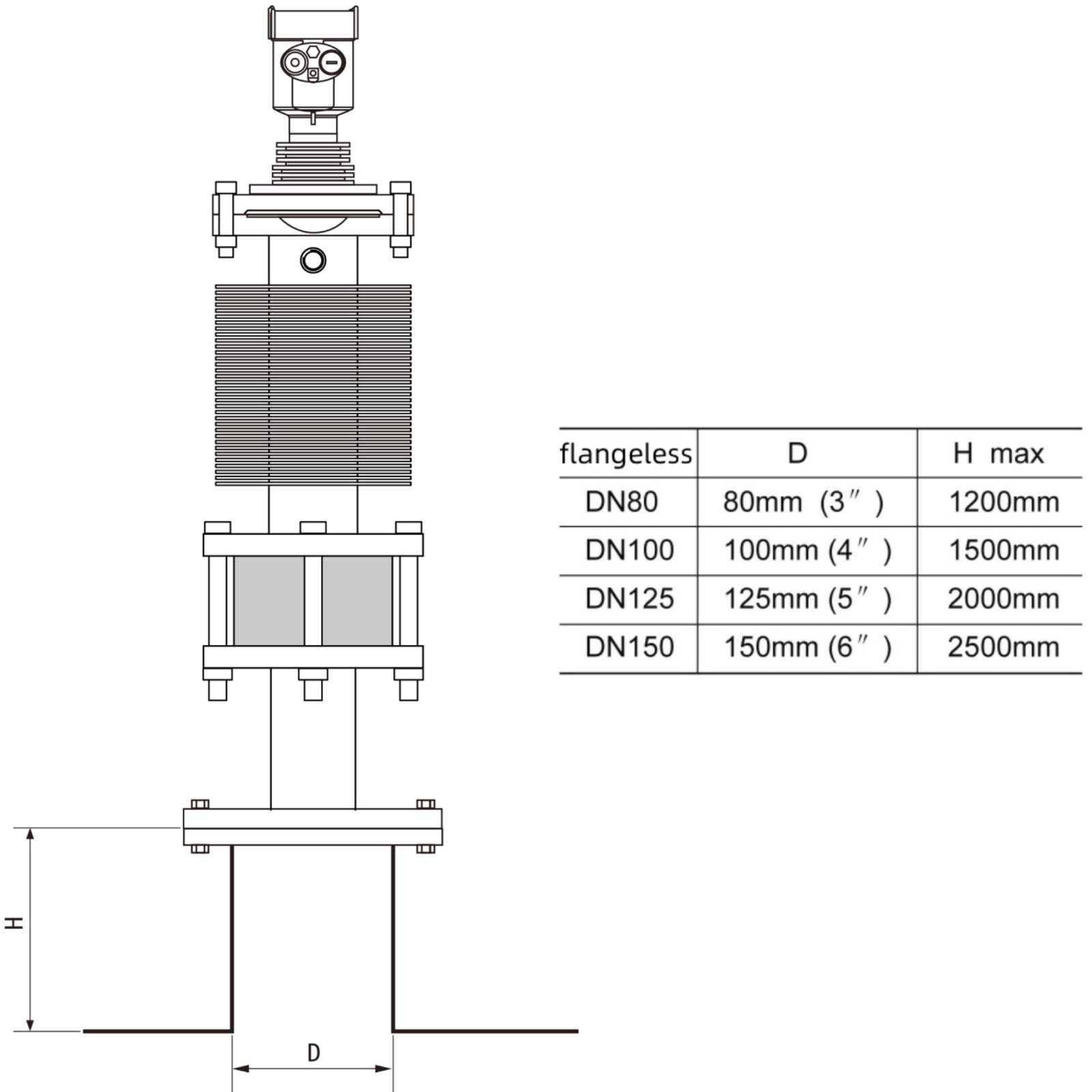
Diagram of the installation receiver
The maximum mounting stub height H max depends on the mounting stub diameter D and the size of the product launch angle.
Excessively long mounting stubs can affect the radar performance.
l Supply voltage
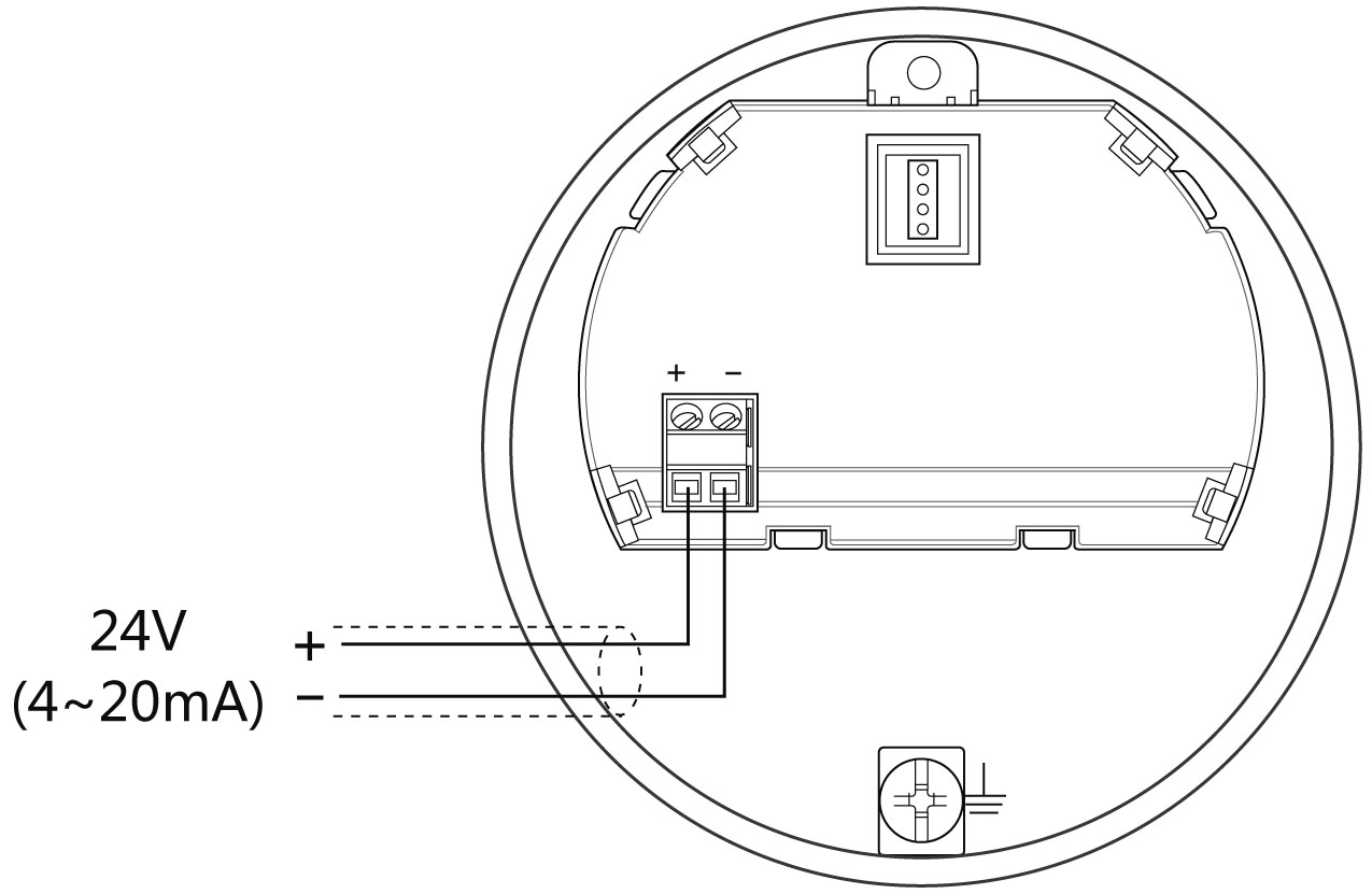
(4 to 20) mA/HART (2-wire system) The supply power and the output current signal share a common two-wire shielded cable line. See technical data for specific supply voltage range.
(4-20) mA (4-wire) The power supply needs to be supplied separately, and the power supply and current signal use a four-core shielded cable (the current signal can be output simultaneously with the RS485 interface; a six-core shielded cable is required for the simultaneous output).
RS485/Modbus The power supply needs to be powered separately and a four-core shielded cable is used for the power and digital (the current signal can be output at the same time as the RS485 interface, a six-core shielded cable is required for the simultaneous output).
l Connection
The 24V two-wire wiring diagram is as follows:
Four-wire, two-room wiring diagram as follows:
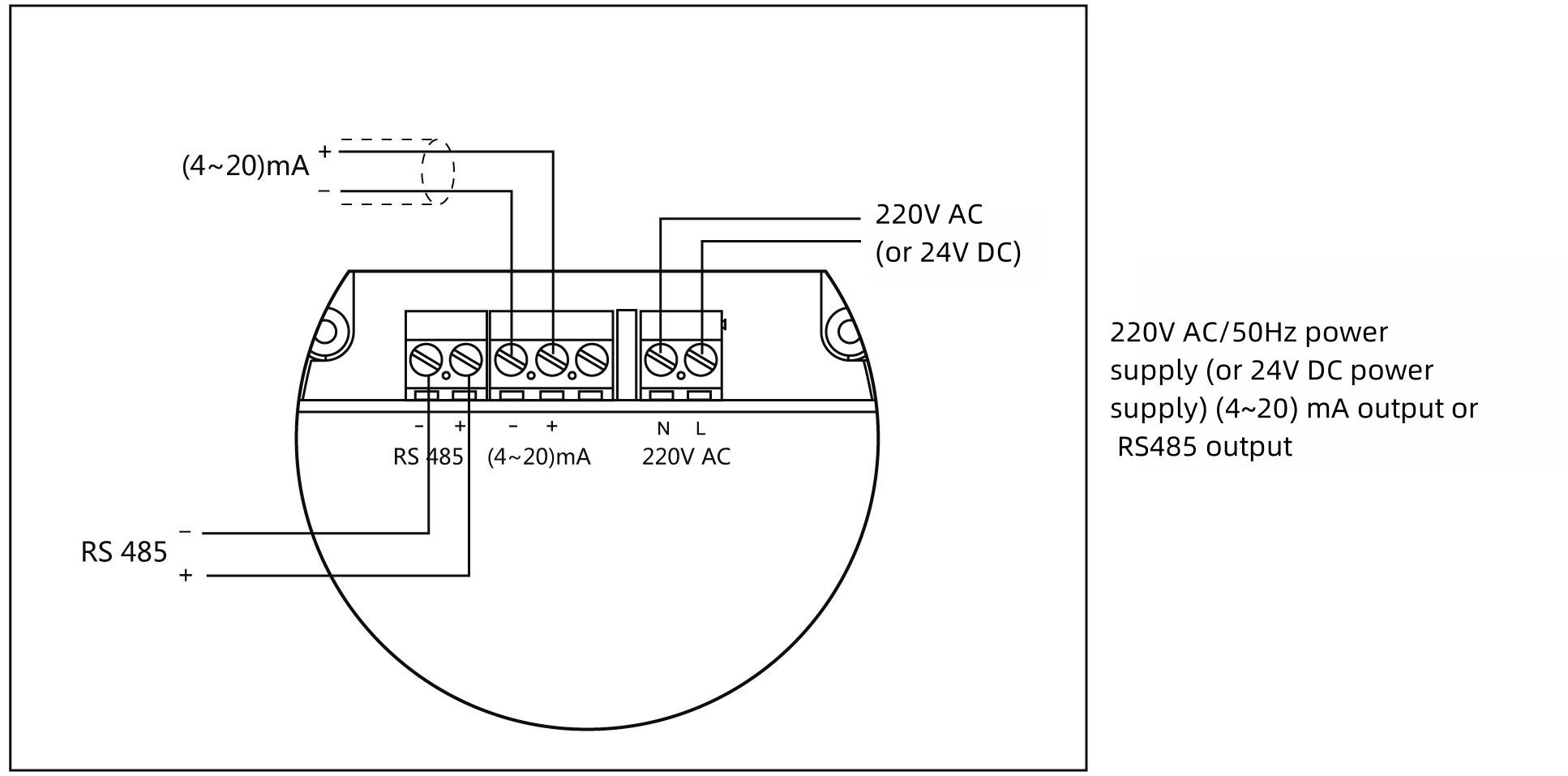
l Safety guidance
Please observe the requirements of the local electrical installation regulations!
Please observe the requirements of local regulations for the health and safety of personnel. All work on the electrical components of the instrument must be carried out by properly trained professionals.
Check the instrument's nameplate to ensure that the product specifications meet your requirements. Make sure that the supply voltage corresponds to the requirements on the instrument's nameplate.
l Protection class
This instrument fully meets the requirements of protection class IP66/67. Please ensure that the cable sealing head is watertight. Picture below:
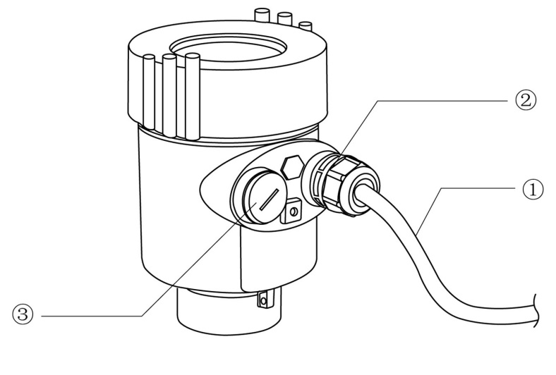
How to ensure that the installation meets the requirements of IP67:
Please ensure that the sealing head is not damaged.
Please ensure that the cable is not damaged.
Please ensure that the cable used meets the requirements of the electrical connection specification.
Before entering the electrical connection, bend the cable downwards to ensure that water does not flow into the housing, see ①
Please tighten the cable sealing head, see ②
Structure dimensions
v Case dimensions (Unit mm)
Cast aluminium case
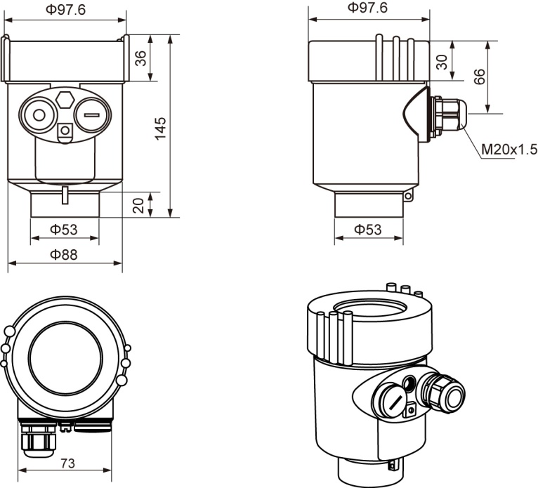
Stainless steel case
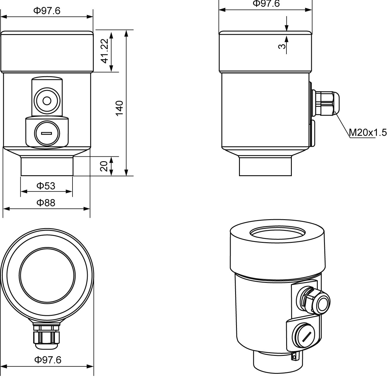
v Product dimensions (Unit mm)

Technical specifications
Process connection Flange / Material 304 stainless steel, PP 304 stainless steel + PTFE flanged
Antenna type PTFE + quartz glass insulation
Housing Cast aluminium / Stainless steel
Sealing between housing and housing cover Silicone rubber
Housing sight glass Polycarbonate
Grounding terminal Stainless steel
Supply voltage
2-wire system (15-28) V DC
Power consumption max 80mA DC24V/ 2W
Allowable ripple <100Hz Uss < lV
(100 to 100K) Hz Uss < l0mV
Dual chamber housing
(198-242) V AC 4-wire
110V AC 4-wire
Cable parameters
Cable entry/plug 1 x M 20xl.5 Cable entry
1 blind plug M20xl.5
Terminal Wire cross section 2.5 mm²
Output parameters
Output signal (4 to 20) mA / HART protocol
Resolution 1 mm
Fault signal Current output constant; 20. 5mA; 22mA; 3.9mA
Integration time (0 to 20)s, adjustable
Blind zone 0.1m/0.2m/0.3m
Max. measuring distance 30 m
Measuring interval approx. 1 s (depending on parameter setting)
Adjustment time approx. 1 sec (depending on parameter setting)
Operating storage and transport temperature (-40 to 600) °C
Relative humidity ˂ 95%
Pressure Max. 1.0 MPa
Vibration resistance Mechanical vibration l0m/s² , (10 to 150)Hz
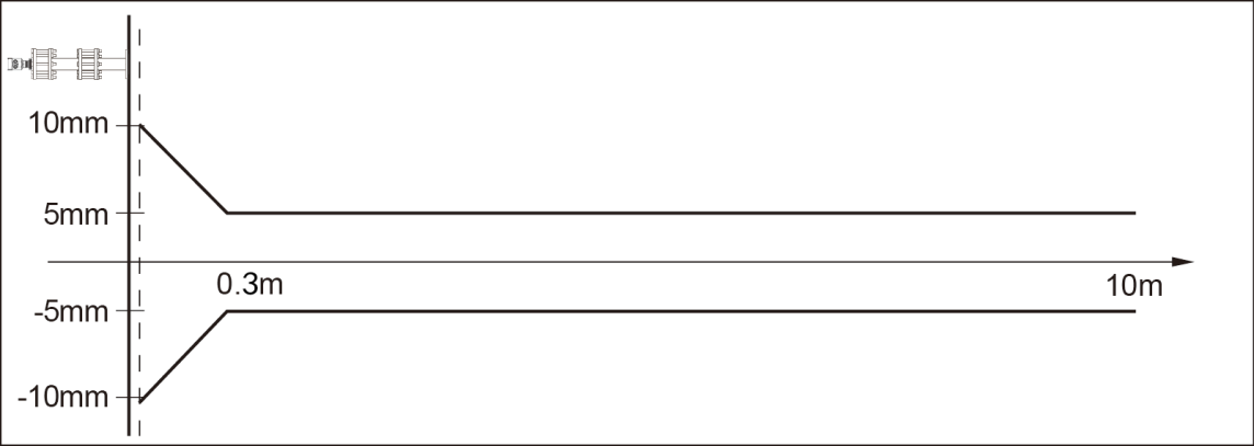
Instrument linearity
Beam angle
The beam angle is the angle of the beam at which the energy density of a radar wave reaches half of its maximum value (3 dB width). The microwave emits a signal beyond the
outside the beam range and can be reflected by interfering objects.
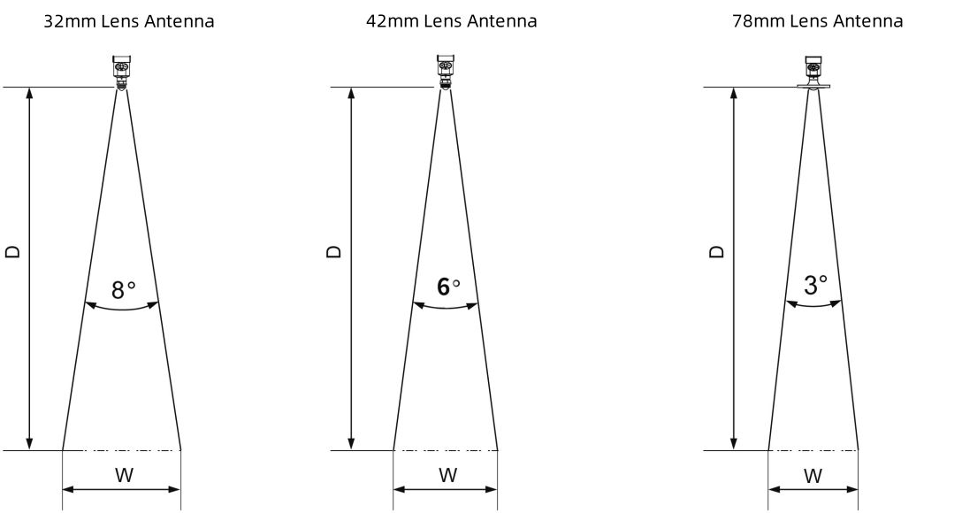
Lens Antenna Diameter | Φ32mm Lens Antenna | Φ42mm Lens Antenna | Φ78mm Lens Antenna |
Beam angle | 8° | 6° | 3° |
The larger the antenna size, the smaller the beam angle α and the less interference echoes are generated.
For more accurate measurements, avoid installing any internal devices (e.g. limit switches, temperature sensors, bases, vacuum rings, heating coils, baffles, etc.) within the signal beam range.
Instrument linearity
High temperature molten salt radar selection
Certifiable |
P Standard (non-explosion-proof) I Intrinsically safe (Exia IIC T6 Ga) D Intrinsically safe + explosion-proof (Exd ia IIC T6 Gb)
|
Process connection |
1 G3.5A thread 2 Flange ≥ DN80 (stainless steel + PTFE) X Special customization |
Flange options/materials | ||||||||||||||||||
| ||||||||||||||||||
Antenna type / material | ||||||||||||||||||
A 78mm lens antenna/PTFE | ||||||||||||||||||
Sealing/process temperature | ||||||||||||||||||
A Asbestos /(-40-400℃) B Asbestos /(-40-600℃) Y Special customization | ||||||||||||||||||
Electronic units | ||||||||||||||||||
1 (4~20) mA/HART protocol 24VDC 2-wire 3 (4~20) mA/HART protocol 220VAC 4-wire | ||||||||||||||||||
Housing material/protection class | ||||||||||||||||||
A Aluminium (single cavity) / IP67 B Aluminium (double cavity) / IP67 C Aluminium (double cavity side view) / IP67 E Stainless steel (304) / IP67 | ||||||||||||||||||
Cable entry | ||||||||||||||||||
M M20x1.5 N 1/2NPT X Special customization |
Display programming |
A Programming with display B with display programming / Bluetooth communication C without |
We are here to help you! If you close the chatbox, you will automatically receive a response from us via email. Please be sure to leave your contact details so that we can better assist