BETTER TOUCH BETTER BUSINESS
Contact Sales at KAIDI.
Application:
6GHz radar level gauge is suitable for liquid, paste, granule and block material level and non-contact measurement, suitable for changes in temperature, pressure big; there is an inert gas and volatile.
The measurement method of microwave pulse, can work normally in the industrial frequency band range. The beam energy is low, can be installed on all kinds of metal, non-metallic container or pipe, no harm to human body and environment.
| Suitable for Medium: | Liquid, especially with pressure and Volatile Liquid |
| Explosion-proof Grade: | Exia IIC T6 Ga/ Exd IIC T6 Gb |
| Measuring Range: | 35m |
| Aerials: | The Horn Antenna |
| Frequency: | 6 GHz |
| Temperature: | (-40 ~ 250) ℃ |
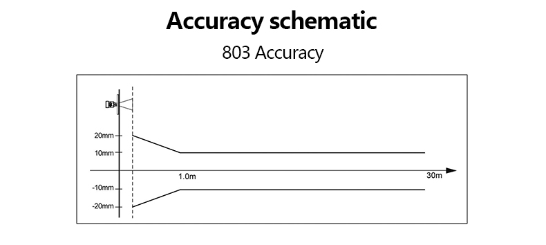
| Measurement Precision: | ±10mm |
| Process Pressure: | (-0.1 ~ 4) Mpa |
| The signal Output: | (4 ~ 20) mA/HART |
| The Scene Display: | Four LCD /Can be programmed |
| Power Source: | Two-wire (DC24V) 、Four-wire (DC24V/AC220V) |
| Repeatability: | ± 1mm |
| Outer Covering : | Aluminum /Plastic |
| Connection: | Flange (optional) |
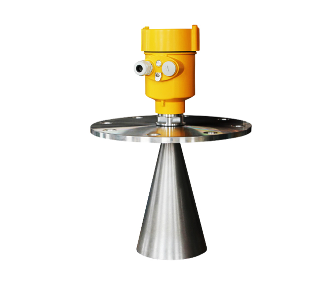
1. Dimensions of Instruments
l Horn antenna size (unit: mm)
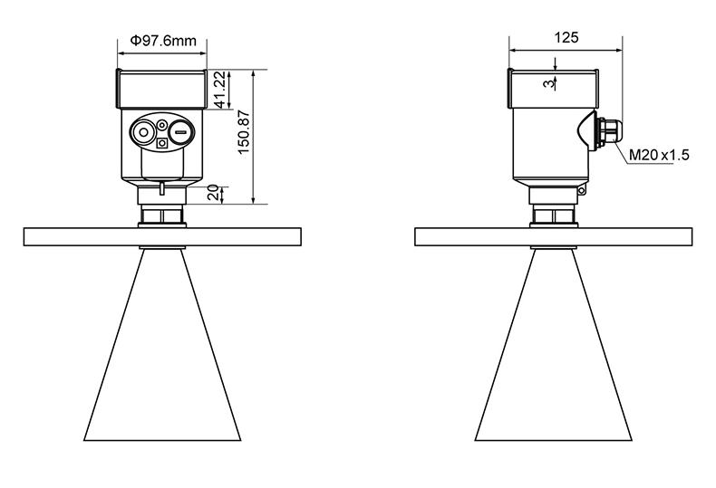
l Horn size (unit: mm)
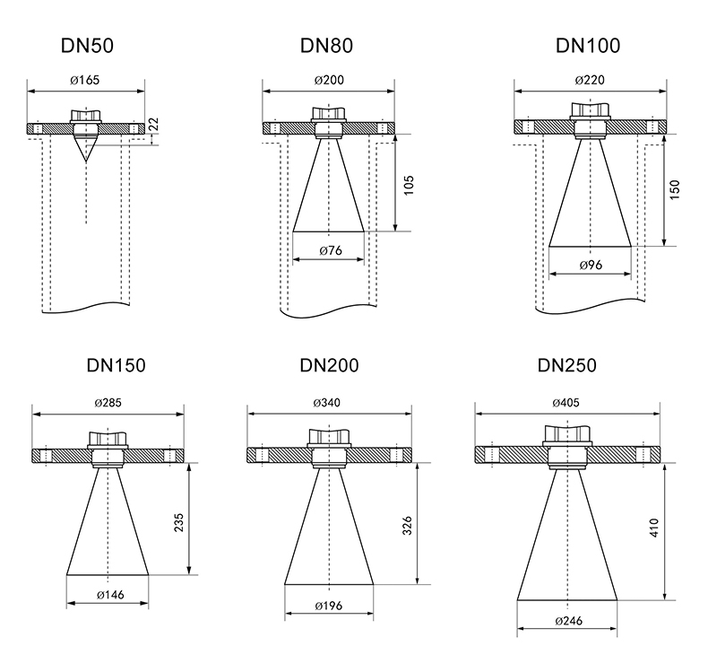
l Flange Selection (unit: mm)
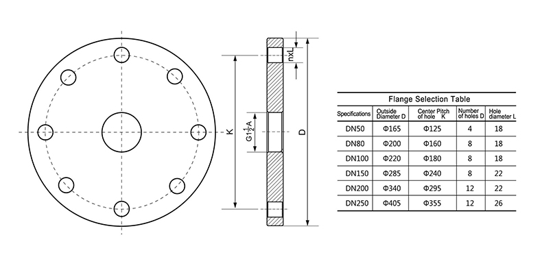
2.The Electrical Connection
l The power supply voltage:
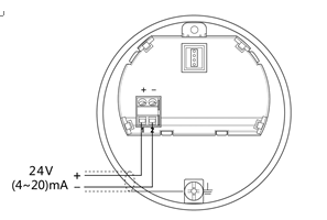
| (4~20)mA/HART (Two wire system) | The power supply and the output current signal sharing a two core shield cable. The supply voltage range see technical data. For intrinsically safe type must be a safety barrier between the power supply and the instrument. |
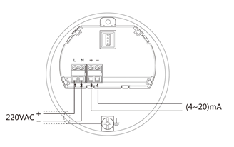
| (4~20)mA/HART(Four wire system) | Separate power supply and the current signal, respectively using a two-core shielded cable. The supply voltage range see technical data. |
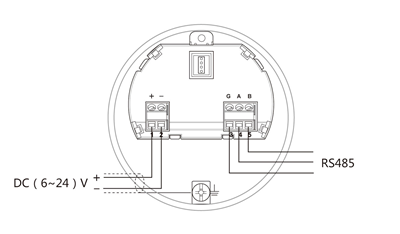
| RS485 / Modbus | Power supply and Modbus signal line are separated, respectively using a two-core shielded cable, the power supply voltage range see technical data. |
l Connection mode:
Ø
24V two wire wiring diagram as follows:
Ø
220V four wire connection is as below:
Ø 24V RS485/Modbus wiring diagram as follows:
3. Programming and Debugging
l Display / Keyboard:
Please debug the instrumentation by four buttons on the display screen. There are three debug menu languages optional. After debugging is generally used only for display, through the glass window can read measured value very clearly.
Display / Keyboard :

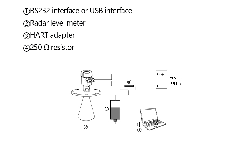
l PC debugging:
Connected to PC by HART:
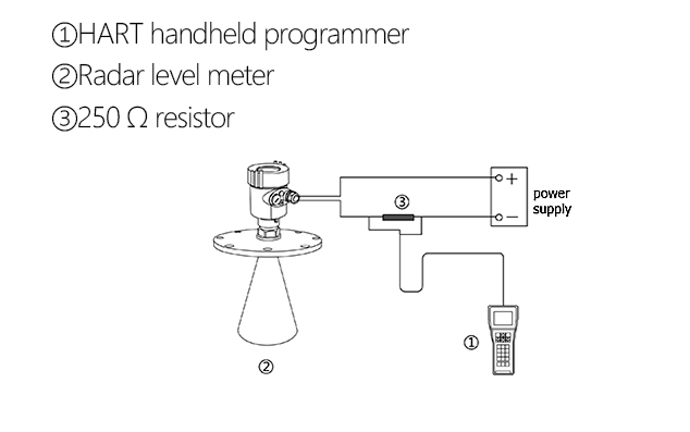
l HART handheld programmer:
4. Technical Parameters
| General data | |
| Materials | |
| Antenna | PTFE, PP |
| Outer Covering | Aluminum, Plastic, Anti-static PP, Stainless steel 316 |
| The seal housing and the housing | Silicone Rubber |
| Shell window | Polycarbonate |
| Ground terminal | Stainless steel |
| Process connection | |
| 803 | Stainless Steel Flanges |
| Supply voltage | |
| Two-wire | |
| Standard | (16~26)V DC |
| Intrinsically Safe | (21.6~26.4)V DC |
| Power Consumption | Max.22.5mA |
| Allowable ripple | |
| <100HzH47 | Uss < lV |
| - (100~100K)Hz | Uss < l0mV |
| Flameproof | |
| (22.8 ~ 26.4) V DC 2-wire system | |
| (198 ~242)V AC 4-wire system / 110V AC 4-wire system | |
| Power Consumption Max. 1VA,1W | |
| Cable parameters | |
| Cable entry / plug | 1 M20xl.5 cable entry (cable diameter 5 ~ 9mm) |
| 1 blind blocking M20xl.5 | |
| Spring terminals | For wire cross-section 2.5mm² |
| Output parameters | |
| The output signal | (4~20)mA / HART |
| Resolution | 1.6μA |
| Fault signal | Current output unchanged;20.5mA;22mA;3.9mA |
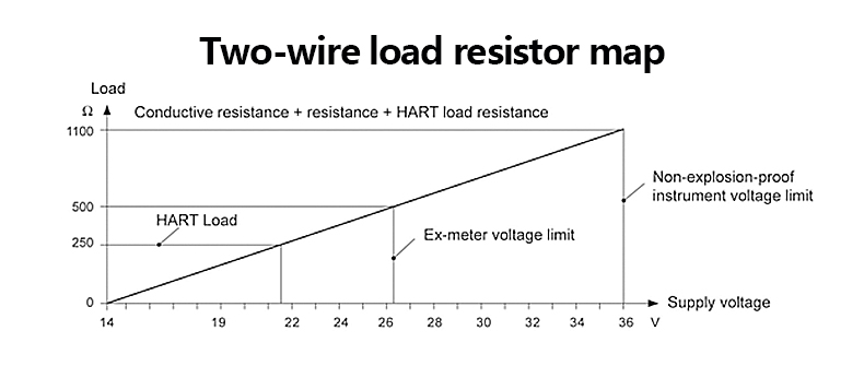
| Two-wire load resistor | See below |
| Four-wire resistive load | The maximum 500Ω |
| Integration time | (0 ~ 36) s, adjustable |
We are here to help you! If you close the chatbox, you will automatically receive a response from us via email. Please be sure to leave your contact details so that we can better assist