Español
  pусский
  العربية
  Português
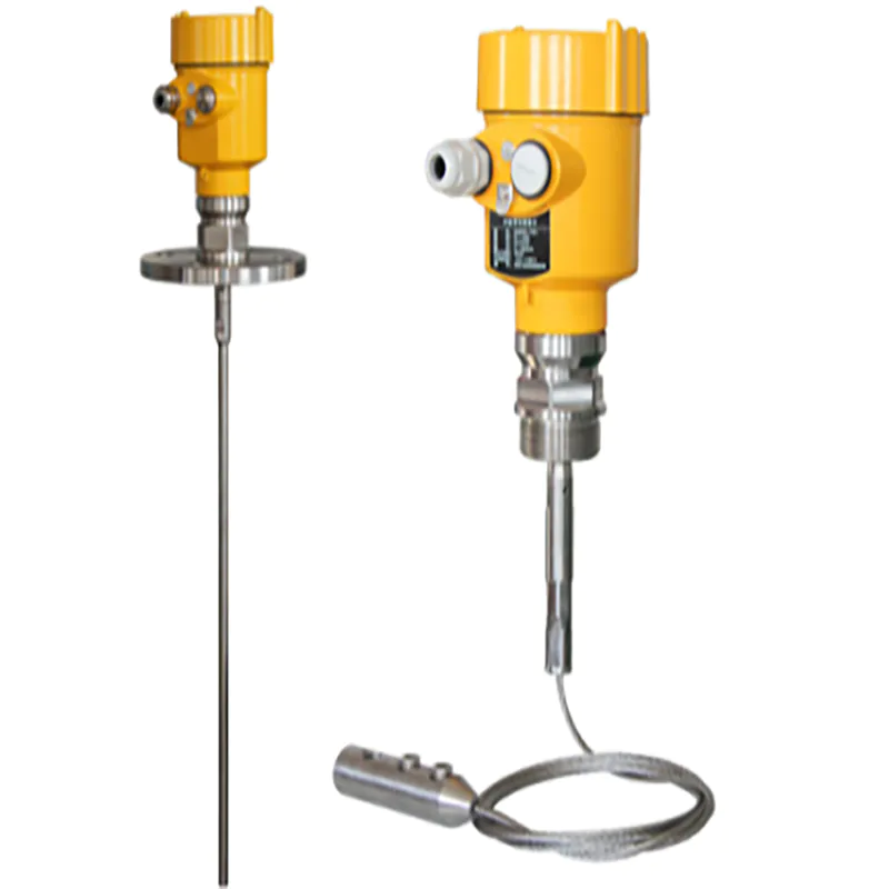
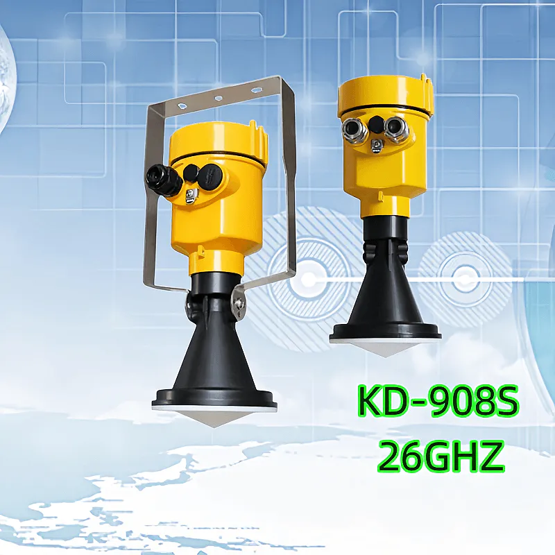
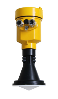
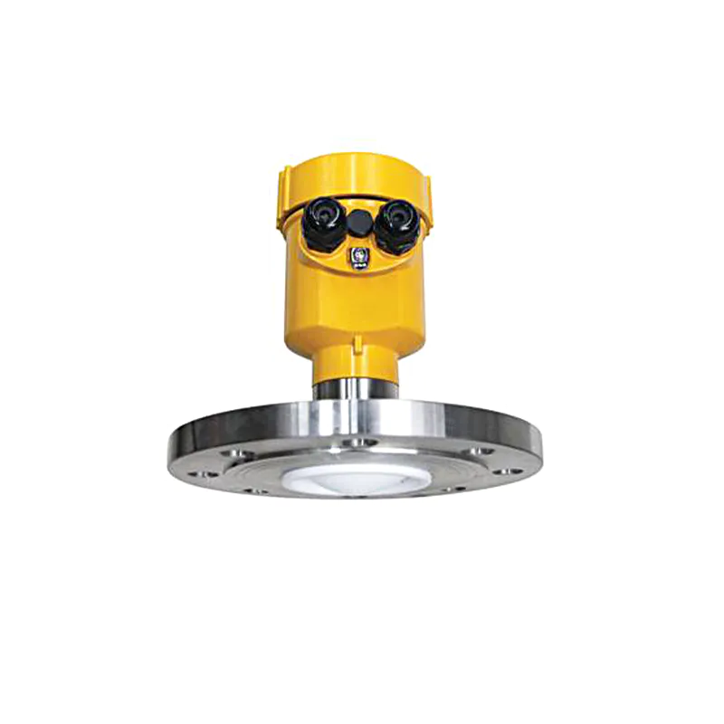
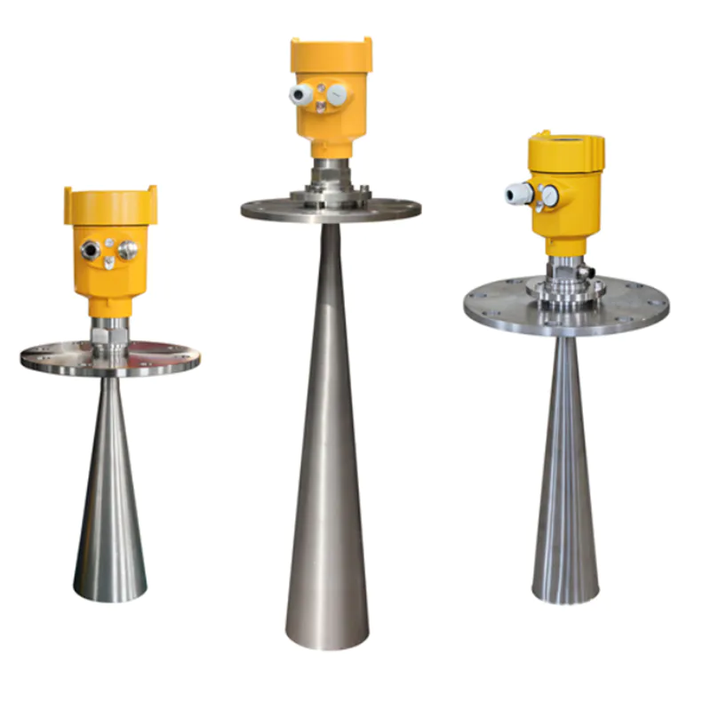
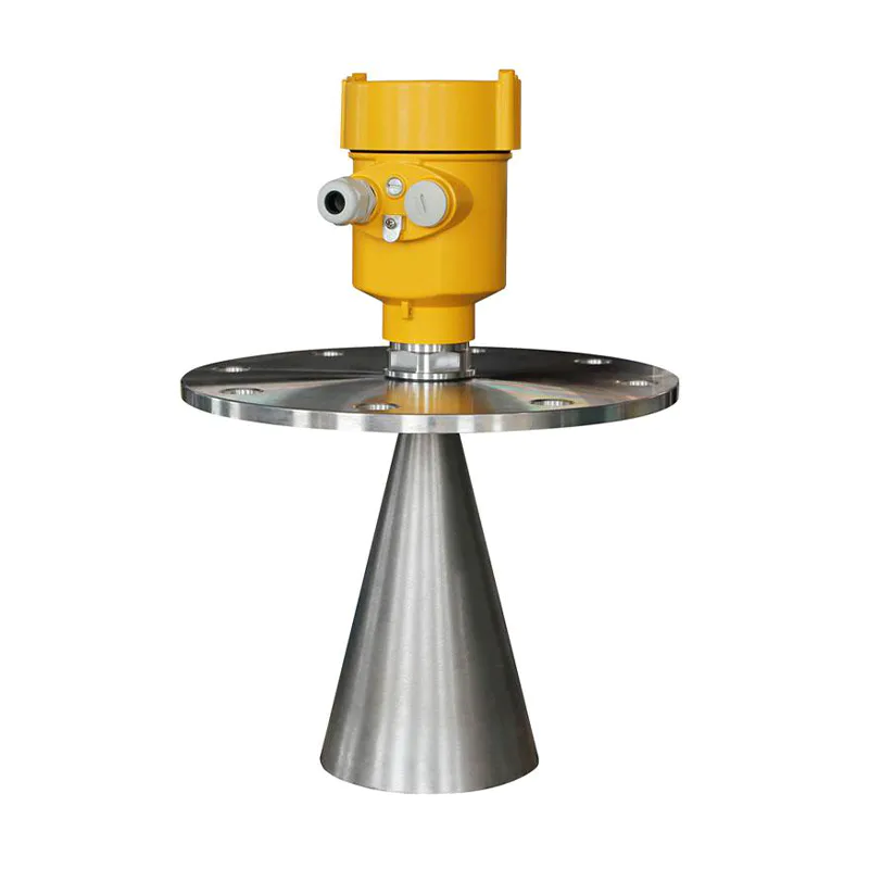
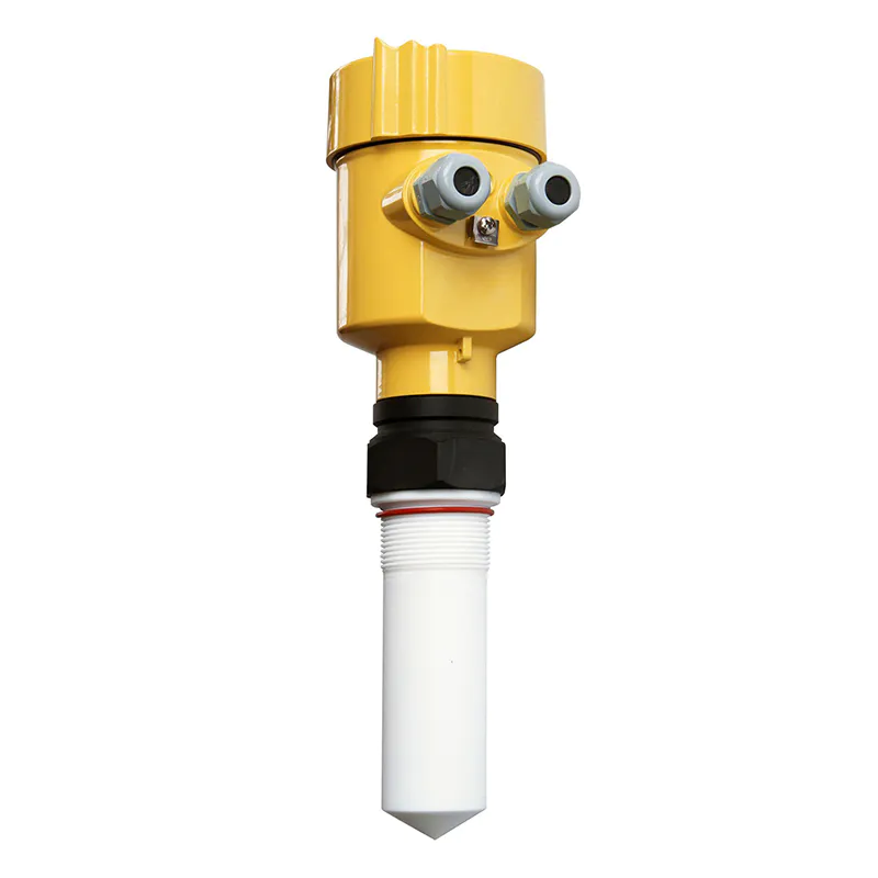
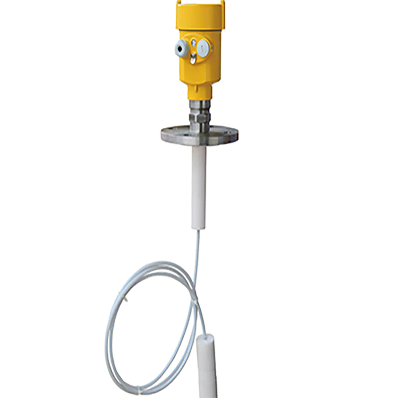
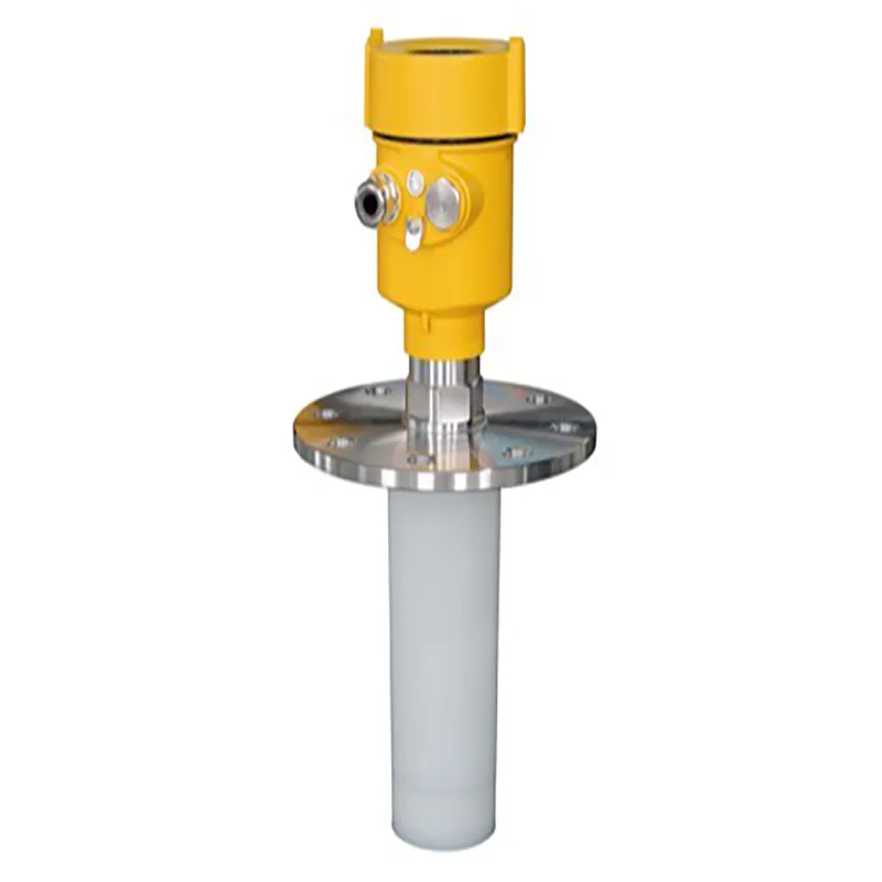
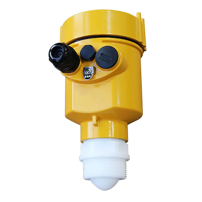
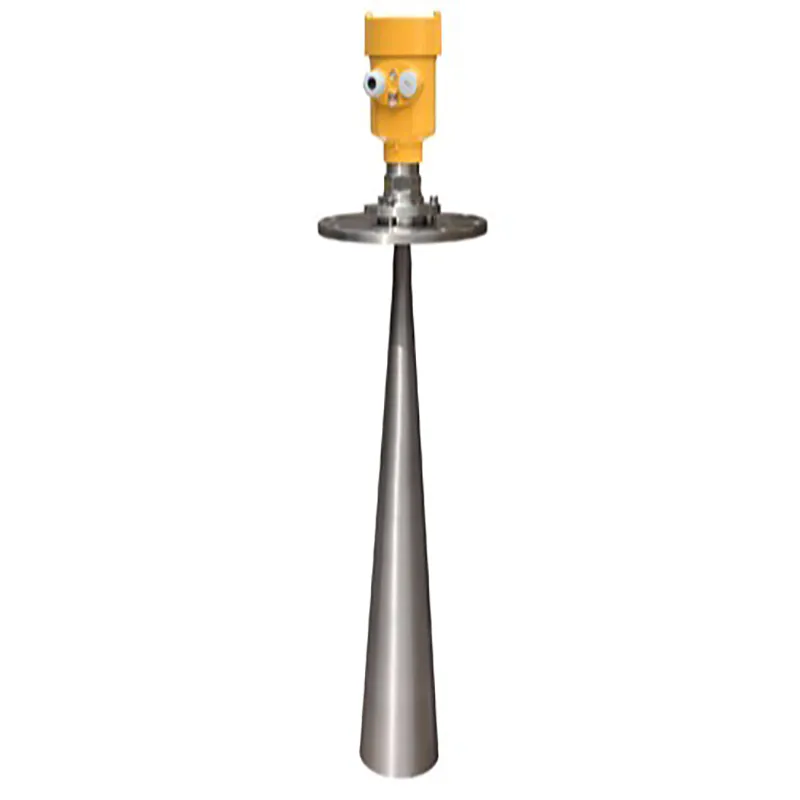
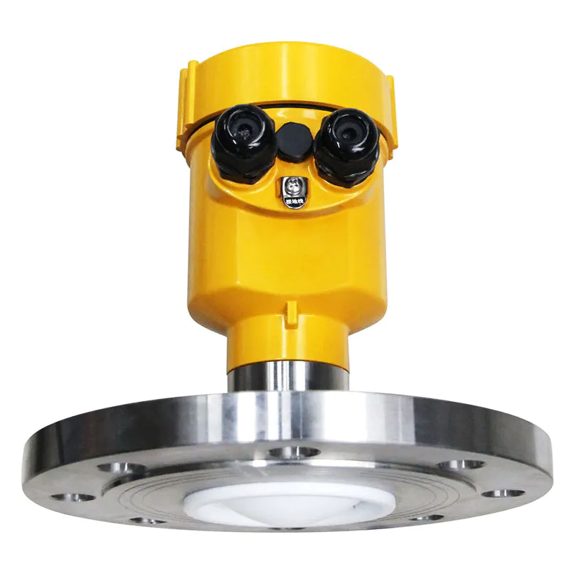
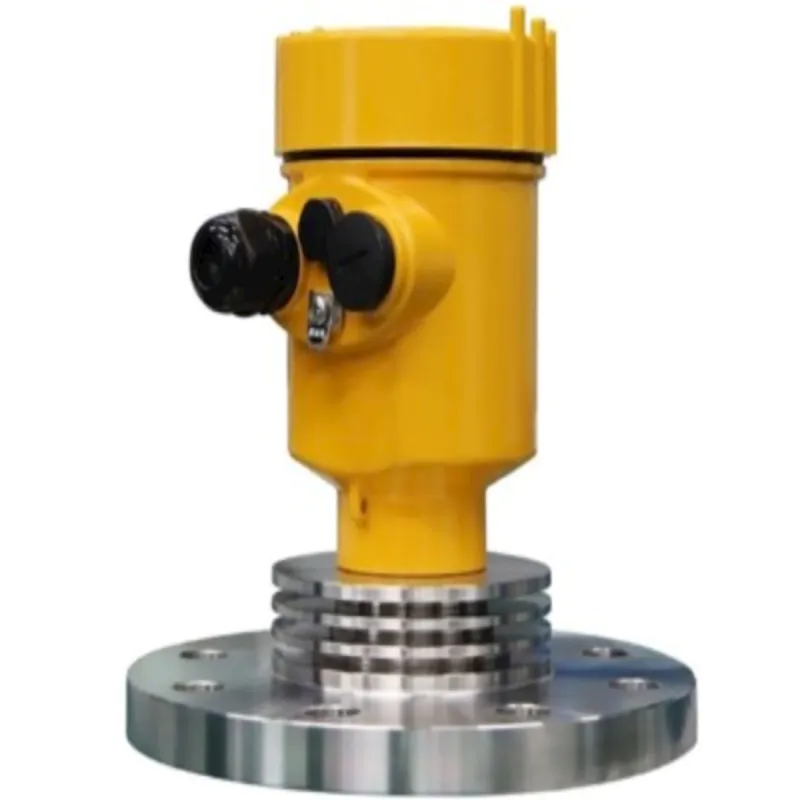
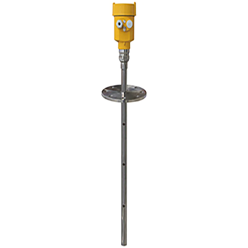
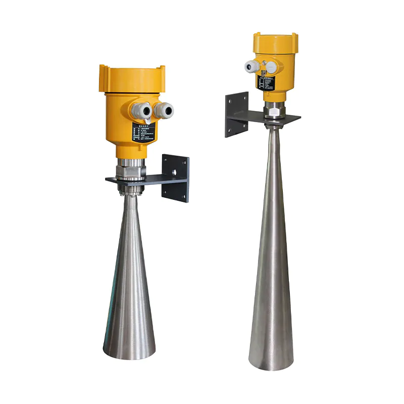
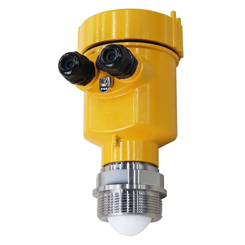
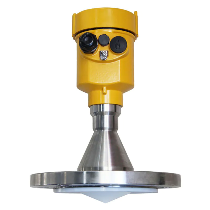
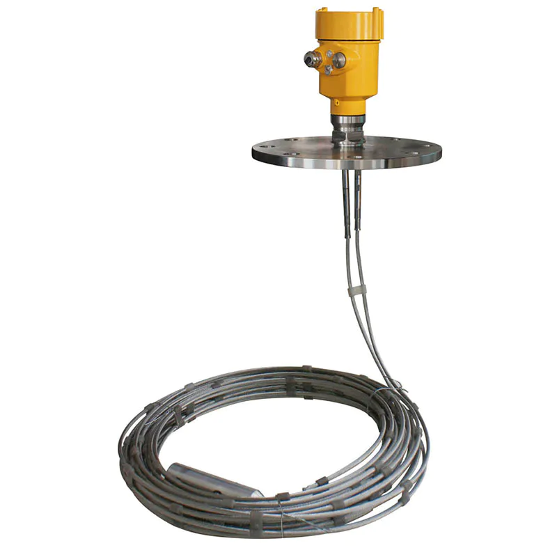
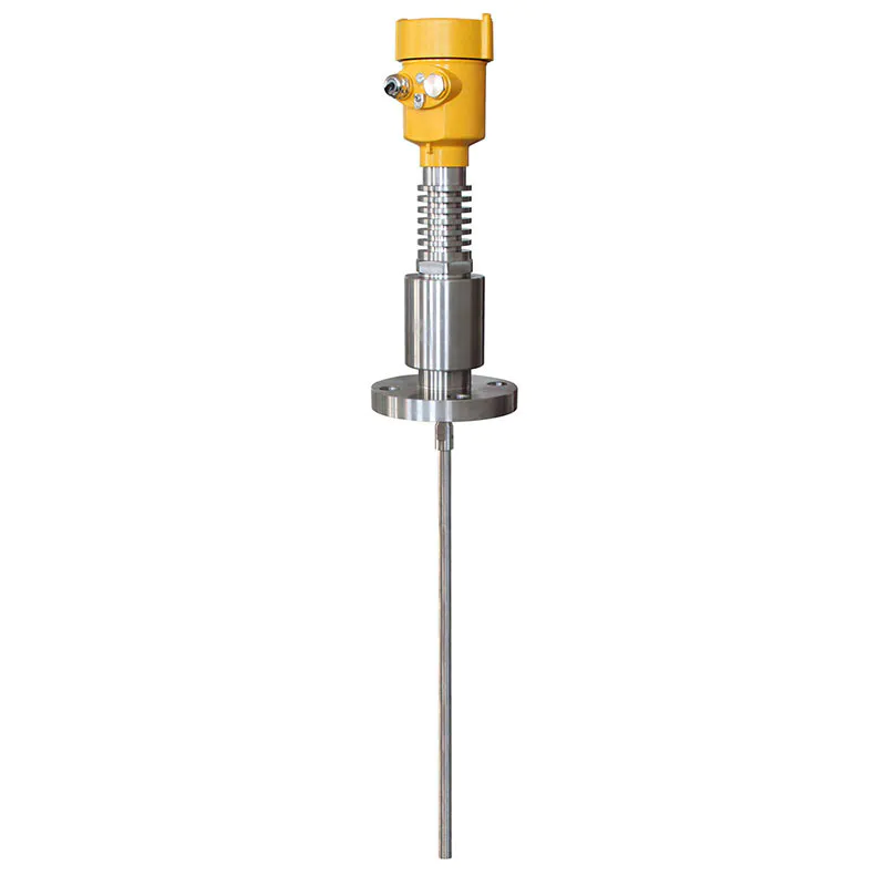
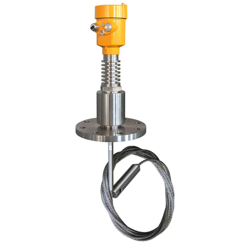
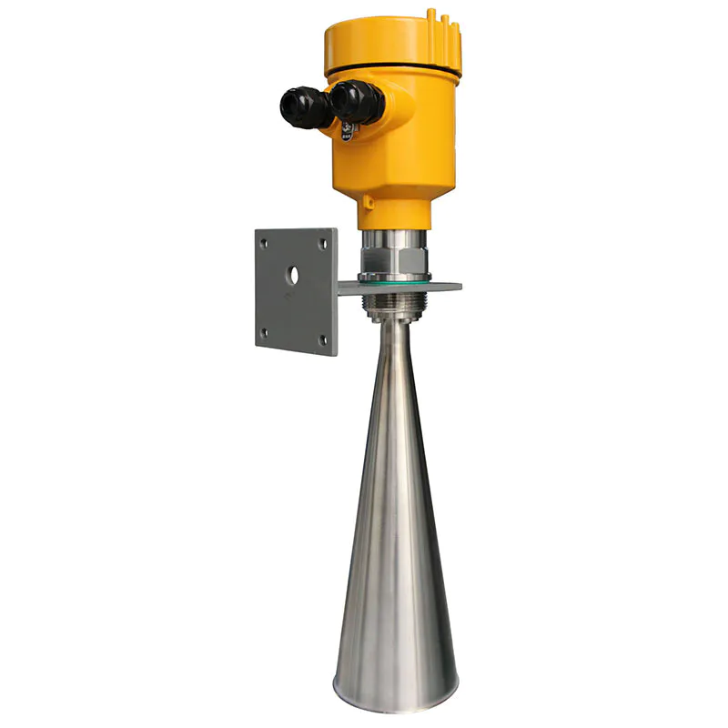
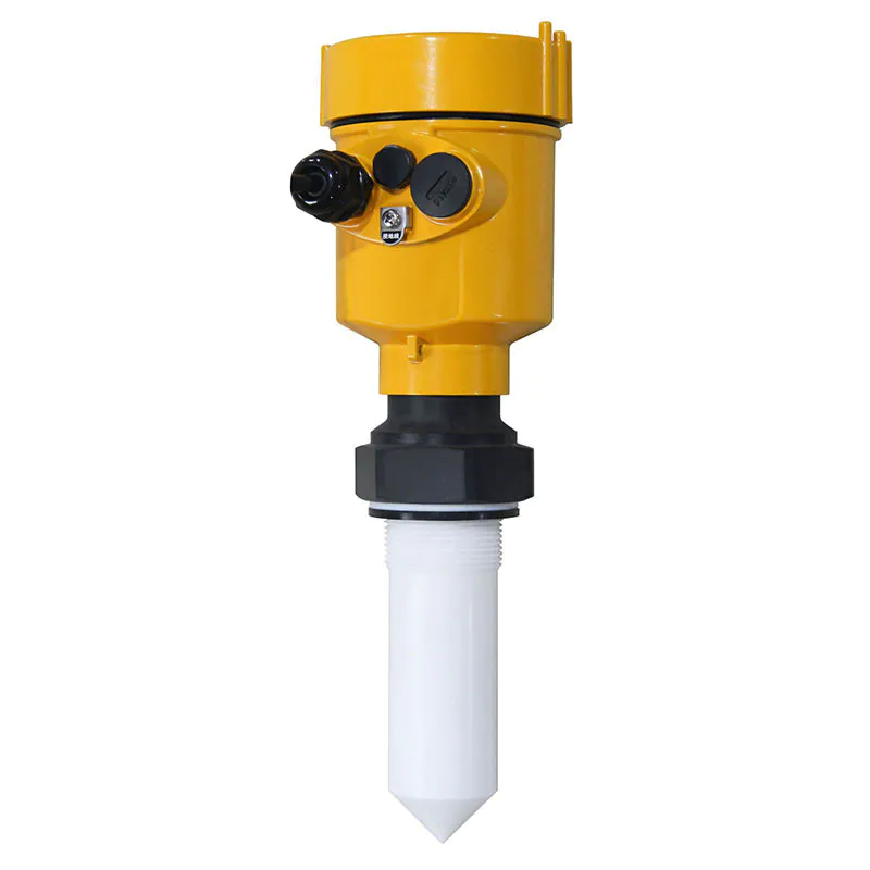
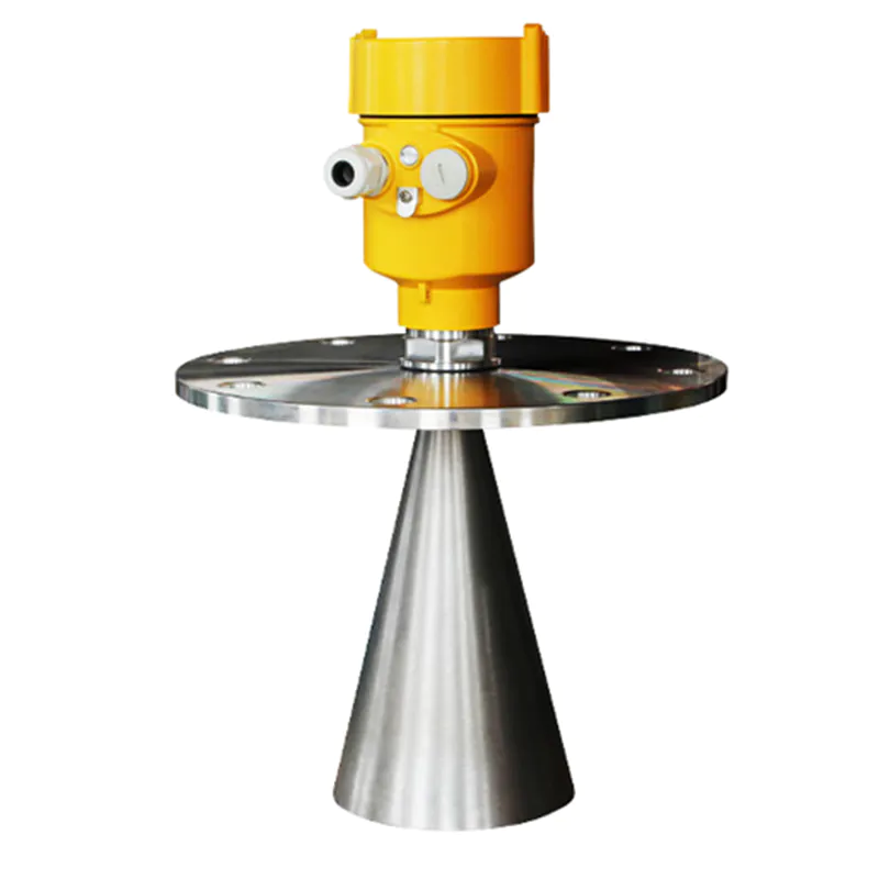
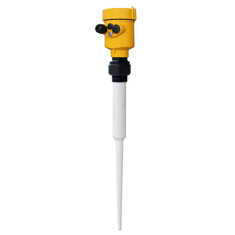
Radar Level Meter 80G FM Radar Type Level Measuring Instrument Kaidi KD-FMW21S FM
KDRD-FMW Series Sensor Is 80G FM Radar Type Level Measuring Instrument, Measuring Distance Up To 150 Meters
The antenna of the radar water gauge emits a very narrow microwave pulse. This pulse propagates in space at the speed of light and meets the surface of the measured medium. Part of its energy is reflected back and received by the same antenna. The time interval between the transmitted pulse and the received pulse is proportional to the distance from the antenna to the surface of the measured medium. Due to the extremely high propagation speed of electromagnetic waves, the time interval between the transmitted pulse and the received pulse is very small (nanosecond order) and it is difficult to confirm. The high-frequency radar water level gauge adopts a special demodulation technology, which can accurately identify the transmitted pulse and the received pulse. The distance between the antenna and the surface of the measured medium can be further calculated.
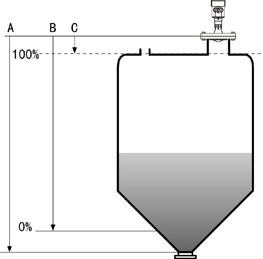
A range setting
B Low adjustment
C high adjustmen
The reference surface for measurement is: the bottom surface of the thread or the sealing surface of the flange
Note: When using radar water level timing, be sure to ensure that the highest water level cannot enter the measurement blind zone.
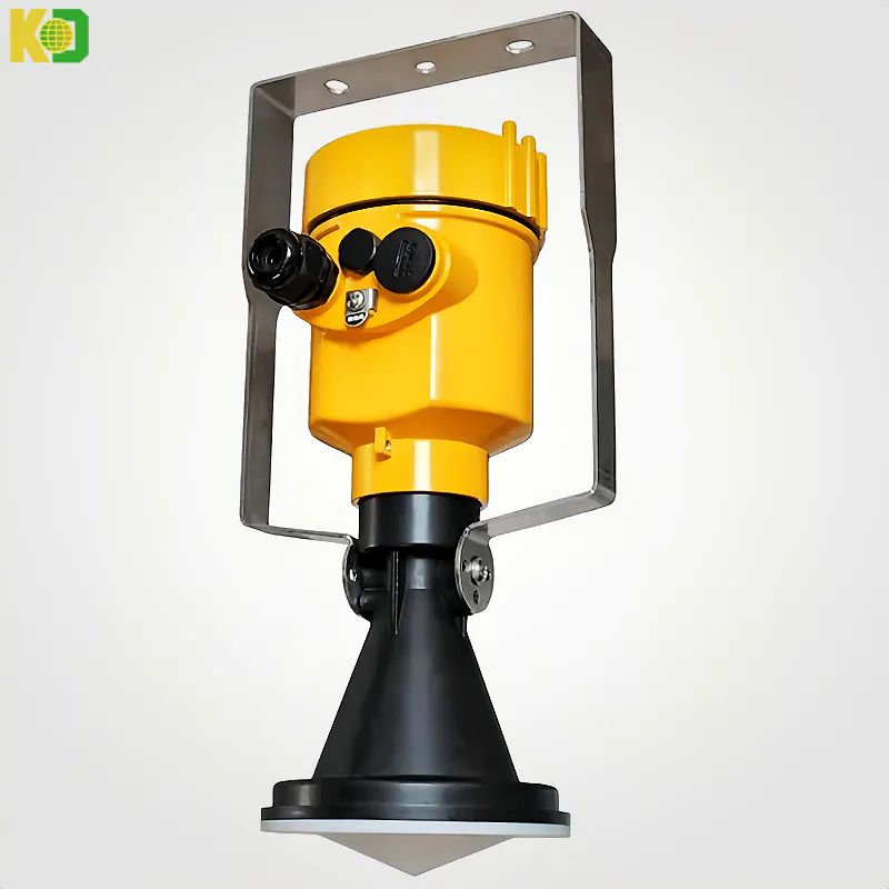
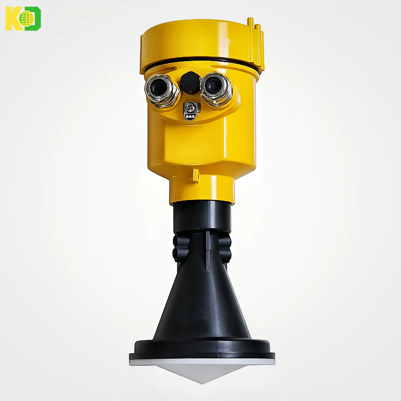
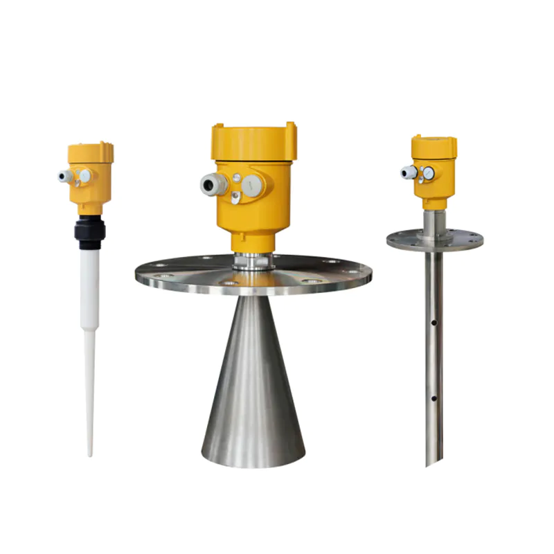
The radar water level gauge recommended by the industry uses a 26GHz transmission frequency, so it has:
▲Small beam angle, concentrated energy, stronger anti-interference ability, greatly improved measurement accuracy and reliability
▲The antenna size is small, easy to install and add dust cover and other antenna protection devices
▲Lighter about 1KG, easy to install
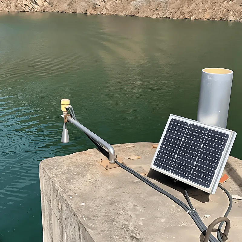
▲The measurement range is up to 30 meters, covering large-scale reservoirs and other water level measurement
▲Multiple output circuit interfaces to cooperate with the acquisition system
▲Using pulse working mode, the transmitting power of the radar water level gauge is extremely low, and there is no harm to the human body and the environment
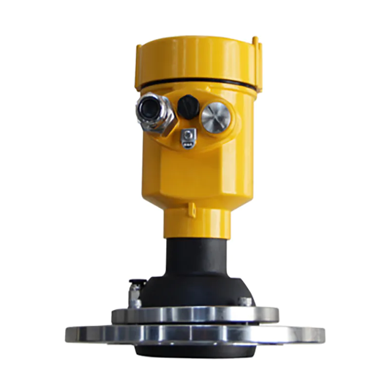
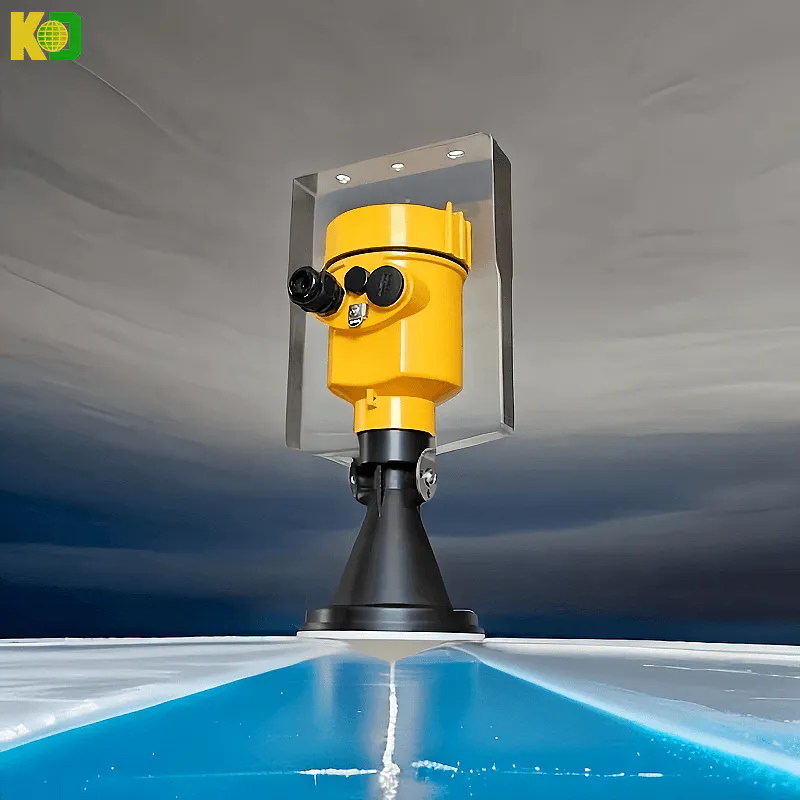
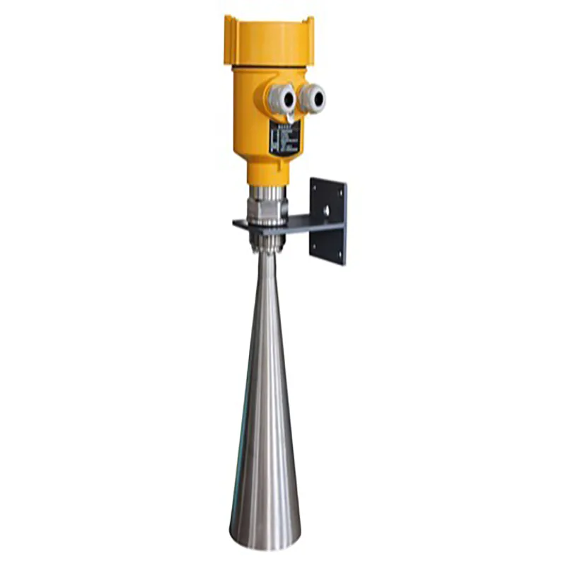
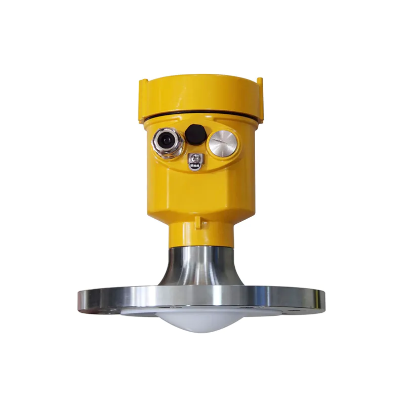
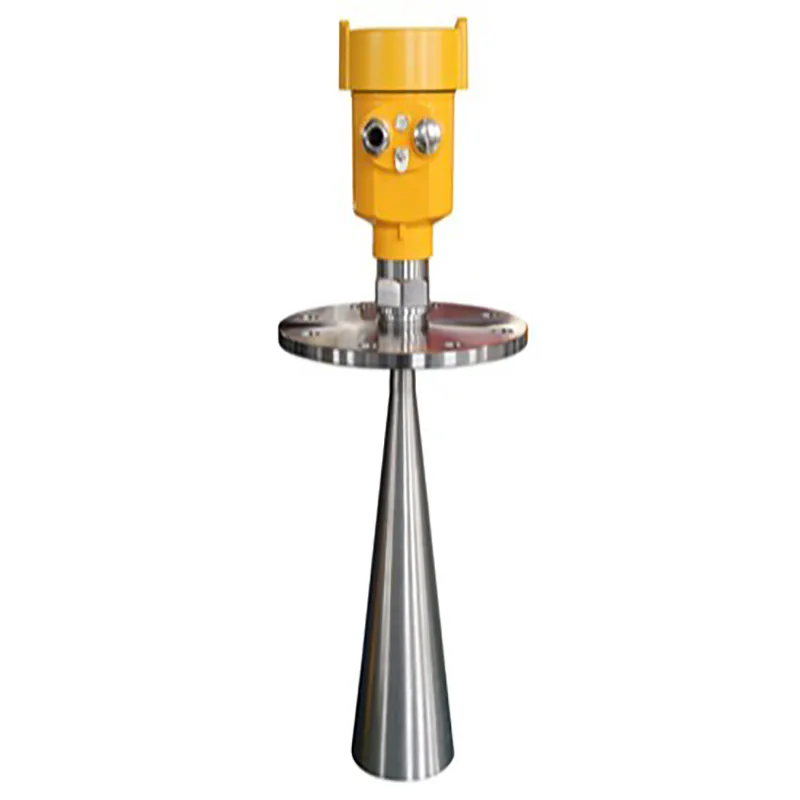
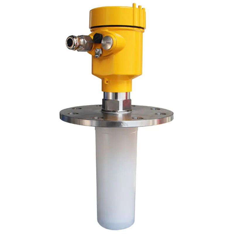
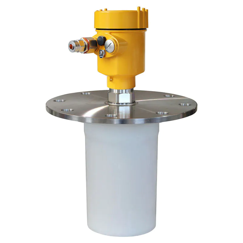
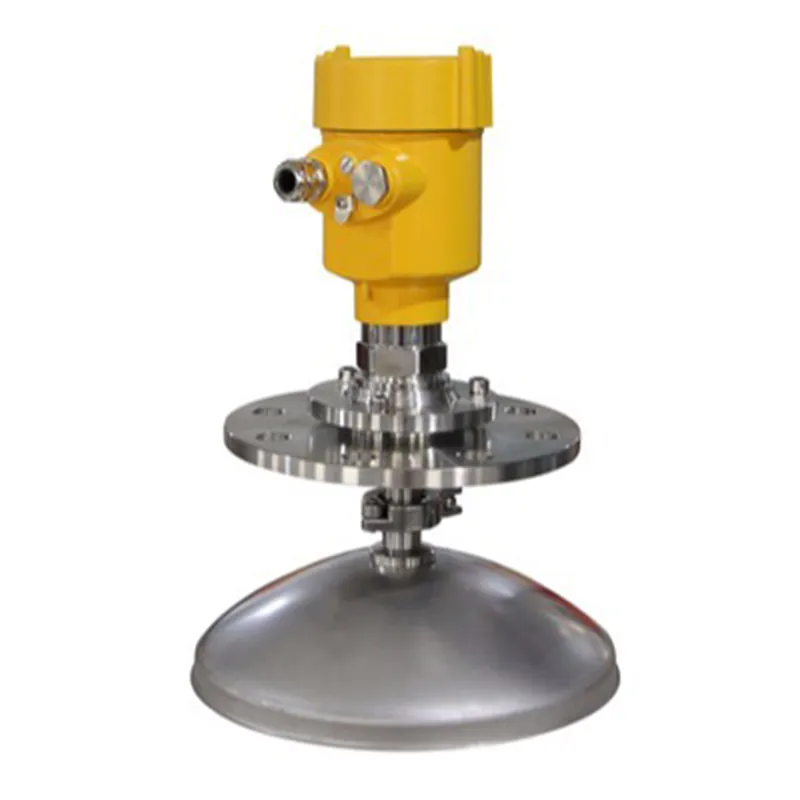
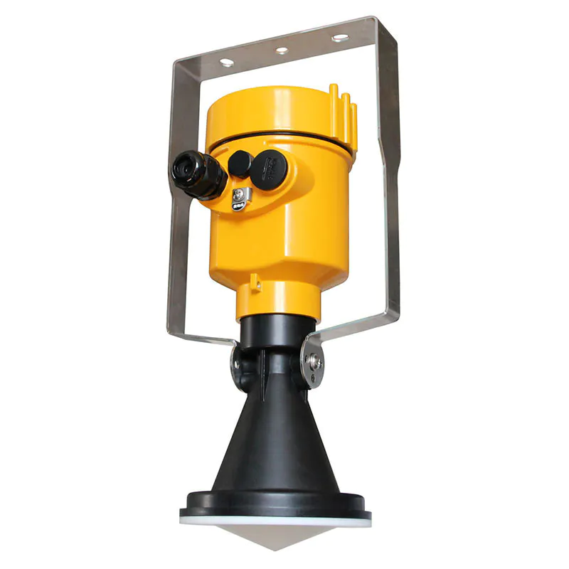
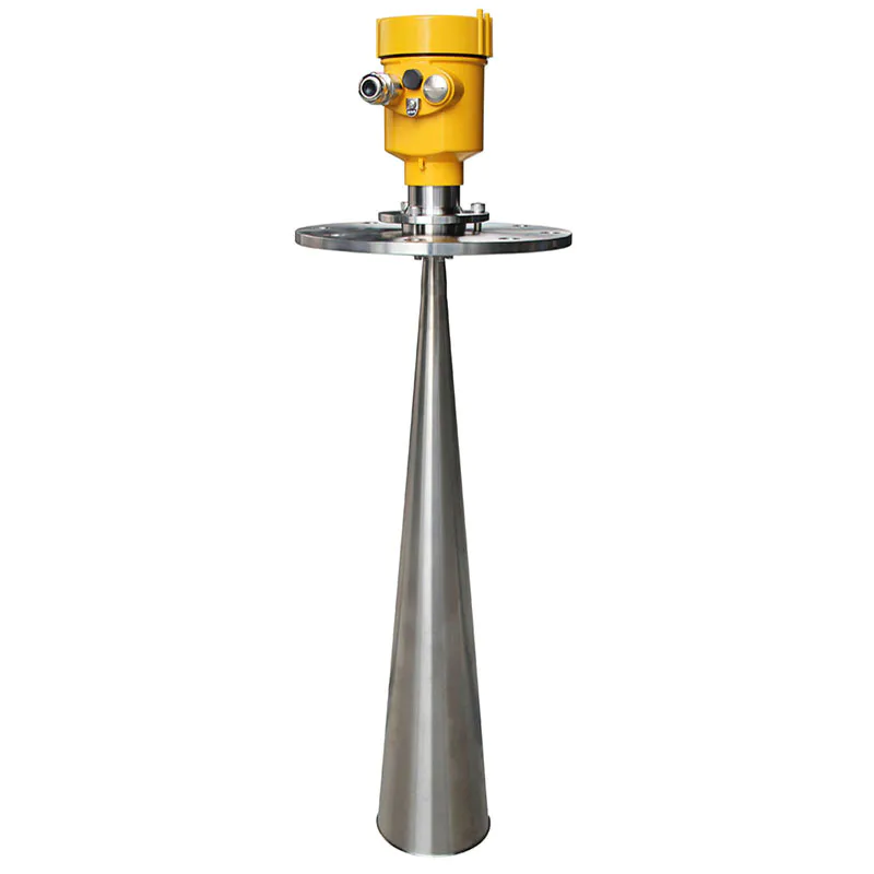
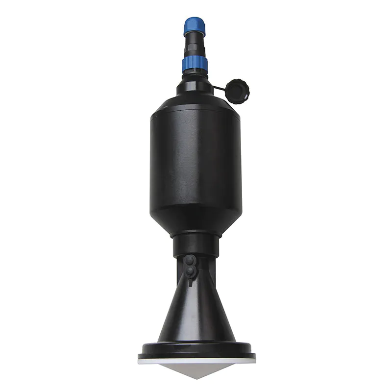
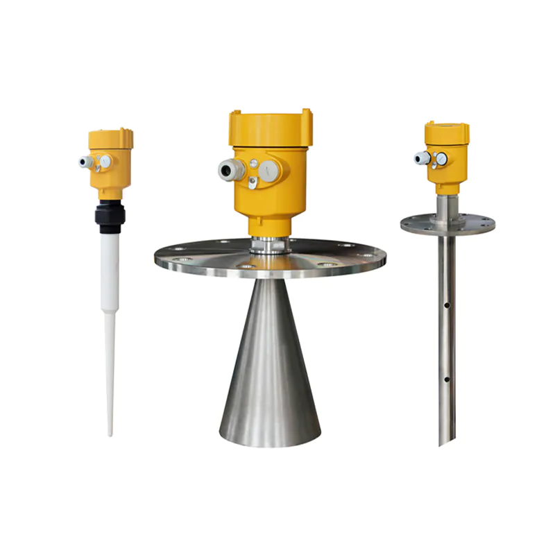
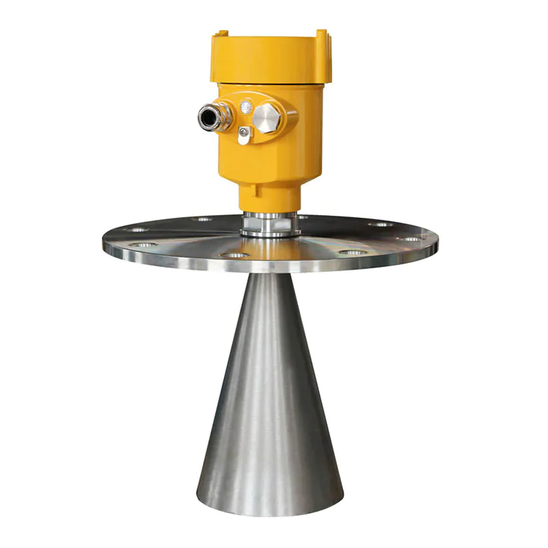
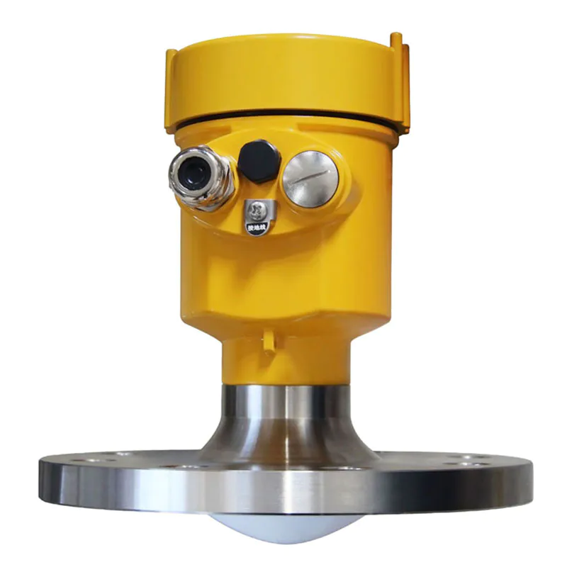
●908S
Application: rivers, lakes, shallows
Measuring range: 0~30 meters
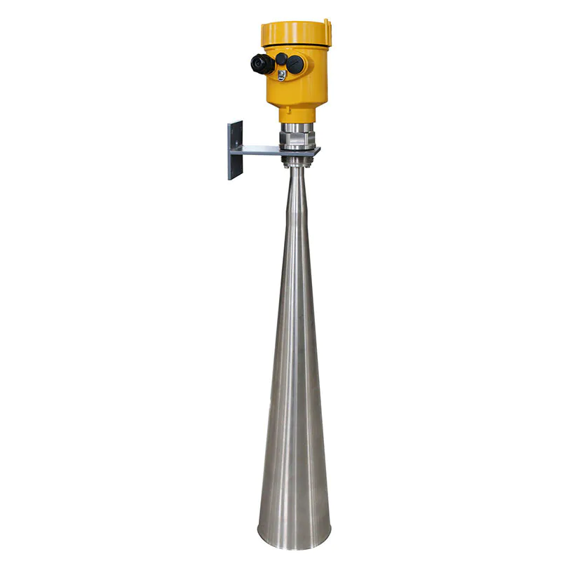
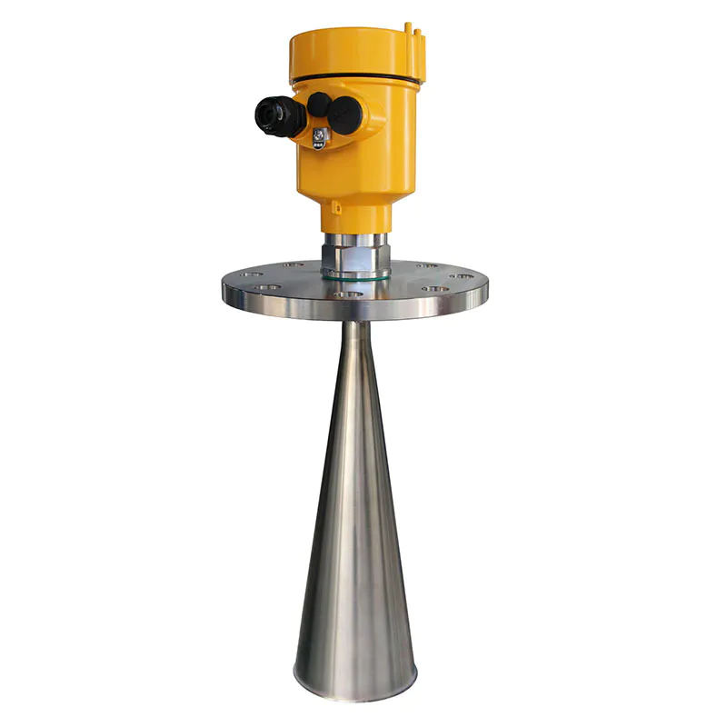
Process connection: gantry frame,Locking flange from DN 80/ 3"
Process temperature: -40~80℃
Process pressure: (-0.1~0.3) MPa
Precision: ±3mm
Frequency: 26GHz
Protection grade: IP67 / IP65
Power supply: DC (6-24V) / four wires DC 24V / two wires
Signal output: Modbus-RS485 protocol (6~24V DC) 4~20mA/Hart two wires (24V DC)
On-site display: optional
Shell: cast aluminum / plastic
l Preparation before installation:
Ø Please pay attention to the following matters, to ensure that the instrument can be installed correctly:
Ø Please reserve enough space for installation.
Ø Please avoid installing occasions strong vibration.
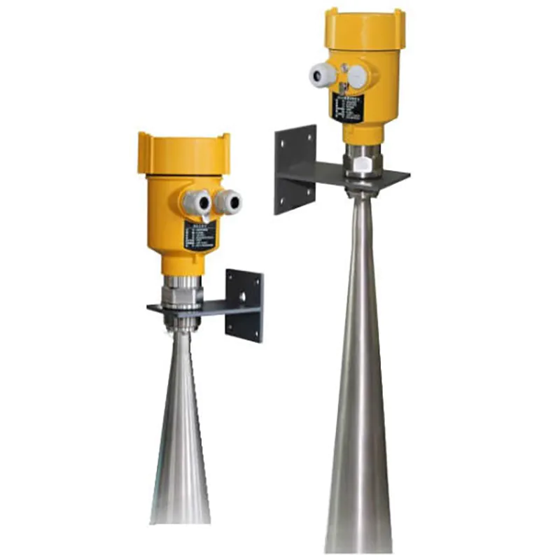
l 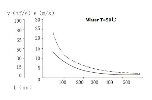 Illustration and installation position
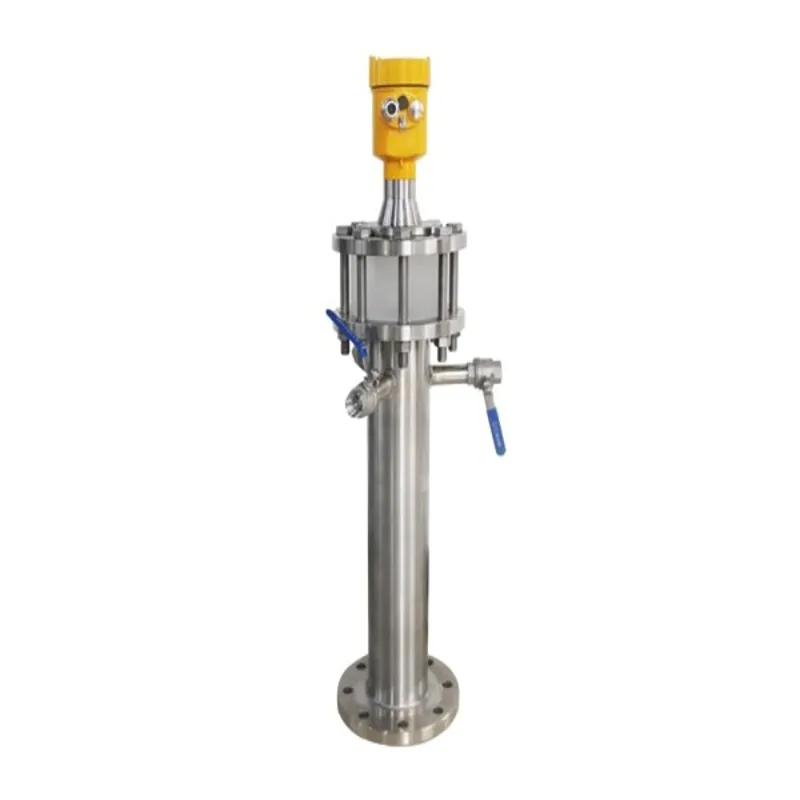
Schematic diagram of radar and stent
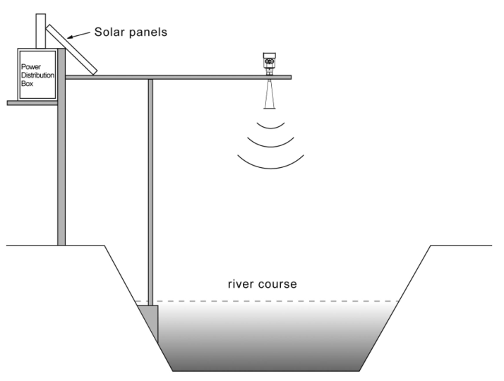
Note: Radar antenna microwave pulse, have a certain emission angle. From the lower end of the antenna to be measured between the surface of the medium, and a transmitter shall be no obstruction in the region of the microwave beam radiation. Therefore, the installation should be avoided as far as possible shelter facilities, shall be carried out "false echo study" when necessary. Also note that when installing devices: the highest level measured shall enter blind; instrument must be connected to the earth, increasing the lightning protection measures; outdoor shade should be taken, rain measures.
Power Supply voltage
RS485/Modbus power supply and Modbus signal lines separated respectively using a shielded cable, the power supply voltage range of see technical data.
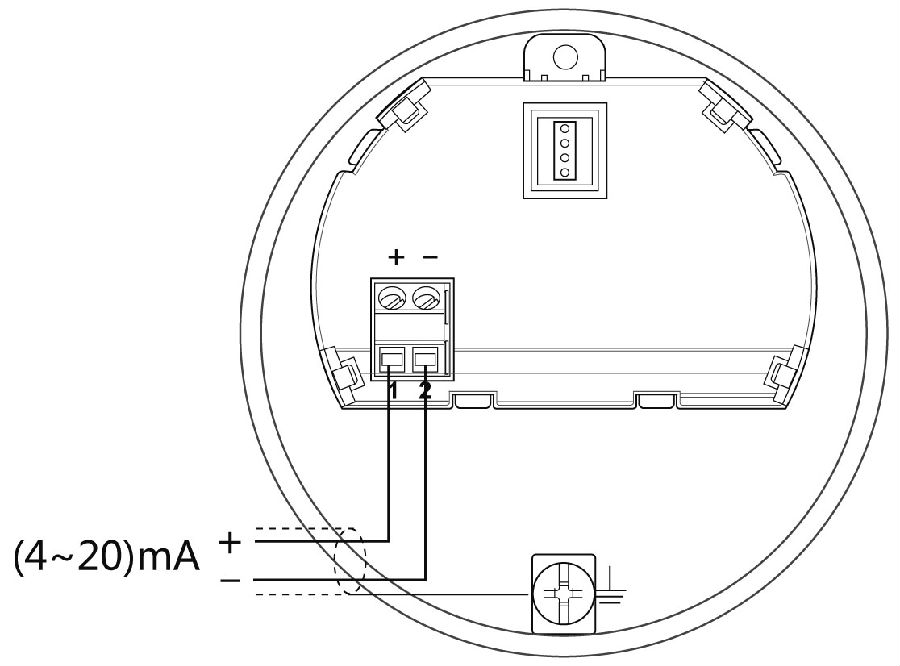
(4~20)mA/HART (Two wire system) The power supply and the output current signal sharing a two core shield cable. The supply voltage range see technical data. For intrinsically safe type must be a safety barrier between the power supply and the instrument.
Connection mode
l The RS485/Modbus wiring diagram as follows:
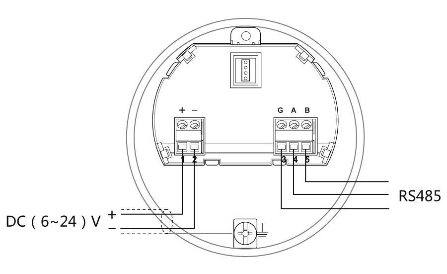
l 24V two wire wiring diagram as follows:
Safety instructions
Please make sure that the sealing head is not damaged.
Please make sure that the cable is not damaged.
Please make sure that the cable for use with electrical connection specification.
Cable into the electrical interface before its curved downward, ensure that the water will not flow into the shell, see the①
Tighten the cable seal head, see the②
Please electrical interface will not use blind plug tight, see the③
Protection grade
This instrument meets the protection grade IP66/67 requirements, please ensure the waterproof cable sealing head.
How to install to meet the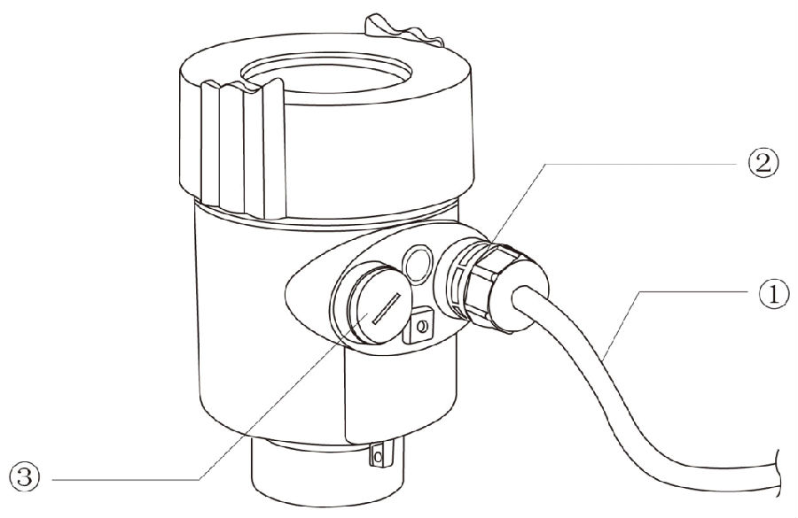 requirements of IP67:
Please make sure that the sealing head is not damaged.
Please make sure that the cable is not damaged.
Please make sure that the cable for use with electrical connection specification.
Cable into the electrical interface before its curved downward, ensure that the water will not flow into the shell, see the①
Tighten the cable seal head, see the②
Please electrical interface will not use blind plug tight, see the③
l There are three kinds of debugging method:
1) Display / Keyboard
2) Host debugging
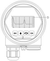
l Display / Keyboard:
Please debug the instrumentation by four buttons on the display screen. There are three debug menu languages optional. After debugging is generally used only for display, through the glass window can read measured value very clearly.
Display / Keyboard
① Liquid crystal display(LCD)
② The key
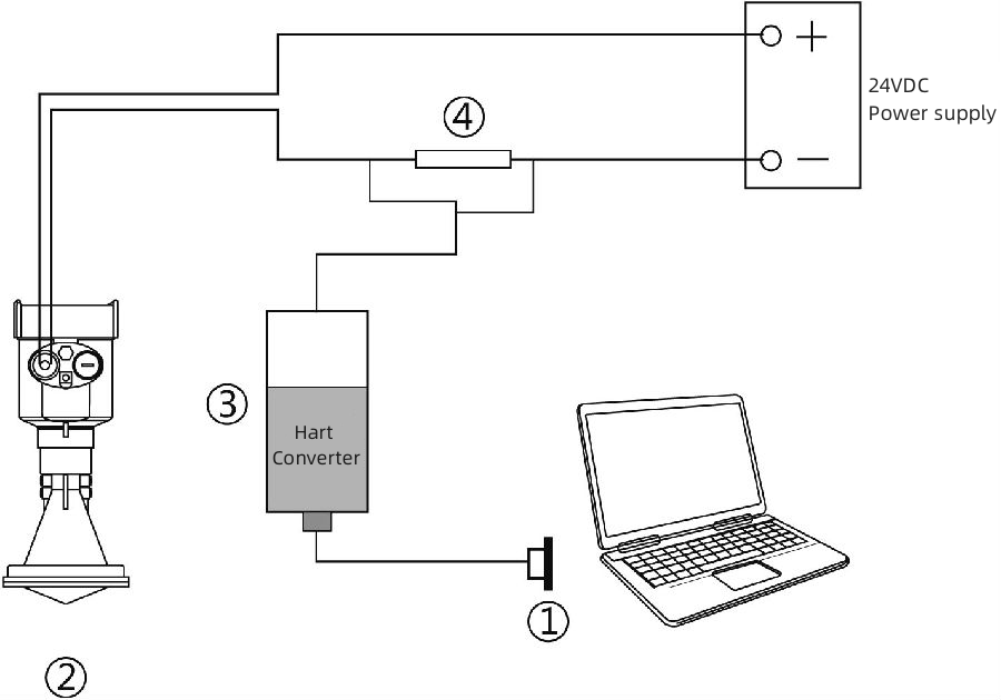
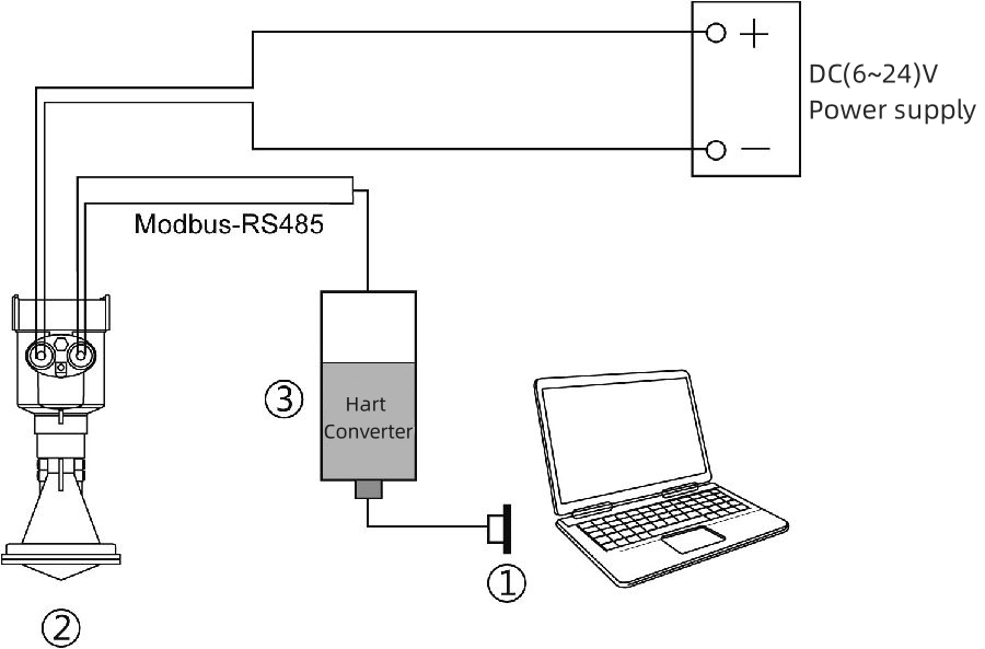
l PC debugging:
Connected to PC by HART
① RS232 interface or USB interface
② Radar level meter
③ HART adapter
④ 250 Ω resistor
●Connect to the host computer through the RS485 converter
① RS232 interface/or USB interface
② Radar water level gauge
③ RS485 converter
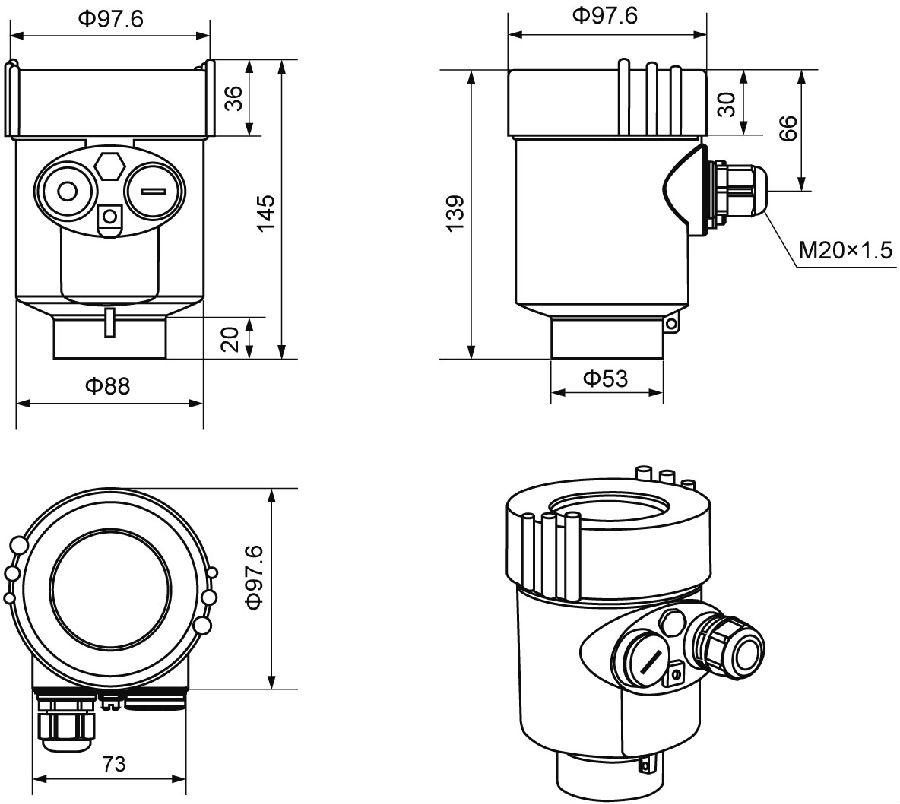
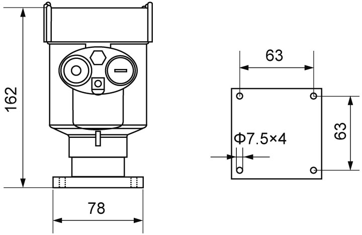
●Case size:
➪Cast aluminum case
➪Plastic case
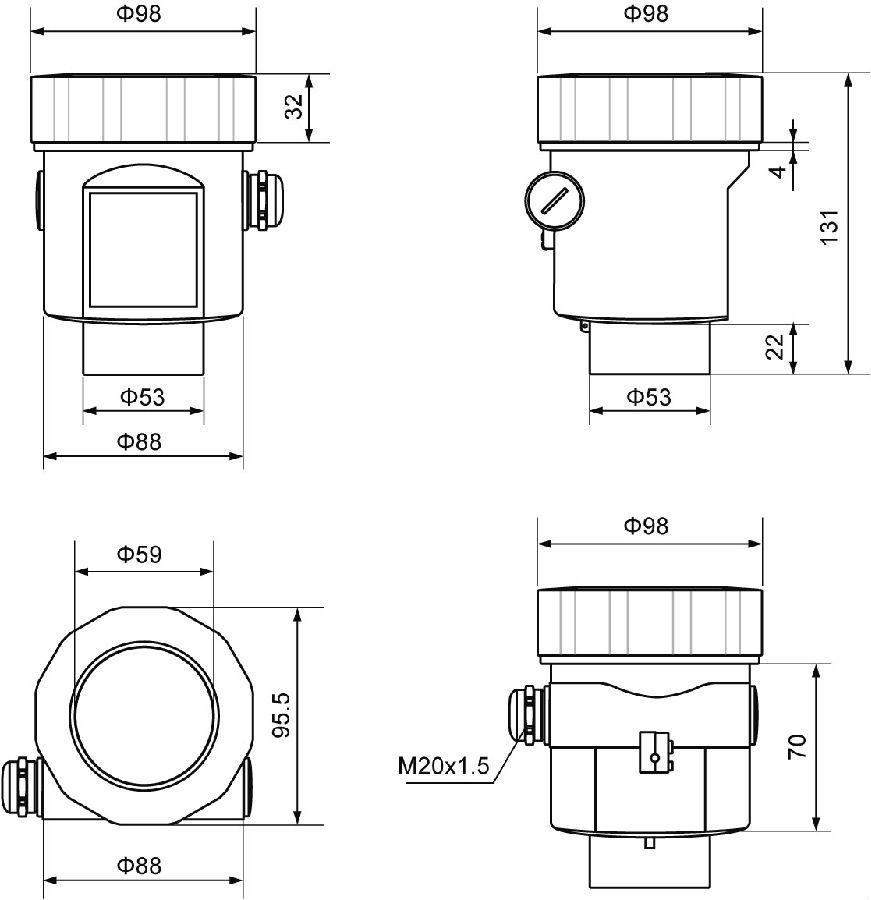
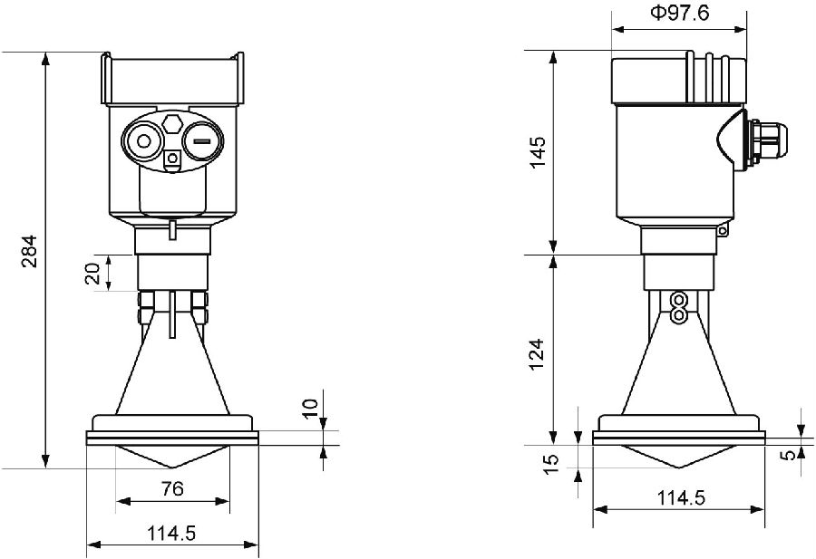
● Product Size
● If there is a split display, the size of the water conservancy split display:
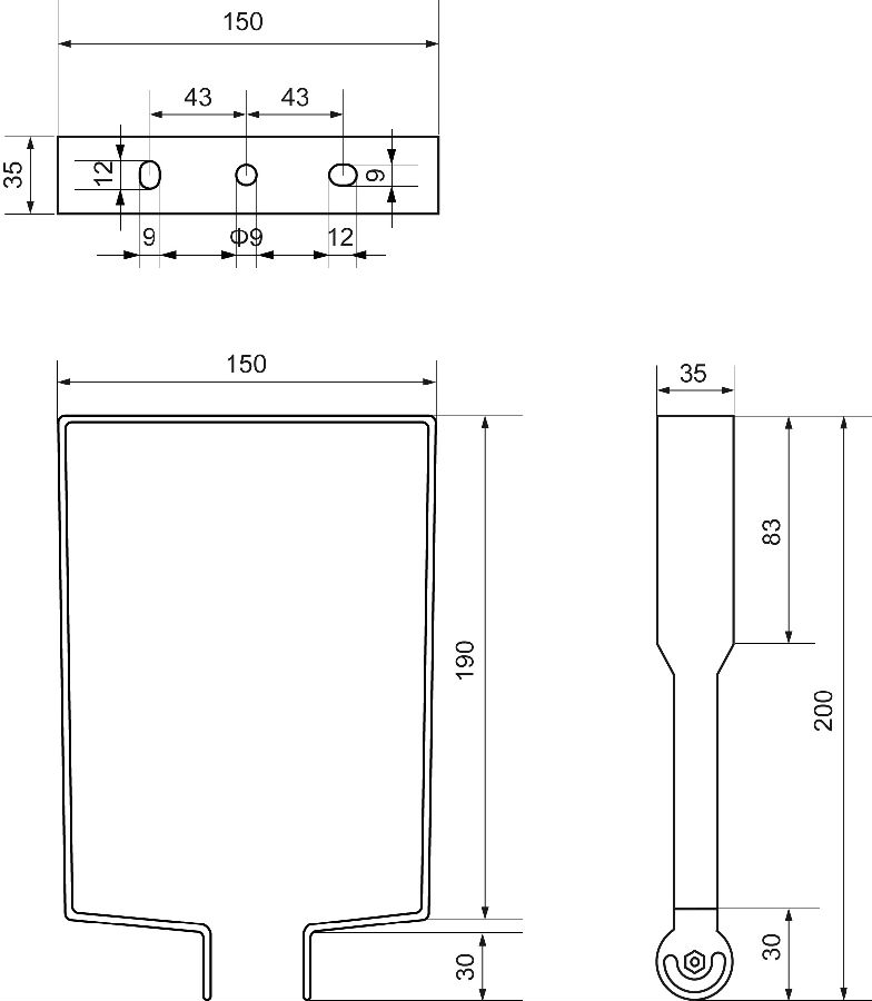
● Gantry frame size
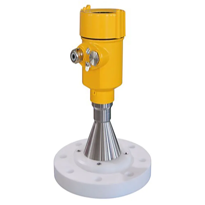
Shell/material cast aluminum, plastic, stainless steel
Seal between Shell and Shell cover Silicone rubberShell window polycarbonate
Ground terminal stainless steel
The power supply voltage
Four-wire system (6~24) V DC / Modbus-RS485 / power consumption 90mW
Two-wire system DC 24V / 4~20mA / power consumption 0.75W
Allowable ripple- <100Hz Uss<lV
-(100~100K) Hz Uss<l0mV
The cable parameters
Cable entrance / plug 1 M20xl.5 cable entrance
erminal Conductor cross section 1.0mm²
Output parameters
The output signal Modbus-RS485 / 4~20mA
Communication protocol Modbus / Hart
Resolution 1.6μA
Fault signal Constant current output;
20. 5mA
22mA
3.9mA
The integral time (0 ~ 36) s, adjustable
Blind area the ends of the antenna
The maximum distance measurement 30 meters
Microwave frequency 26GHz
Communication interface HART communication protocol
The measurement interval about 1 second (depending on the parameter settings)
Adjust the time about 1 second (depending on the parameter settings)
Display resolution 1 mm
Working storage and transportation temperature (-40~80) ℃
Process temperature (the temperature of the antenna part) (-40~80)℃
Pressure Max. 4MPa
Seismic Mechanical vibration l0m/s², (10 ~ 150) Hz
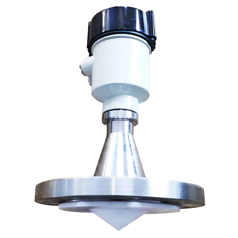
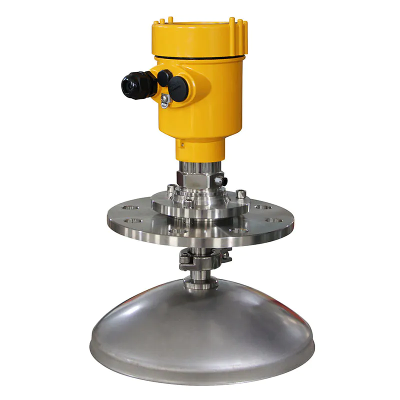
The launch angle depends on the antenna size
-¢76mm 12°
Accuracy see the figure below
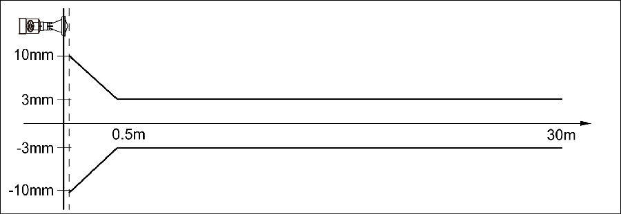
l 908S
![]() License
License
P Standard (Non-explosion-proof)
![]() Process Connection / Material
Process Connection / Material
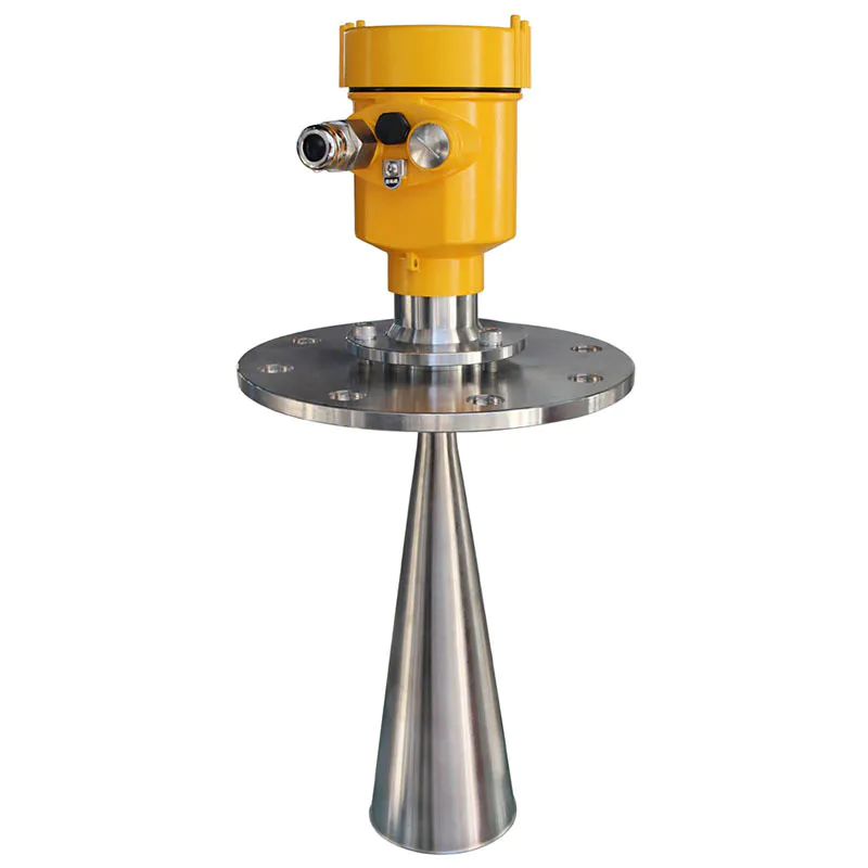
N gantry frame
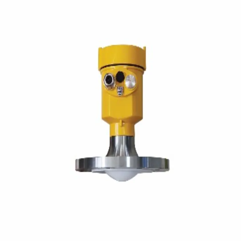
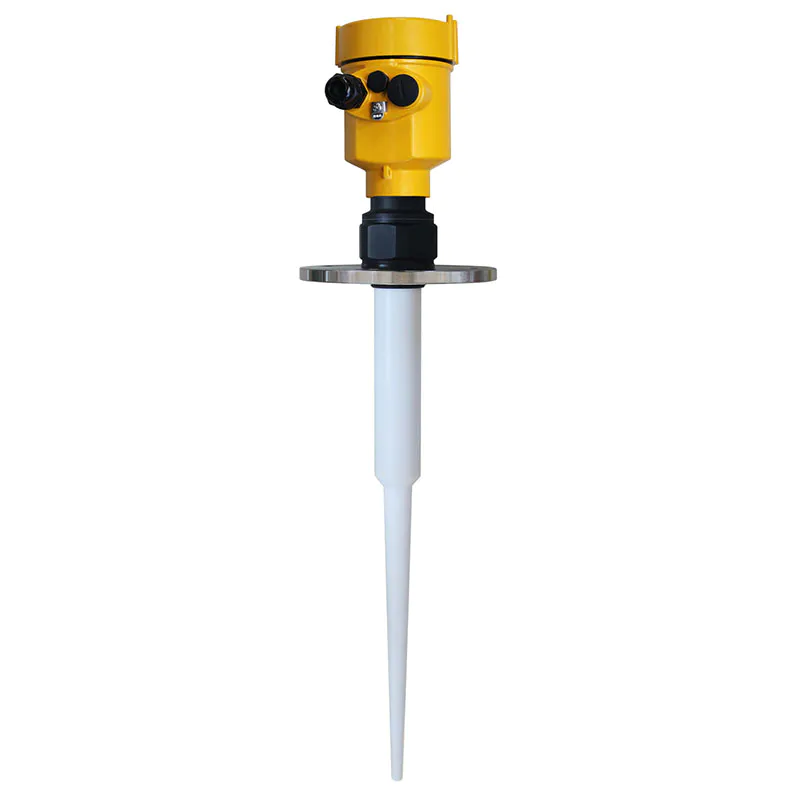
M PP flange installation
Y special customization
![]() Seal Up / Process Temperature
Seal Up / Process Temperature
V Viton / (-40~80) ℃
![]() The Electronic Unit
The Electronic Unit
V RS485-Modbus / four-wire system
W (4~20) mA / 24V DC two-wire system
![]() Outer Covering / Protection Grade
Outer Covering / Protection Grade
L aluminum/IP67
G plastic /IP65
![]() Cable Line
Cable Line
M M 20x1.5
N ½″ NPT
![]() Field Display/The Programmer
Field Display/The Programmer
A With
X Without
![]()
We are here to help you! If you close the chatbox, you will automatically receive a response from us via email. Please be sure to leave your contact details so that we can better assist


![kaidi KD-906 26G Radar Level Meter [Anti-corrosion] High Temperature Intelligent](https://img80003270.weyesimg.com/uploads/kaidi86.com/images/16760218661446.jpg?imageView2/2/w/1920/q/80/format/webp)


![kaidi KD-802 6G Radar Level Meter [Anti-corrosion Type]](https://img80003270.weyesimg.com/uploads/kaidi86.com/images/15936739299092.jpg?imageView2/2/w/1920/q/80/format/webp)
![kaidi KD-FMF15 FM radar level meter [chemical and electric power industry]](https://img80003270.weyesimg.com/uploads/kaidi86.com/images/15936722293812.jpg?imageView2/2/w/1920/q/80/format/webp)