Application :
The Measurement Principle
Antenna system to launch and microwave receiving energy is very low, very short pulse. Radar waves travel with the speed of light. The running time can be through the electronic components are converted into a signal. Measurement of this special time extension method can realize stable, accurate in a very short period of time.
Even if the condition is very complex, the presence of false echo, with the latest micro-processing technology and debugging software also can analyze the level echo accurately.
Suitable for Medium: | Liquid, solid powder |
| Application: | Liquid and solid powder measure, complicated process conditions |
| Explosion-proof Grade: | Exia IIC T6 Ga/Exd IIC T6 Gb |
| Measuring Range: | 30m、20m、6m |
| Frequency: | 500MHz-1.8GHz |
| Antenna: | Single cable or single rod antenna |
| Accuracy: | ±10mm |
| Process Temperature: | (-40~250)℃ |
| Process Pressure: | (-0.1~4)Mpa |
| The signal Output: | (4 ~ 20) mA/HART |
| The Scene Display: | Four LCD /Can be programmed |
| Power Source: | Two-wire (DC24V) 、Four-wire (DC24V/AC220V) |
| Shell: | Aluminum /Plastic / Stainless steel |
| Connection: | Flange (optional) / Thread |
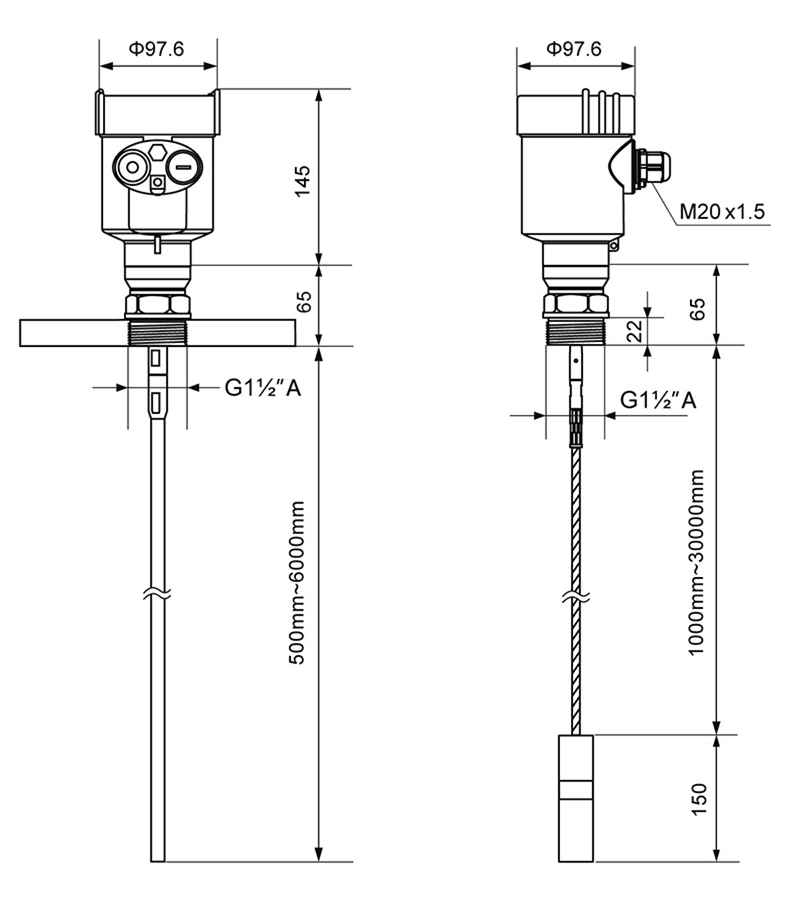
1. Dimensions of Instruments
l Structure size (unit: mm)
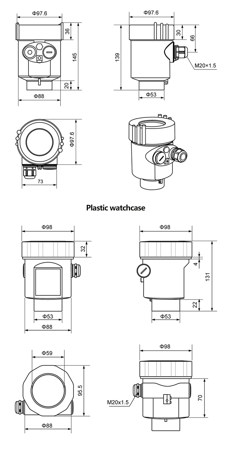
l Cast aluminum case (unit: mm)
2. The Electrical Connection
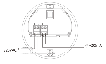
l The power supply voltage:
| (4~20)mA/HART (Two wire system) | Power supply and current signal are carried by the same two-wire connection cable. See the Technical Specifications of this guide for detailed requirement on power supply. A safety barrier should be placed between power supply and instrument for intrinsically safe version. |
| (4~20)mA/HART(Four wire system) | Power supply and current signal are carried by two 2-wire connection cables respectively. See the Technical Specifications of this guide for detailed requirement on power supply. Earth-connected current output can be used for standard version of level instruments, while the explosion proof version must be operated with a floating current output. Both instruments and earth terminals should be connected with ground firmly and securely. Normally you can either choose to connect with the earth terminal on vessel or adjacent ground in case of plastic vessels. |
l Connection mode:
Ø 24V two wire wiring diagram as follows:
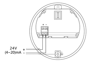
Ø 220V four wire connection is as below:
l Explosion Proof Connection
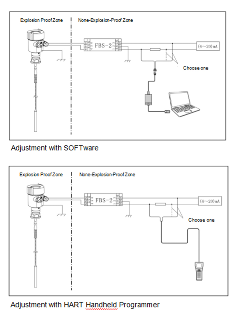
The intrinsic safety version sensors (Exia IIc T6) use Alu-die casting housing and filling Silicone rubber sealants internal structure aimed to prevent sparks resulted from circuit failure from leaking out. It is applicable for the continuous level measurement of flammable medium under Exia IIc T6.
A safety barrier FBS-2 must be used together with the intrinsic safety instrument. It is an associated device to this product for the power supply of this product. The main specification is intrinsic safety: Exia IIC, voltage of power supply: 24V DC±5%, short-circuit current: 135mA, operating current: 4...20mA.
All cables must be shielded. The max length is 500m for the cable from the barrier to the sensor. Stray capacitor≤0.1μF/Km, stray inductance 1mH/Km. Instrument must be connected to the ground potential. Any unapproved associated device is not allowed to be used.
l Safety instructions:
Ø Please observe the local electrical code requirements!
Ø Please comply with local requirements for personnel health and safety regulations.
All electrical components of instrument operation must be completed by the formal training of professionals.
Ø Please check the instrument nameplate to provide product specifications meet your requirements. Please make sure that the power supply voltage and instrument nameplate on the requirements.
l Protection Grade:
The instrument fully meet the requirements of protection class IP66/67, make sure the cable head waterproof seal. As shown below:
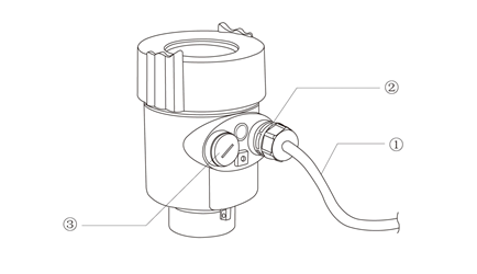
² How to ensure that the installation meets IP67 requirements:
² Make sure that the sealing head is not damaged.
² Make sure that the cable is not damaged.
² Make sure the cable is used in line with the electrical connection specifications.
² Before entering the electrical interface, the cable is bent down wardly, to ensure that water does not flow into the casing, see ①
² Please tighten the cable sealing head, see ②
² Keep electrical interface with blind unused block after block tight, see ③
3. Adjustment Instructions
l Adjustment Methods:
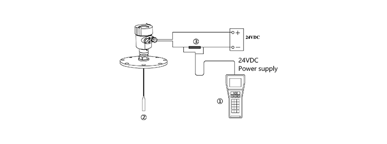
① Display/adjustment module ViewPoint)
② An adjustment software
③ HART handheld programmer
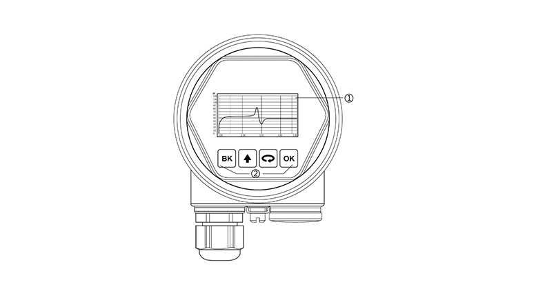
l Display / Adjustment Module
View Point is a display debugging tool that can be plugged in. The adjustment can be done through operating with four buttons on View Point. Optional menu operation languages are available for selection. View Point is only used for display after adjustment in that the measurement results can be seen clearly through the glass window.
l PC debugging
Connect with another unit through HART
1) RS232 Connect Cable /USB port
3 )HATR port adapter used on COMWAY convertor
4)250 ohm Resistance

l HART Handheld Programmer
4. Technical Specification
General Parameters
| Probe Material: | |
| Rod | Stainless steel 316L/PTFE |
| Cable | Stainless steel 316L/PTFE |
| Coax | Stainless steel 316L/PTFE |
| Seal | Viton fluororubber , Kalrez Fluorinated rubber |
| Process Connection | Stainless steel 316L |
| Shell | Stainless Steel 316L, Plastic,Aluminum Alu-die casting, Powder Coated |
| Seal ring between the shell and the shell | Silicone Rubber |
| View Point Window | Polycarbonate |
| Ground Terminal | Stainless Steel 316L |
| Power (2-Wire) | |
| Standard Version | (16~26)V DC |
| Intrinsic Safe Version | (21.6~26.4)V DC |
| Power Consumption | max. 22.5mA |
| Flameproof Type | |
| (22.8 ~ 26.4) V DC 2-wire system | |
| (198 ~242)V AC 4-wire system / 110V AC 4-wire system | |
| Power Consumption max. 1VA,1W | |
| Parameters on Cable | |
| Cable Entry/Plug | One cable entry of M20xl.5 (cable diameter of 5~9mm) One blind stopper M20xl.5 |
| Spring Connection Terminal | Applicable for cables with cross section of 2.5mm |
| Output | |
| Output Signal | (4~20)mA/HART |
| Resolution | 1.6μA |
| Failure mode | 20.5mA;22mA;3.9mA, hold |
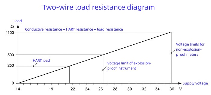
| 2-wire load resistance | See the diagram below |
| 4-wire load resistance | Max.500 ohm |
| Integration Time | ( 0~36)sec, adjustable |
l Technical data
| Technical data | |
| Max Measurement Distance | |
| 701 | 30m/6m(Cable /Rod) |
| 702 | 20m/6m(Cable /Rod) |
| 703 | 30m/6m(Cable /Rod) |
| 704 | 6 m |
| 705 | 15m/6m(Cable /Rod) |
| Measurement Interval | About 1sec (Depend on parameter settings) |
| Adjustment Time | About 1sec (Depend on parameter settings) |
| Resolution of Display | 1mm |
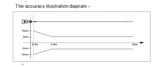
| Accuracy | ±10mm(See the accuracy illustration diagram below) |
| Temperature for Storage/Transport | (-40~80) ℃ |
| Process Temperature (Probe) | |
| 701、704 | (-40~250)℃ |
| 702 | (-40~200)℃ |
| 703 | (-40~130)℃ |
| 705 | (-200~400)℃ |
| Relative Humidity | <95% |
| Pressure | Max. 40MPa |
| Vibration Proof | Mechanical vibration 10m/s² , (10~150)Hz |
| Max Pulling Force | See the illustrative diagram on pulling force |
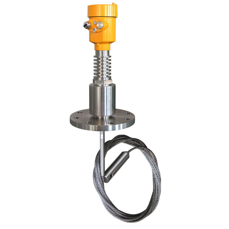
KD-801 radar level gauge is suitable for liquid, paste, granule and block material level and non-contact measurement, suitable for changes in temperature, pressure big; there is an inert gas and volatile.
The measurement method of microwave pulse, can work normally in the industrial frequency band range. The beam energy is low, can be installed on all kinds of metal, non-metallic container or pipe, no harm to human body and environment.
We are here to help you! If you close the chatbox, you will automatically receive a response from us via email. Please be sure to leave your contact details so that we can better assist