 Español
  pусский
  العربية
  Português
BETTER TOUCH BETTER BUSINESS
Contact Sales at KAIDI.
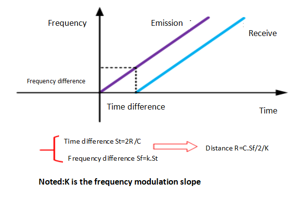
The general principle of the FM continuous wave radar level gauge is that the radar emits electromagnetic waves on the top of the tank, and the electromagnetic waves are received by the radar after being reflected by the medium. The frequency difference δf between the received signal and the transmitted signal is proportional to the distance R from the surface of the medium: R=C (speed)*δf (frequency difference)/2/K (frequency modulation slope). Because the speed of light C and the frequency modulation slope K are known, the frequency difference δf can be estimated to obtain the distance R from the radar installation position to the material surface, and then through the known total height of the tank, subtract the spatial distance from the radar to the material surface (referred to as Empty height) to get the height of the material level.
▶Small beam angle, concentrated energy, stronger anti-interference ability, higher measurement accuracy
▶Small size and light weight, easy to install
▶The protection level is up to IP68, which is suitable for a variety of water level measurement occasions.
▶The measurement range is up to 40 meters, covering large-scale reservoirs and other water level measurement
▶Multiple output circuit interfaces to cooperate with the acquisition system
Application: rivers, lakes, shallows
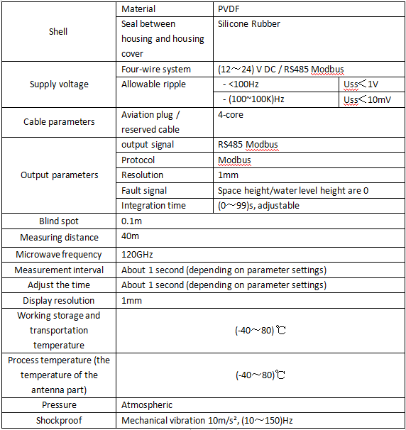
Measuring range: 40 meters
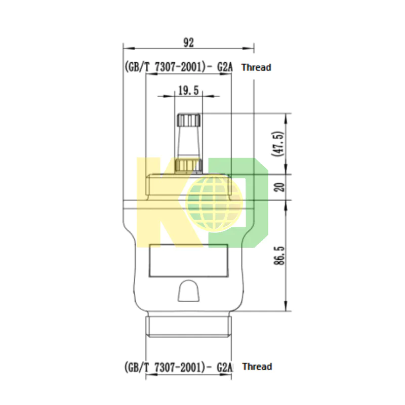
Process connection: Gantry frame, locking flange from DN65/ 2.5"
Process temperature: -40~80℃
Process pressure: (-0.1~0.3) MPa
Precision: ±2mm
Frequency range: 120GHz
Protection level: IP68
Antenna size: 42mm lens
Power supply: DC (12-24V) / four wires
Signal output: RS485
Commissioning: Bluetooth/Modbus protocol
Port rate: 115200
Elevation compensation: with
Temperature compensation: with
On-site display: None
Shell: Plastic PVDF
◉Preparation before installation
Please pay attention to the following items to ensure that the meter can be installed correctly:
Please reserve enough space for installation.
Please avoid installation situations with strong vibration.
◉Illustration and installation location
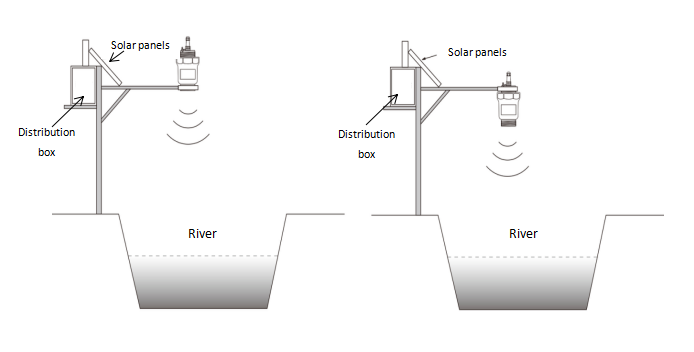
Radar water level gauge installation diagram (1)
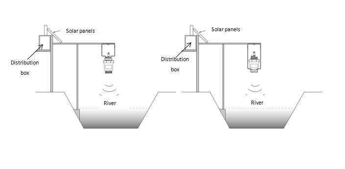
Radar water level gauge installation diagram (2)
Note: When a radar antenna emits microwaves, it has a certain emission angle. There should be no obstacles from the lower edge of the antenna to the surface of the measured medium, and in the area radiated by the emitted microwave beam. Therefore, shielding facilities should be avoided as much as possible during installation, and “false echo learning” must be carried out when necessary. Also pay attention when installing the instrument: the highest liquid level must not enter the blind area of the measurement.
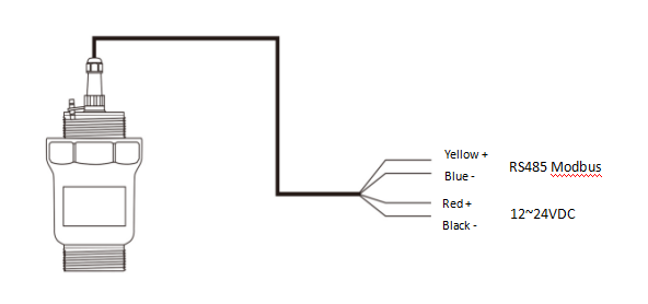
◉Supply voltage
Modbus-RS485
Separate the power supply and Modbus signal lines with a shielded cable respectively. For the specific power supply voltage range, please refer to the technical data.
◉Safety guidance
Please comply with the requirements of local electrical installation regulations!
Please abide by the local regulations on the health and safety of personnel. All operations on the electrical components of the instrument must be completed by properly trained professionals.
Please check the nameplate of the meter to ensure that the product specifications meet your requirements. Please make sure that the power supply voltage is consistent with the requirements on the nameplate of the meter.
◉Protection level
This meter fully meets the requirements of protection class IP68, please ensure the waterproofness of the cable sealing head. As shown below:
How to ensure that the installation meets the requirements of IP68:
Make sure that the sealing head is not damaged.
Make sure that the cable is not damaged.
Make sure that the cables used meet the requirements of the electrical connection specifications.
Before entering the electrical interface, bend the cable downward to ensure that water does not flow into the housing.
Please tighten the cable gland.
Please block the unused electrical interfaces with blind plugs.
◉There are two debugging methods for radar water level gauge:
(1)Mobile phone Bluetooth debugging/connecting to the Bluetooth debugging radar through the WeChat applet
(2) Host computer debugging/debugging through MUDBUS protocol
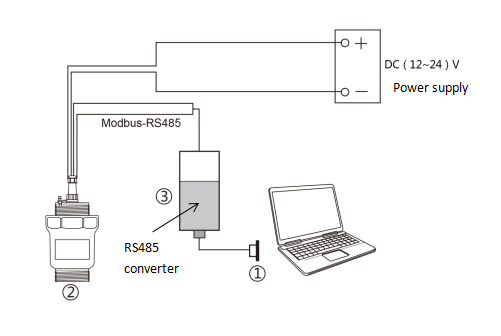
◉Upper computer debugging
➱Connect to the host computer through the RS485 converter
① RS232 interface/or USB interface
② Radar water level gauge
③ RS485 converter
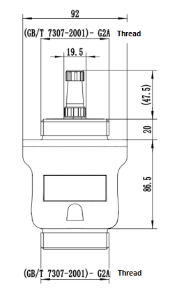
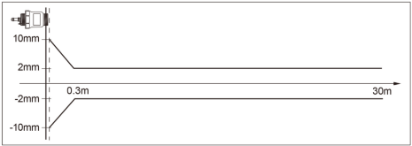
The launch angle depends on the antenna size
-¢42mm 5°
Accuracy see the figure below
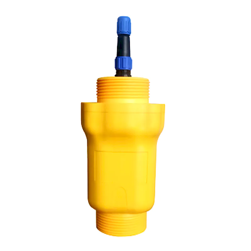
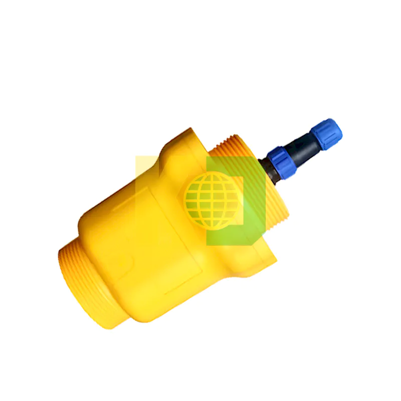
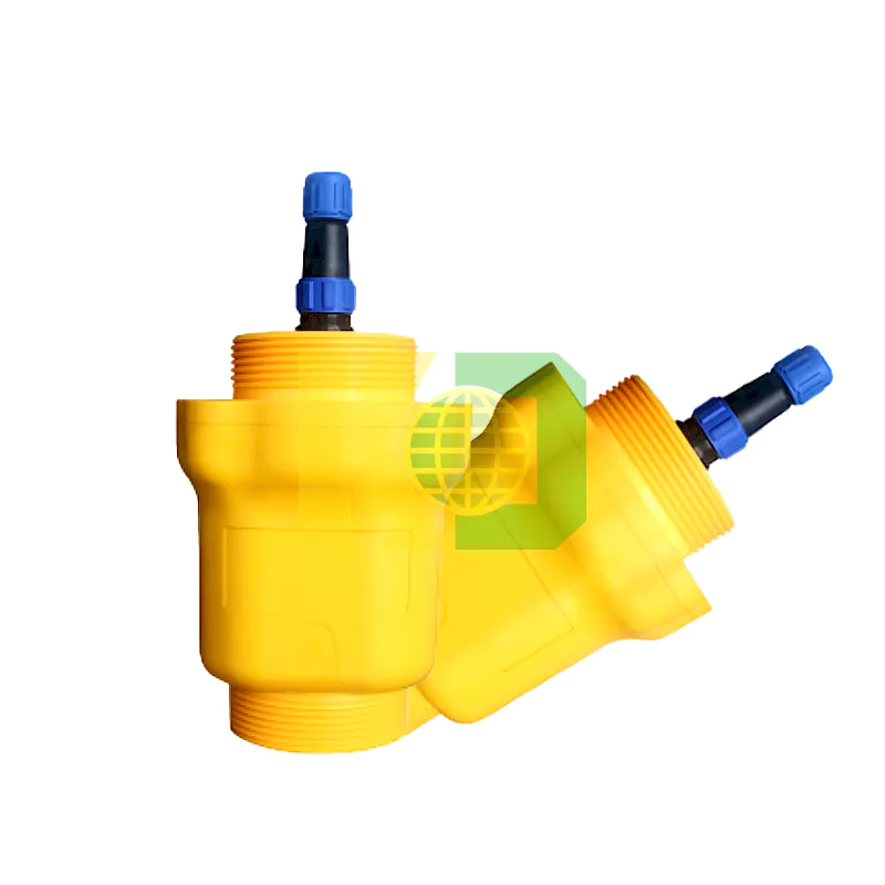
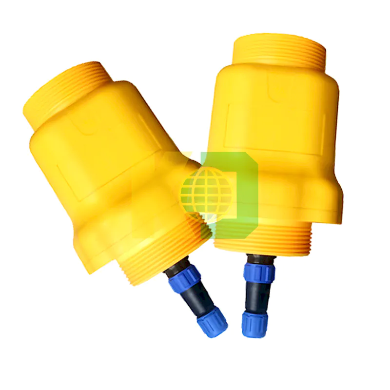
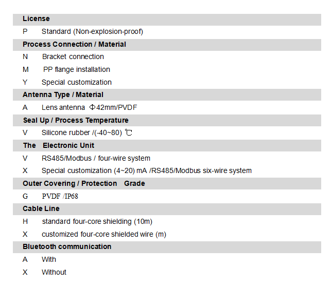
◉ Model:KDR-908ZT
We are here to help you! If you close the chatbox, you will automatically receive a response from us via email. Please be sure to leave your contact details so that we can better assist

