Español
  pусский
  العربية
  Português
 PC software debugging:
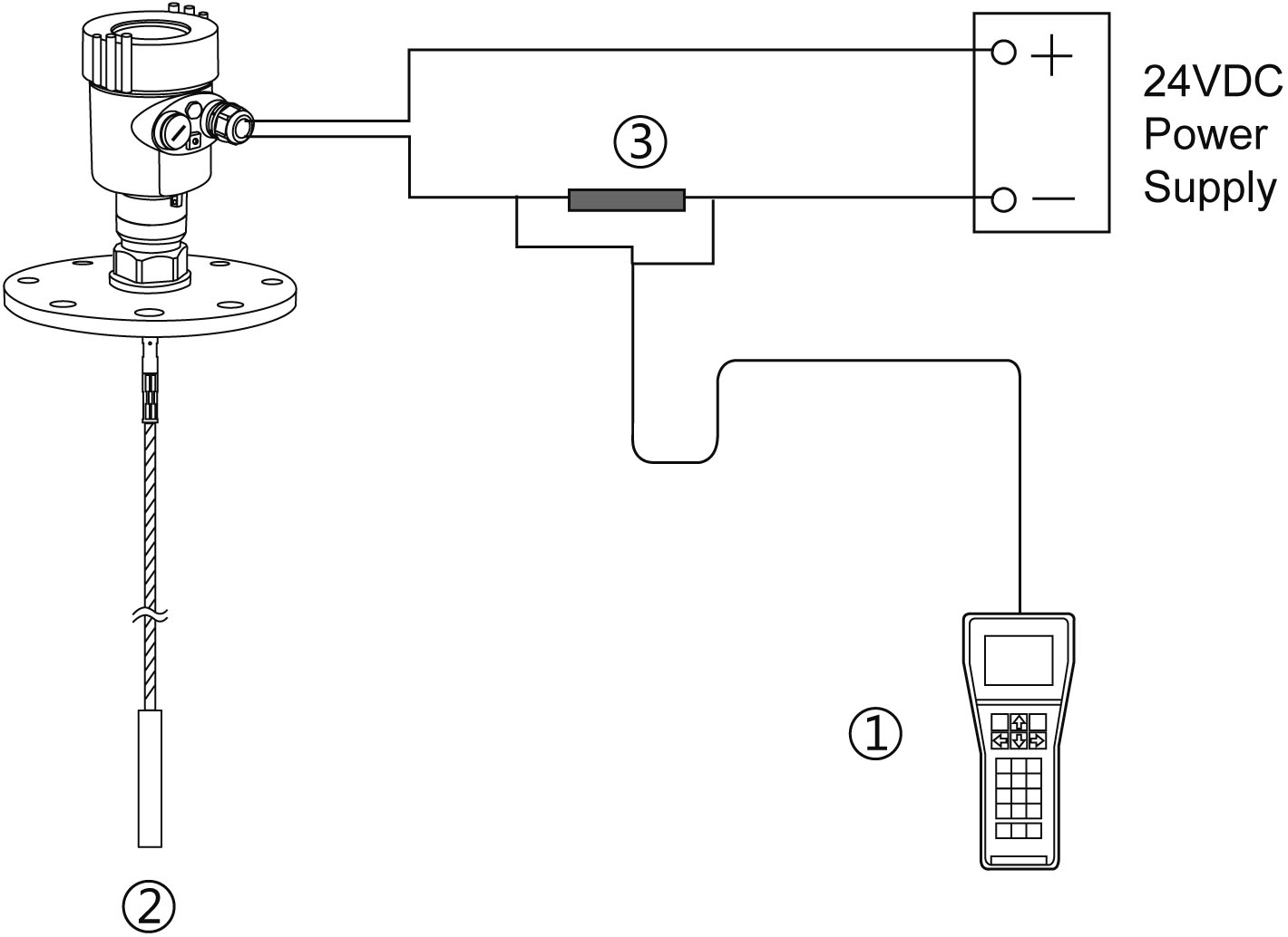
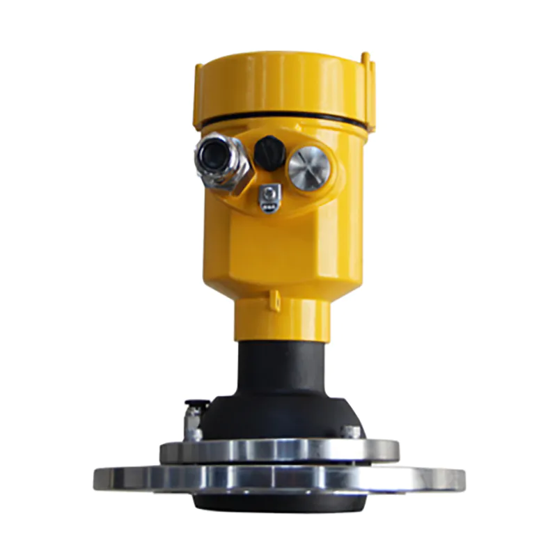
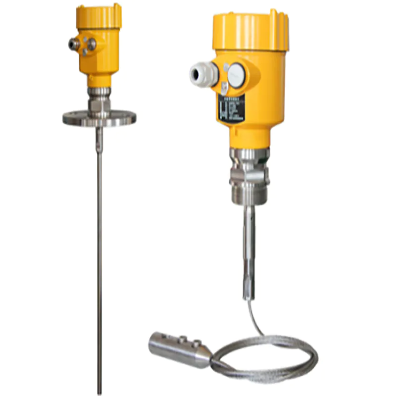
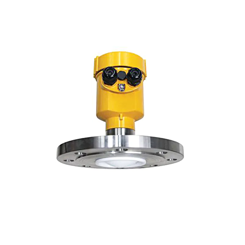
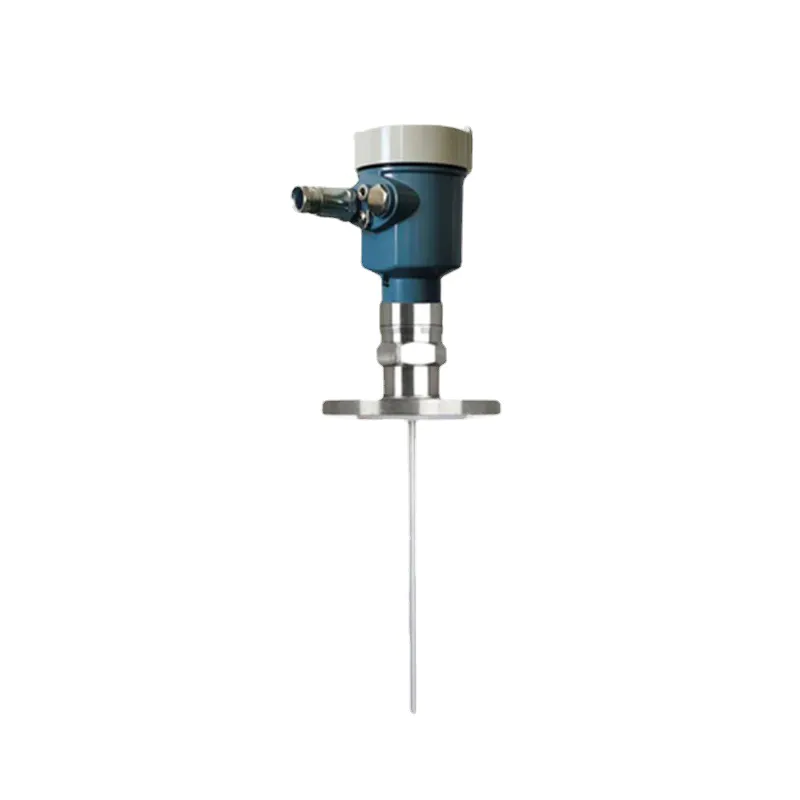
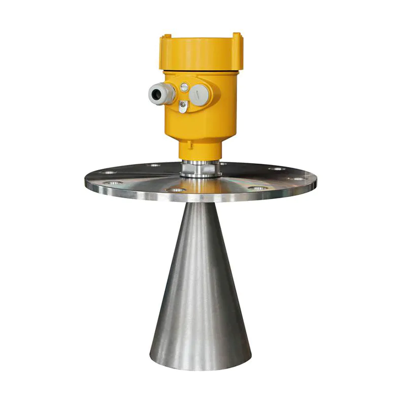
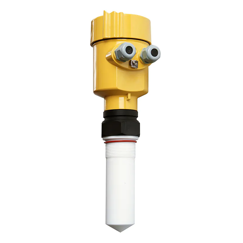
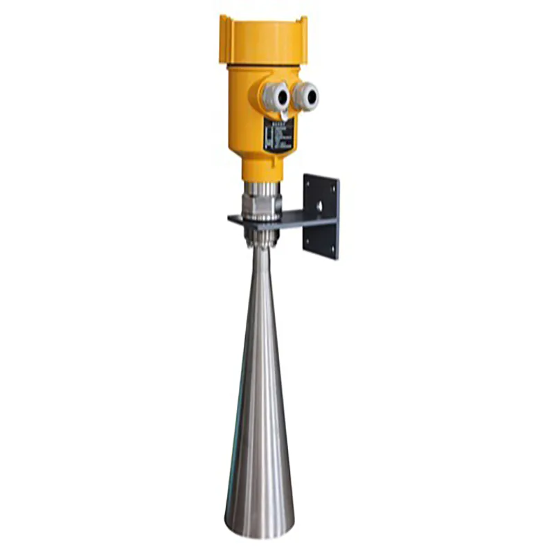
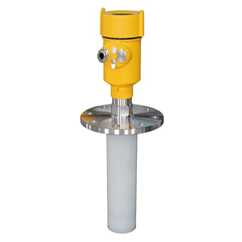
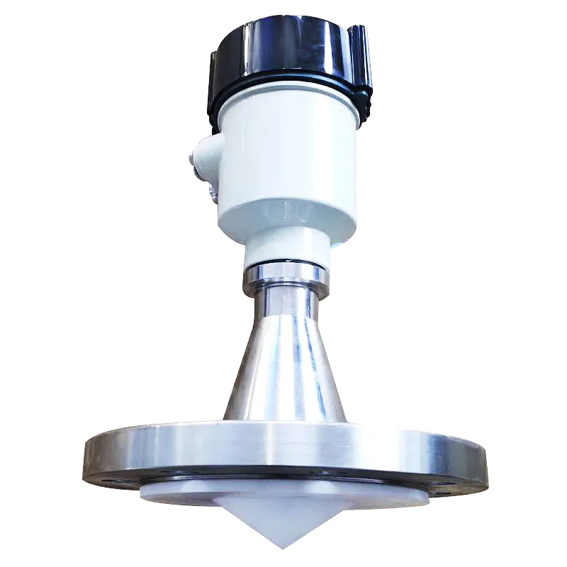
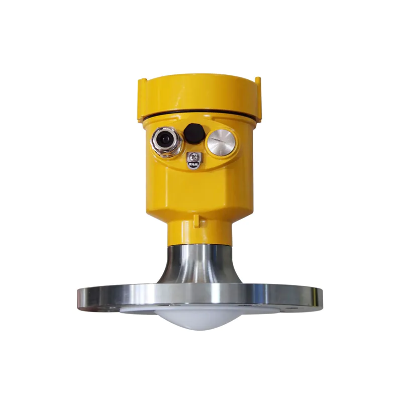
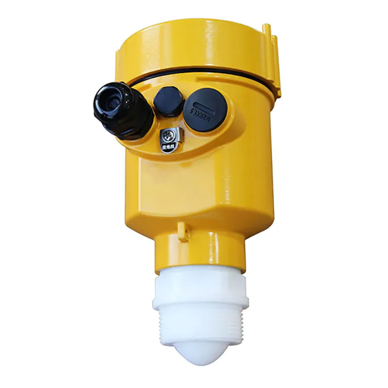
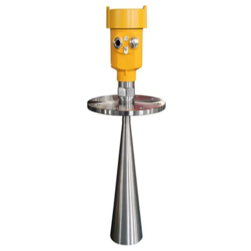
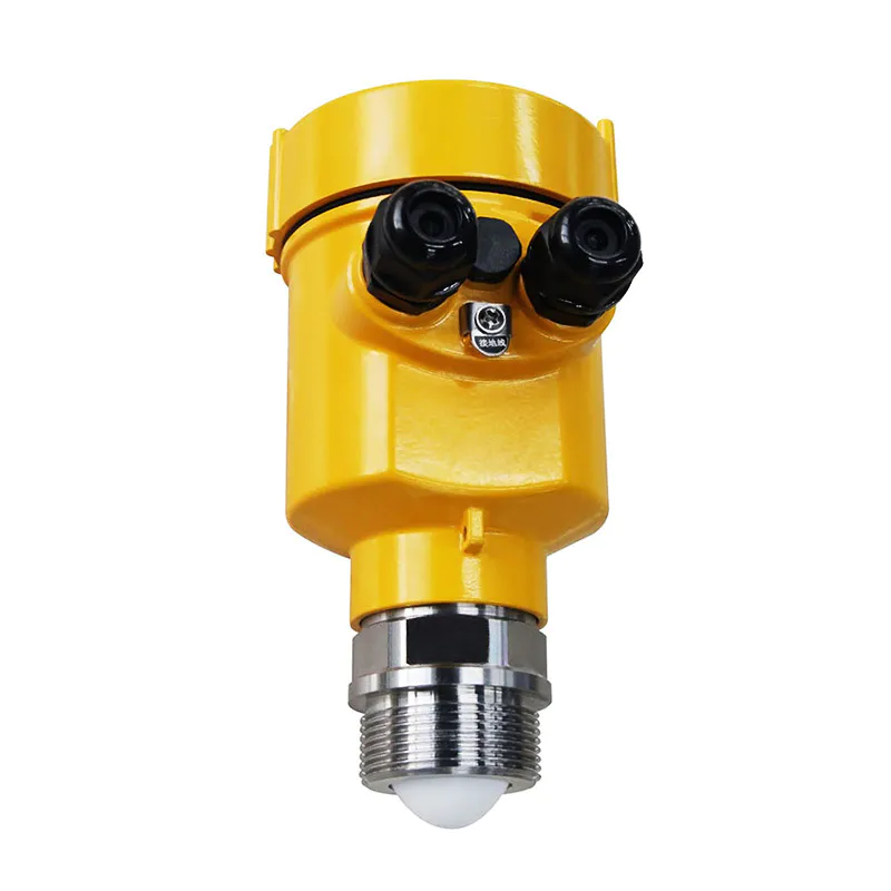
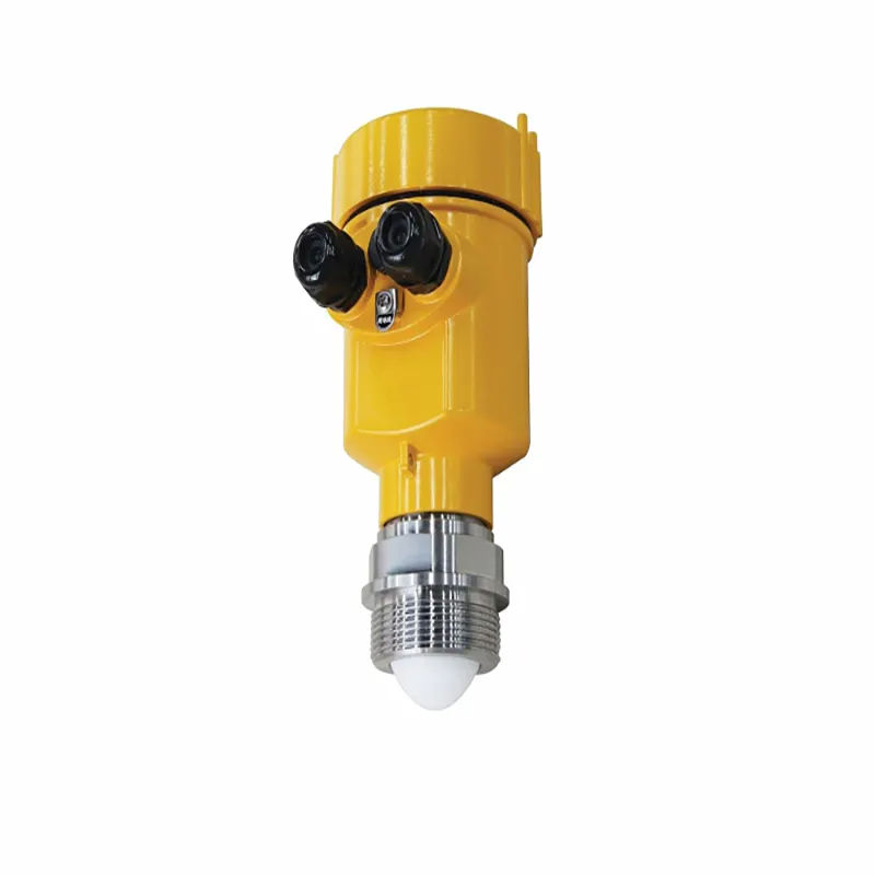
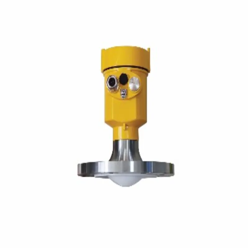
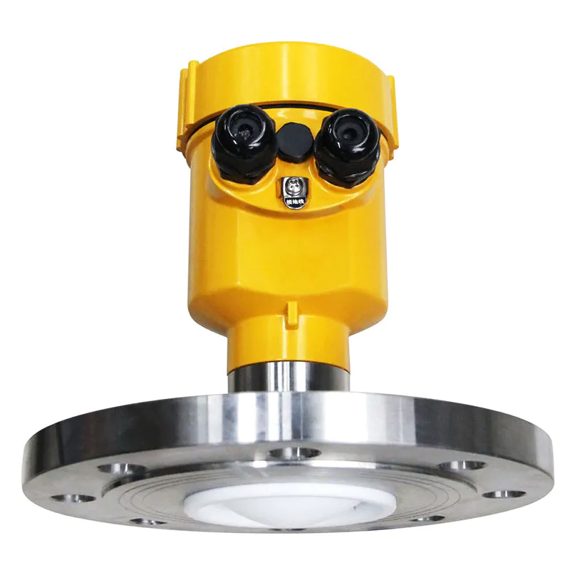
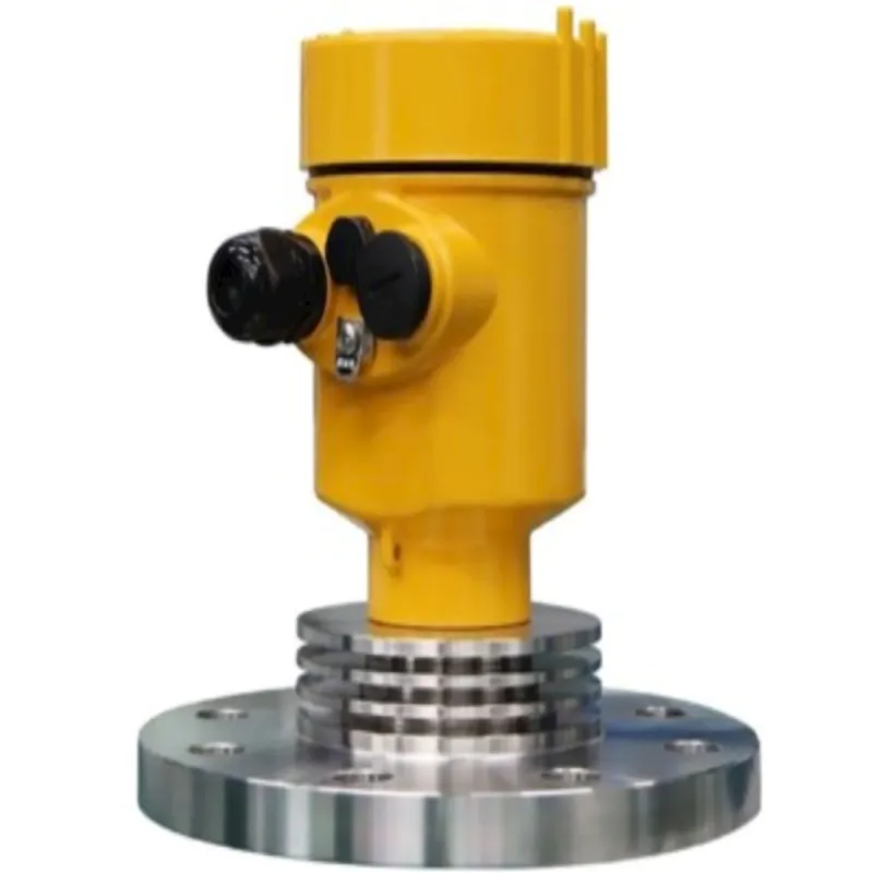
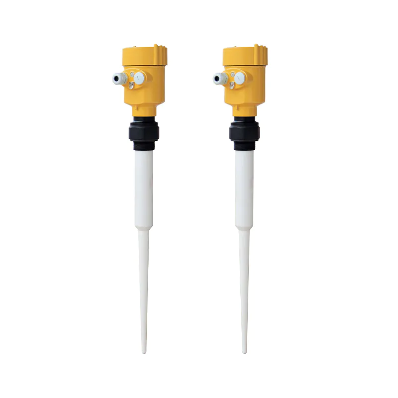
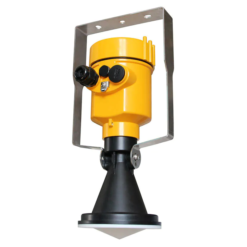
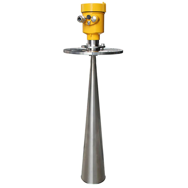
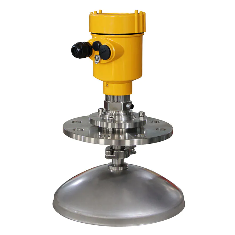
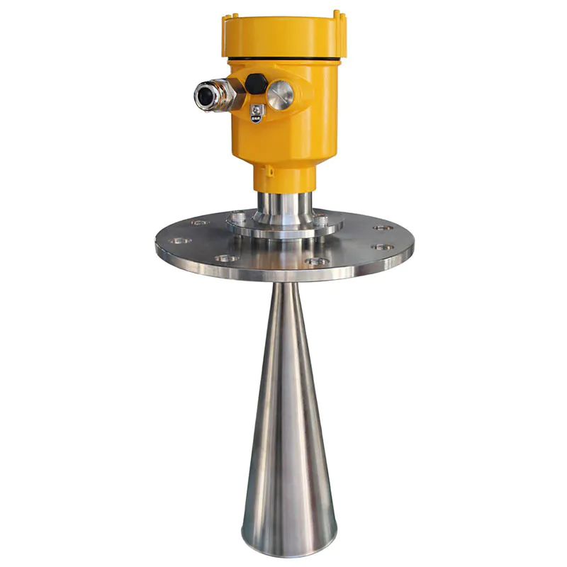
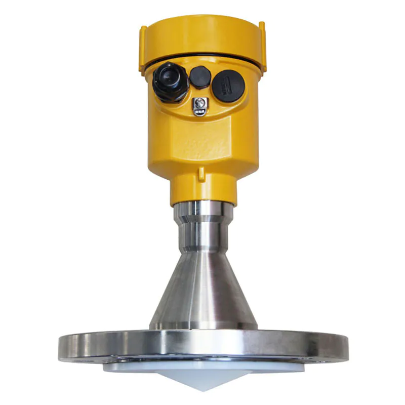
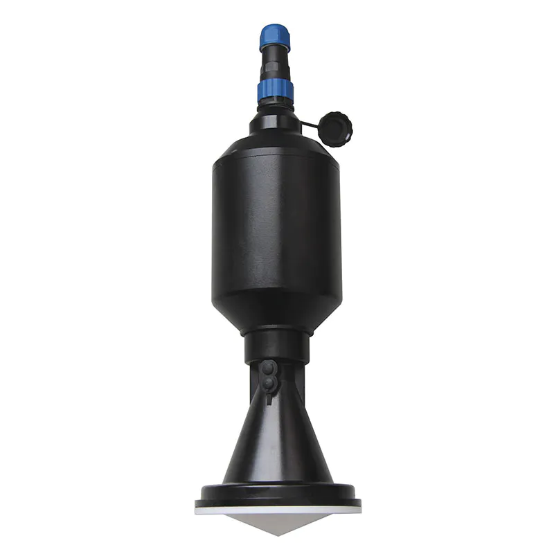
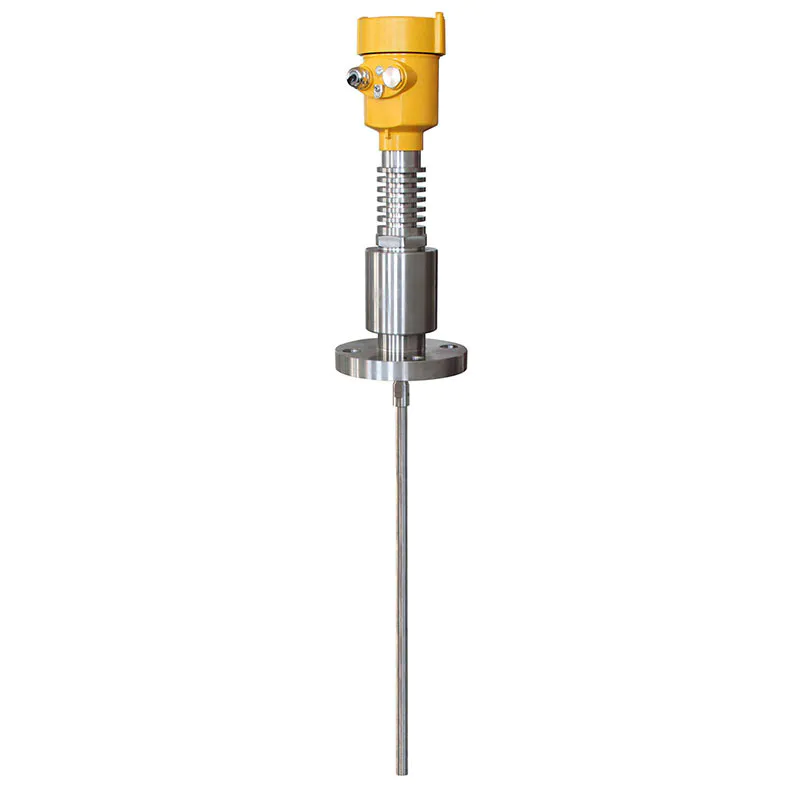
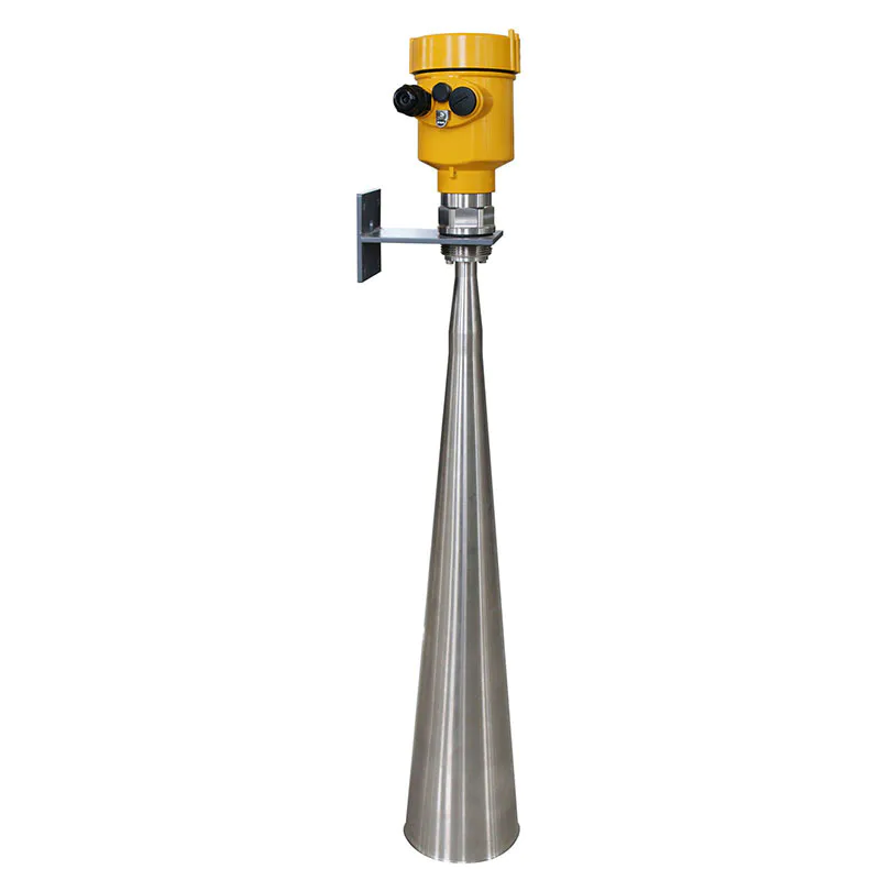
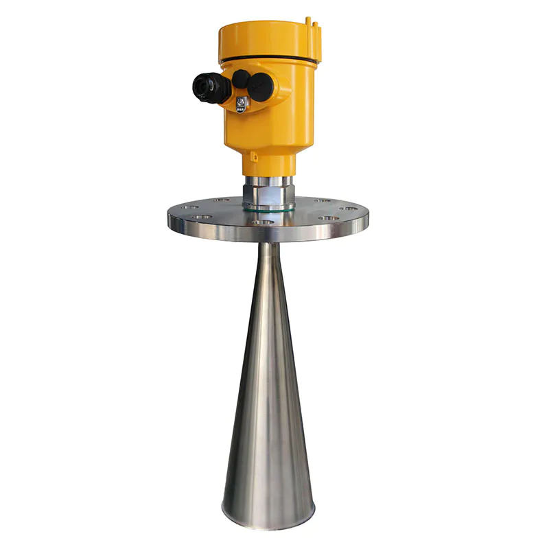
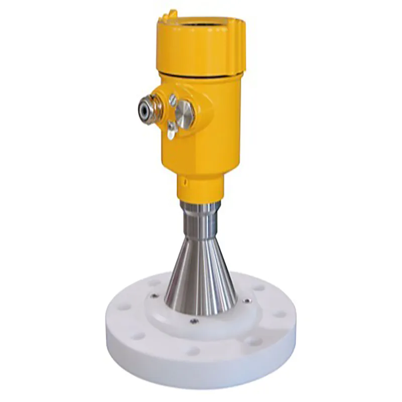
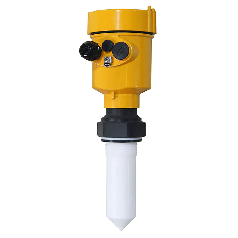
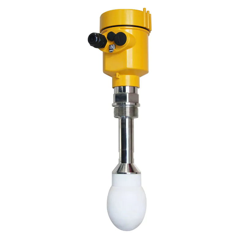
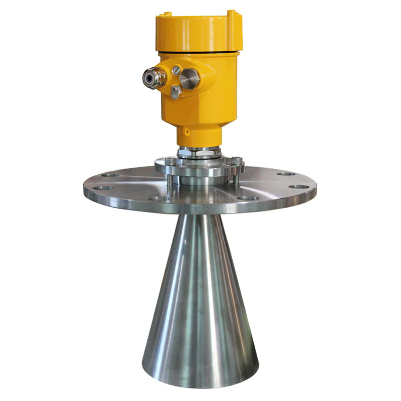
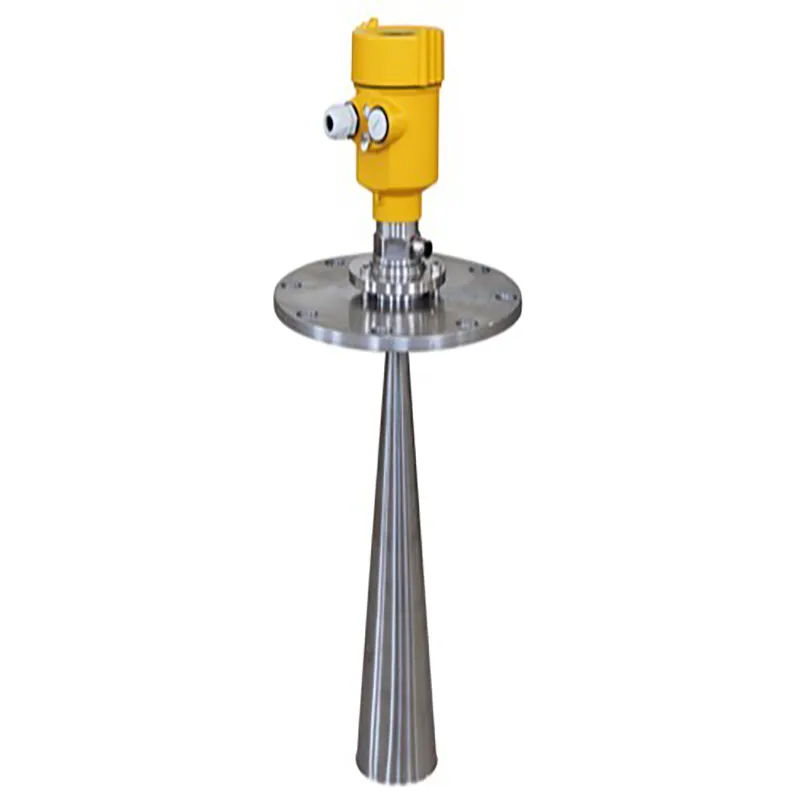
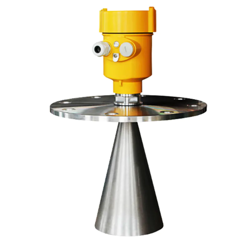
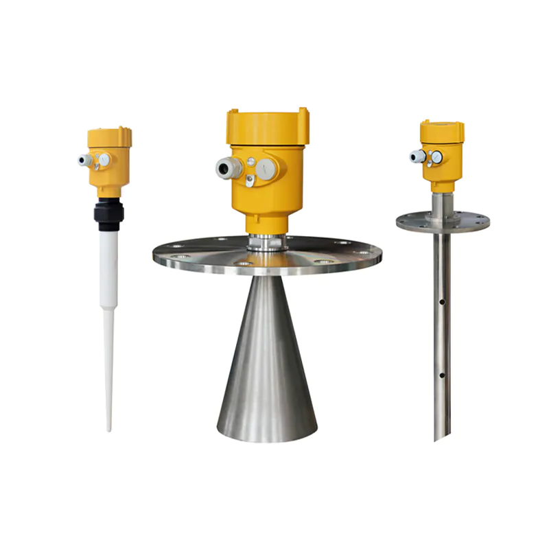
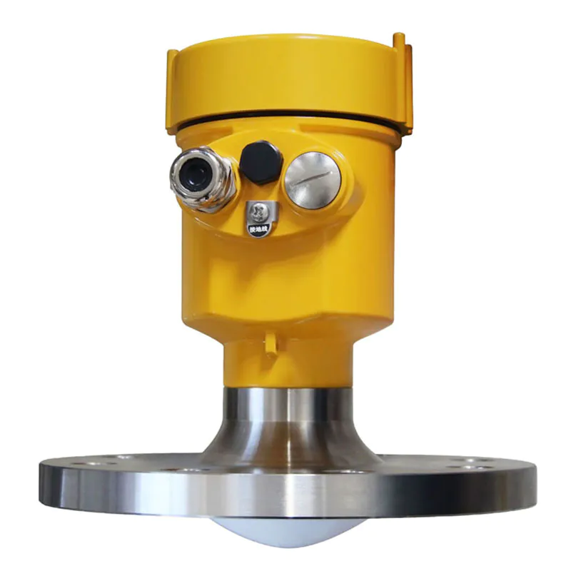
Radar Level Meter 80G FM Radar Type Level Measuring Instrument Kaidi KD-FMW21S FM
KDRD-FMW Series Sensor Is 80G FM Radar Type Level Measuring Instrument, Measuring Distance Up To 150 Meters


Measurement Principle
Principle:
High-frequency microwave pulses issued by the guided wave radar propagate along detection components (steel cable or steel rod), met the media to be measured, since the dielectric constant of the mutation, cause reflections, a portion of the pulse energy is reflected back. Transmit pulse and the reflected pulse is proportional to the distance and the time interval measured media.
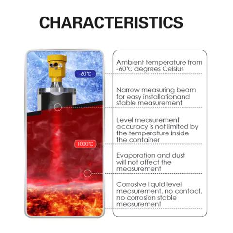
Features:
As a result of advanced microprocessor and unique Echo Discovery echo processing technology, guided wave radar level meter can be used in a variety of complex conditions.
Because of the type of process connections and detection components, making Guided Wave Radar Level Meter is suitable for a variety of complex conditions and applications. Such as: high temperature, high pressure and low dielectric constant media.
Pulsed work, guided wave radar level instruments transmit power is very low, can be installed in a variety of metals, non-metallic container, no harm to humans and the environment.
Explanation:
Guided Wave Radar is a time travel to the principle of measuring instruments, radar run at the speed of light, the running time can be converted into a level signal by electronic components. When the pulse reaches the surface of the material, the pulse is reflected back and is received by the receiving container inside the instrument, the distance the signal is converted to level signals.
Reflected pulse signal along the cable or rod probe type transmit to the instrument electronic circuit parts, the microprocessor processes the signal, identify the microwave pulse echo generated in the material surface. Correct identification of the echo signal are completed the implementation by the pulse software,D, the distance from the material surface and the pulse travel time T is proportional:
 D=C×T/2
Where C is the speed of light
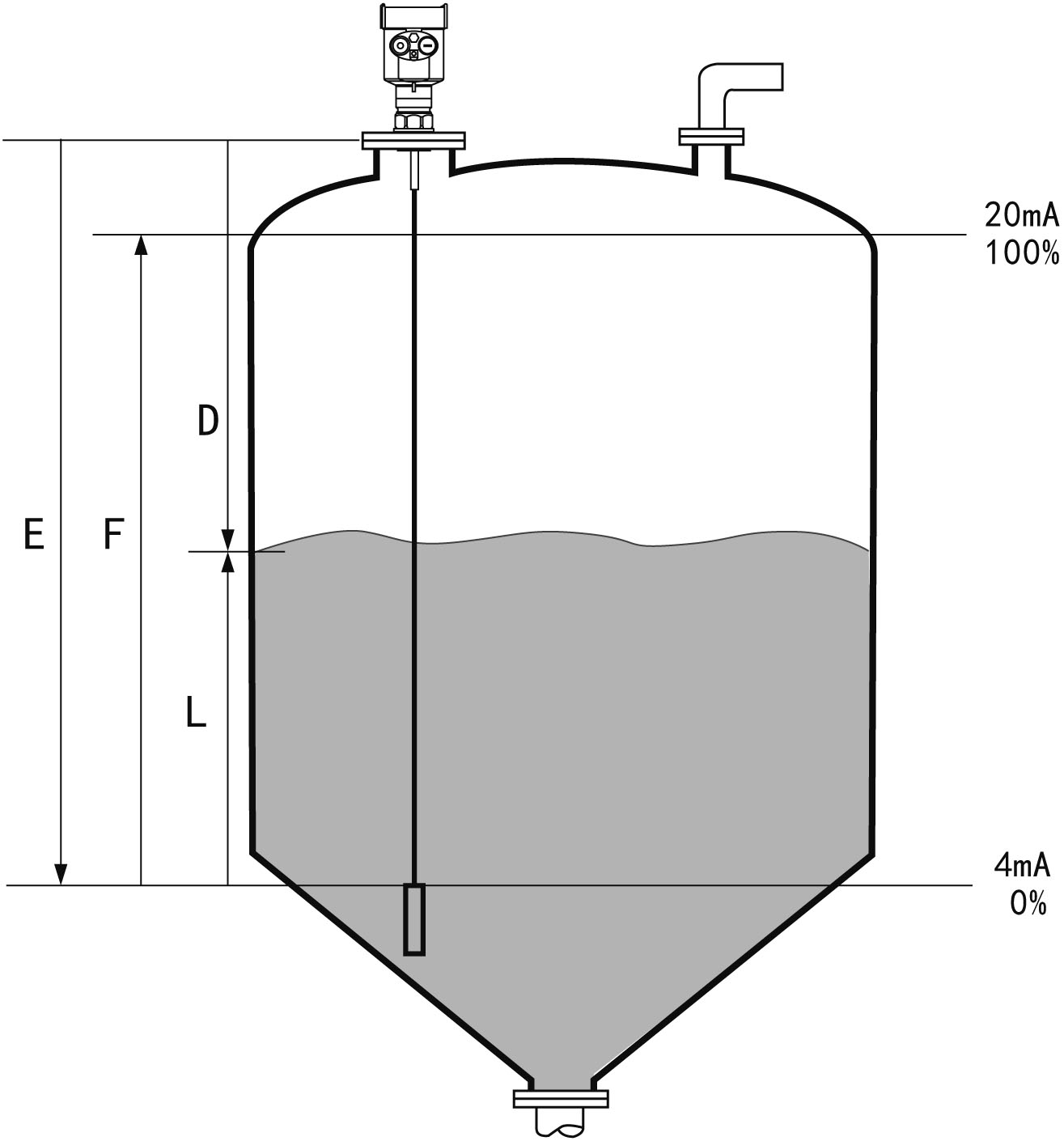
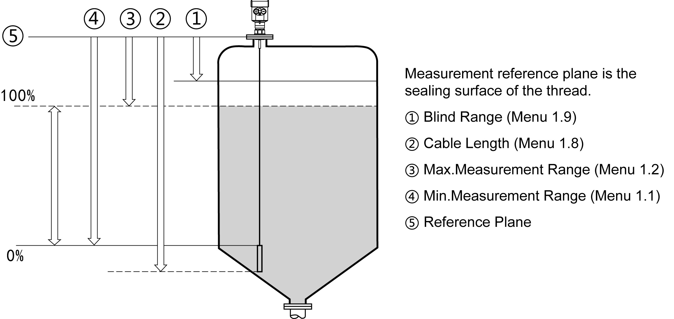
Because the empty distance E is known, the level L is:
L=E-D
By entering the empty height of E (= zero), full tank
height F (= hundred) and the application to set
some parameters, application parameters will
automatically adapt the instrument to measure
the environment, corresponding to the 4-20mA
output.
Measuring range:
--Blind spot is the minimum distance between the top of the highest material surface materials and measurement reference point.
--The bottom of the blind refers to a distance near the very bottom of the cable can not be accurately measured.
--Between the top and bottom of the blind is blind effective measure distances.
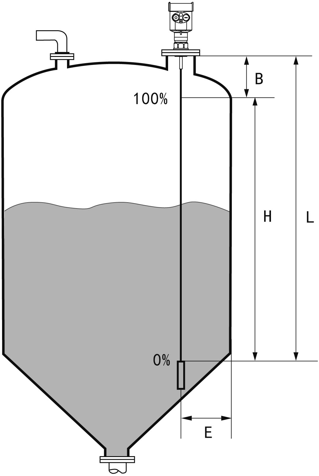 Explanation:
H--- Measuring range
L---Empty distance
B---The top of the blind
E---The minimum distance from the probe
to the tank wall
Note:
In order to ensure the accuracy of level measurement,
the material should be located between the top and
bottom of the blind the blind.
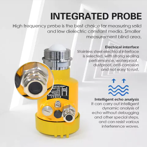
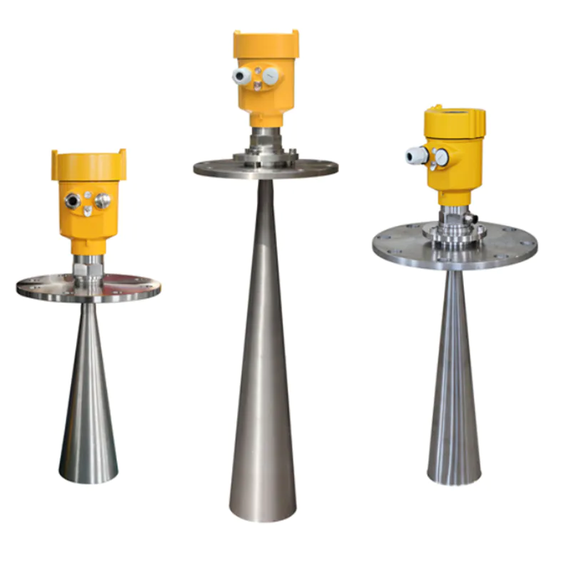
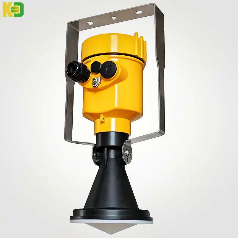
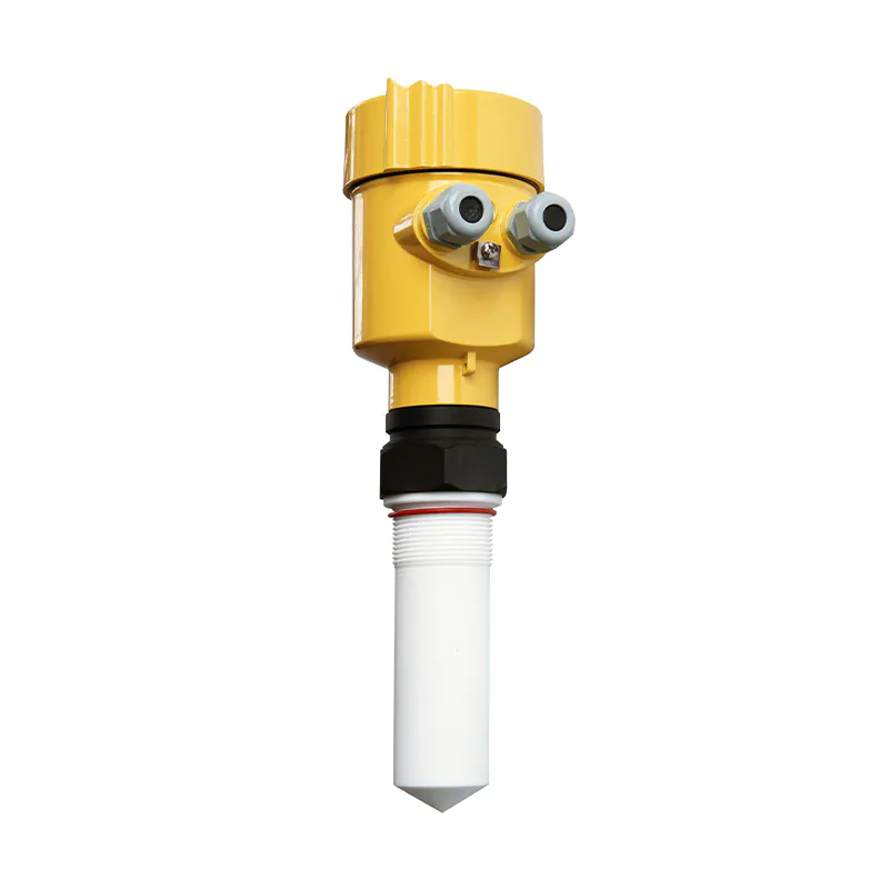
Product Introduction
705
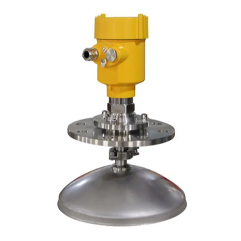
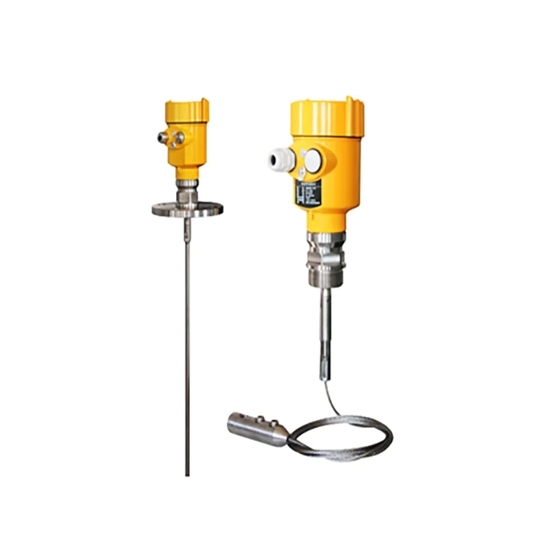
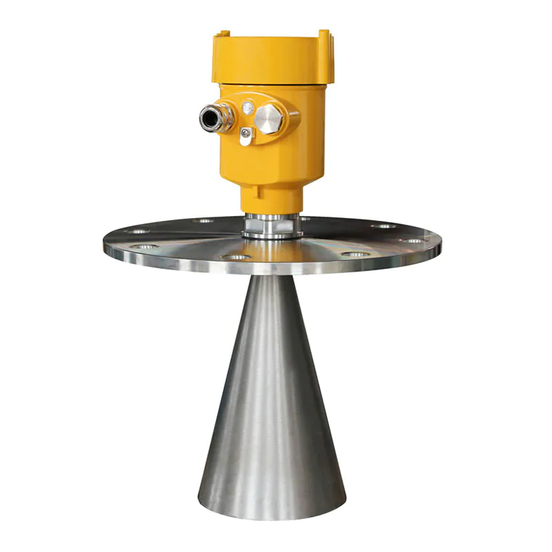
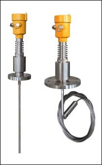 Suitable for Medium: Liquids, especially high
temperature and pressure environment of liquid
Application: Sealed cans,
greater pressure liquid measurement
Explosion-proof Grade: Exia IIC T6 Ga/Exd IIC T6 Gb
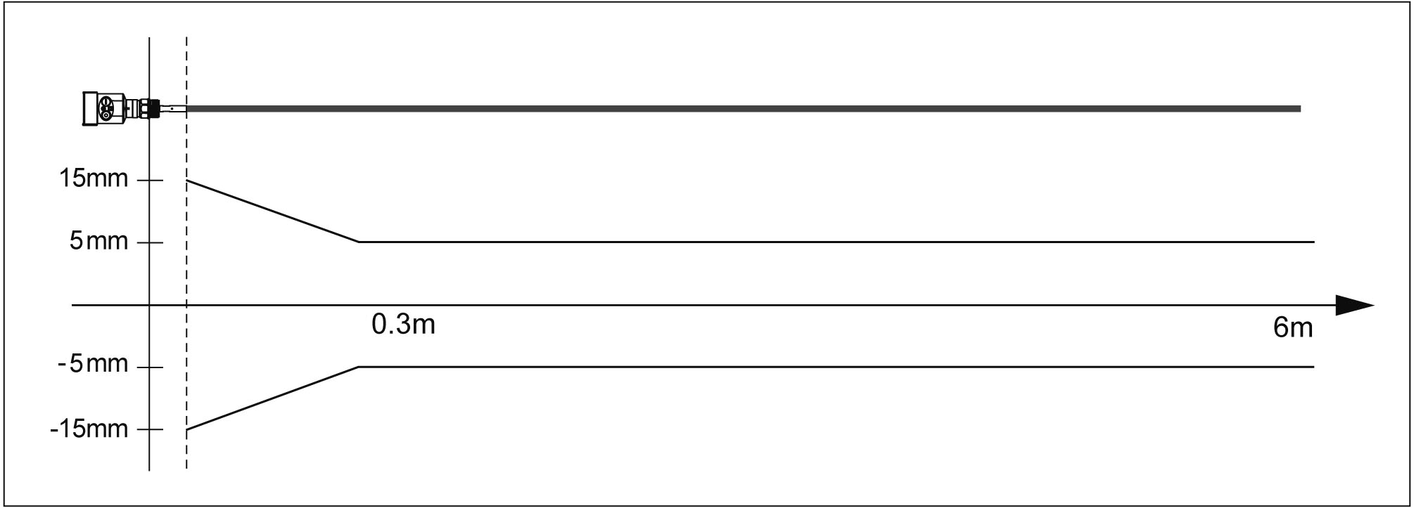
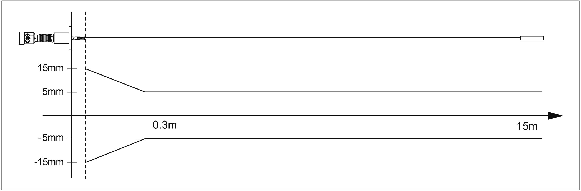
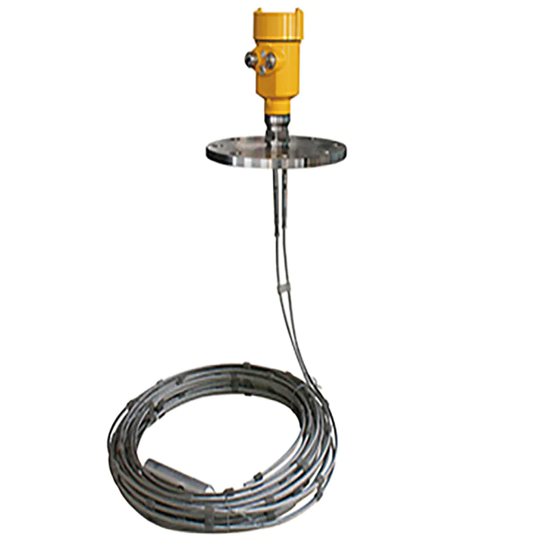
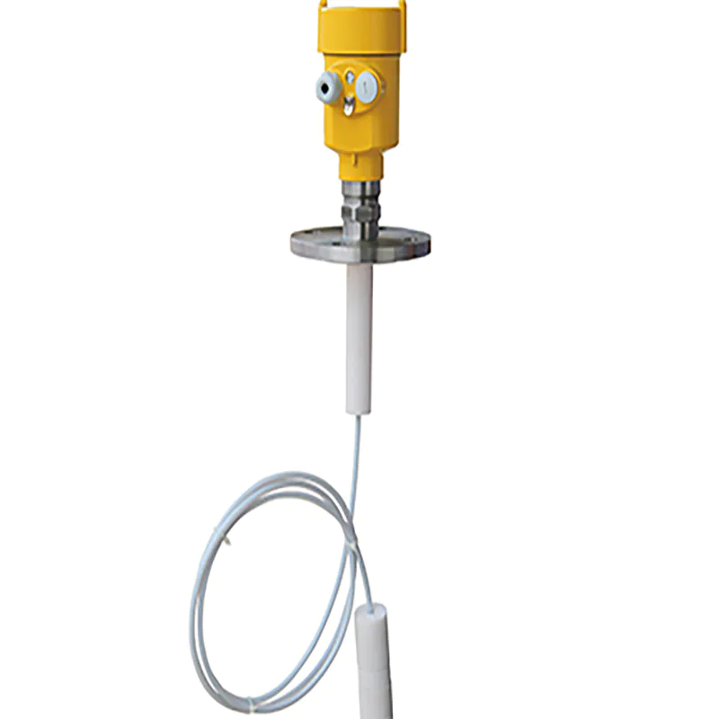
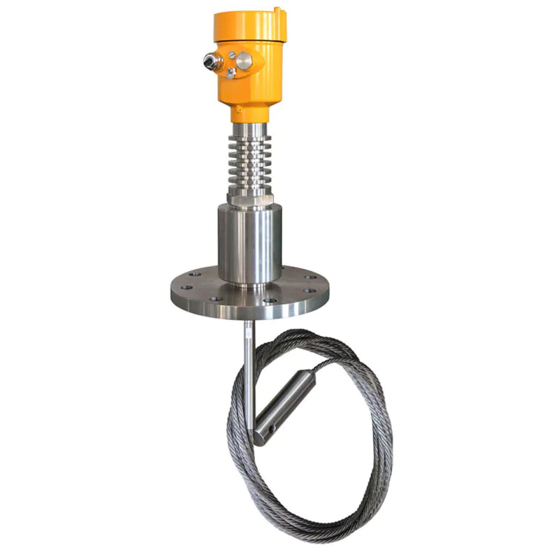
Measuring Range: cable style 15m / rod style 6m
Frequency: 500MHz-1.8GHz
Antenna: Single cable or single rod antenna
Accuracy: ±5mm
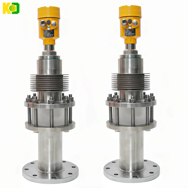
Process Temperature:(-200~400)℃
Process pressure:(-0.1~40)MPa
Signal output: (4~20)mA Hart / RS485 Modbus
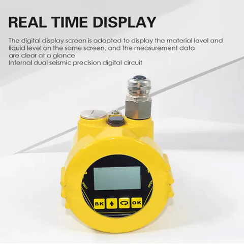
The Scene Display: Four LCD/Can be programmed
Power Source: Two-wire (DC24V)
Four-wire(DC24V/AC220V)
Outer casing: Aluminum / Plastic / Stainless Steel
Connection: Thread / Flange (optional)
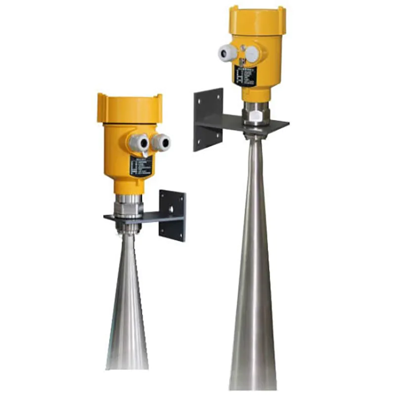
Installation Guide
Within the measurement range, determined not to come into contact with the cable or rod internal obstacles, Therefore, the installation should be avoided as far as possible the tank facilities, such as: human ladder, limit switches, heating devices, stand etc. Also note that the cable or rod may not intersect with the material during feeding.
Installation Precautions:
Highest Level measurement can not enter into the blind; Must be maintained between the instrument and the tank wall a certain distance; When the meter is installed, try to stick with cable or perpendicular to the surface of the measured medium. Meter installation in hazardous areas must comply with state regulations explosion hazardous installation area. Intrinsically safe instrument requires the use of shell with aluminum. Intrinsically safe instrument can be installed in explosion-proof requirements of the occasion, the instrument must be connected to the earth.
Installation position:
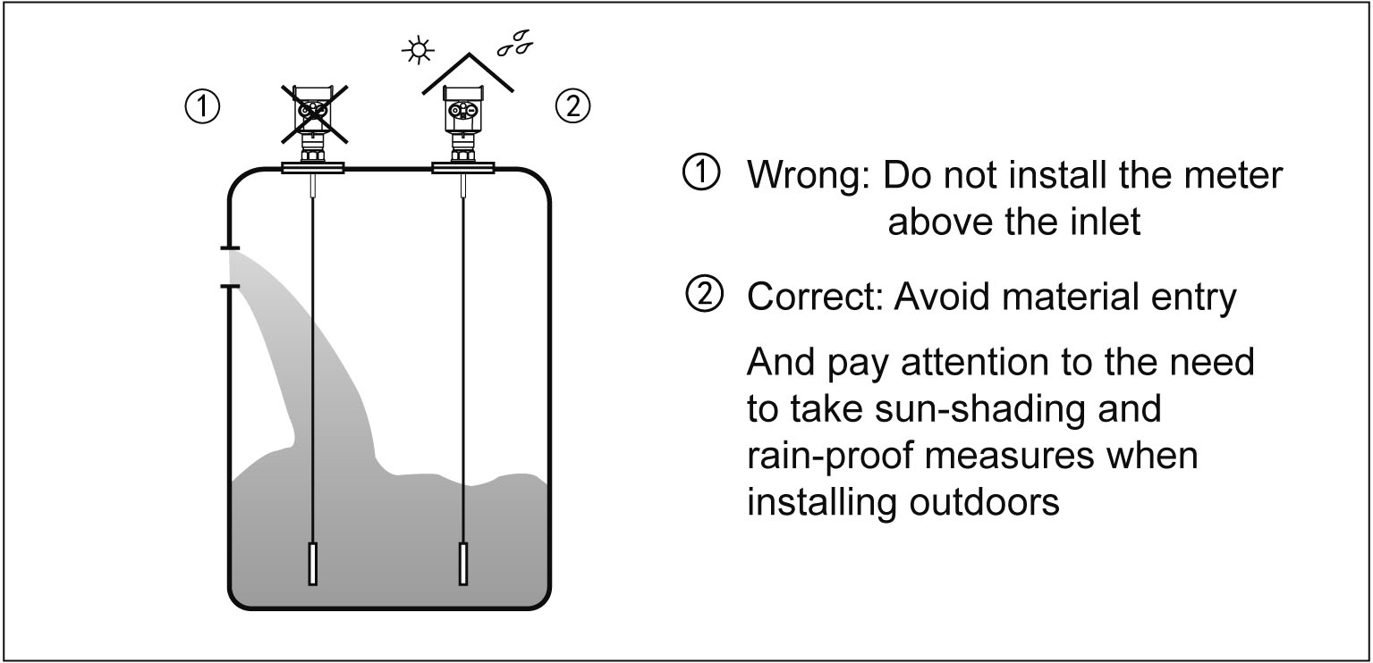
 Ø Far away from the discharge port and inlet.
Ø Metal cans in the entire measuring range, not to touch the tank wall and tank bottom.
Ø Recommended meter installed in 1/4 or 1/6 of the silo diameter, and the minimum
distance is 1/10 of the tank wall of the measuring range.
Ø Cable type or rod probe the minimum distance from the tank wall ≥300mm.
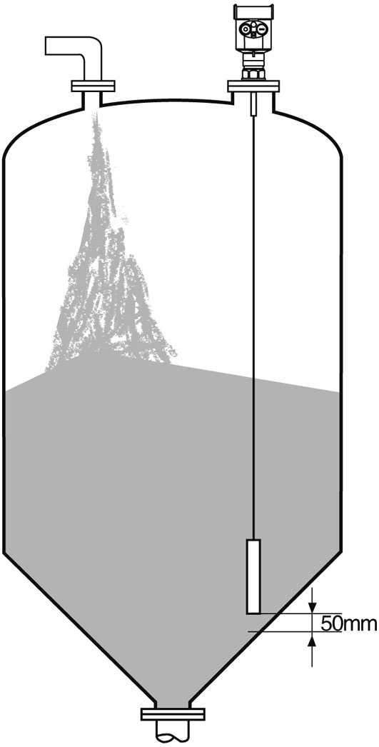
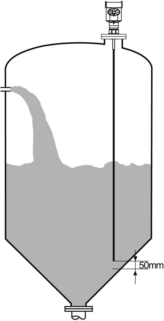
Ø Bottom of the probe from the tank bottom ≥30mm.
Ø The minimum distance from the probe obstructions ≥200mm.
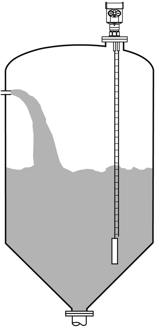
Ø If the bottom of the container is a cone, you can install a central tank top.
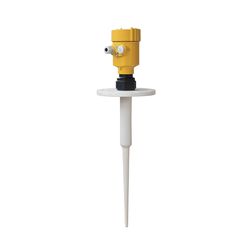
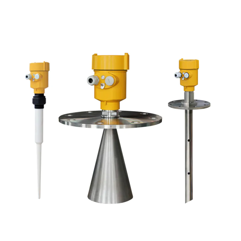
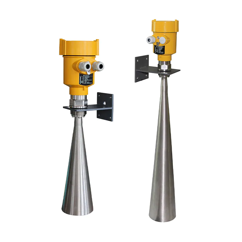
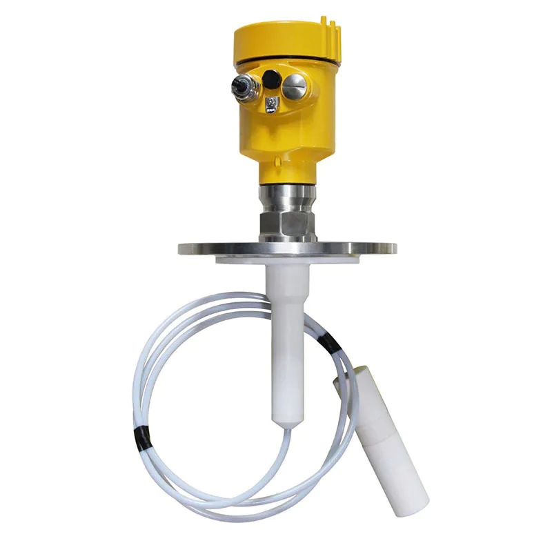
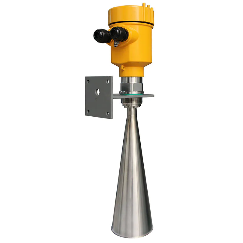
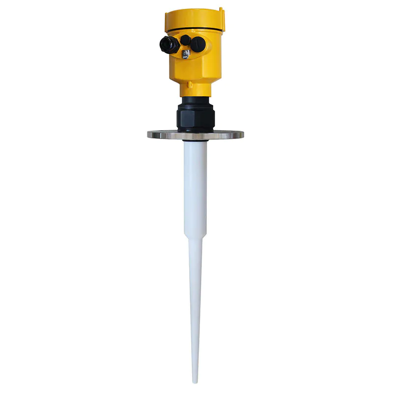
Measurement characteristics of rod radar level:
 Ø You can measure any dielectric permittivity of ≥1.8 .
Ø Generally used to measure viscosity ≤500cst, not prone to adhesion medium.
Ø Rod radar maximum range of 6 m.
Ø Instrumentation for steam and foam has a strong penetrating power, the measurement is not affected.
Ø For a lot of foam liquid measurement environment, you should select a single rod
guided wave radar level meter measurement.
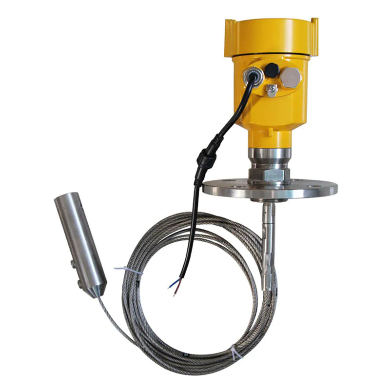
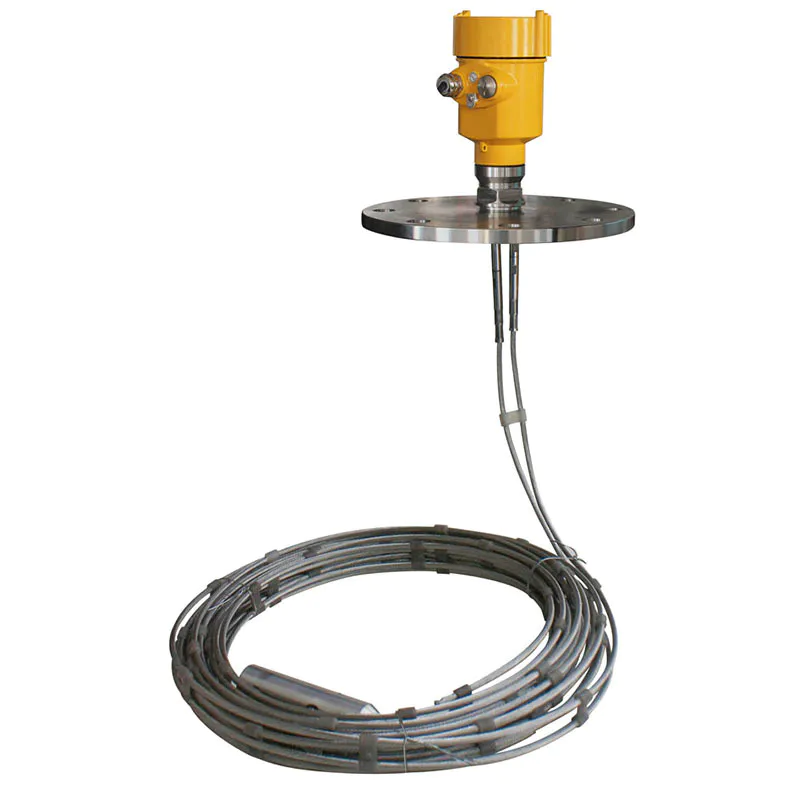
Measurement characteristics of dual-cable radar level meter:
 Ø For low dielectric constant of the liquid and light solid powder, can double cable measurement mode,
in order to ensure accurate measurements.
Ø You can measure the dielectric constant of ≥1.6 in any medium.
Ø Generally used to measure viscosity ≤500cst, not prone to adhesion medium.
Ø Double cable radar level meter maximum range of up to 30 meters.
Installation Method:
Ø Reasonable meter installation to ensure long-term reliable and accurate measurement
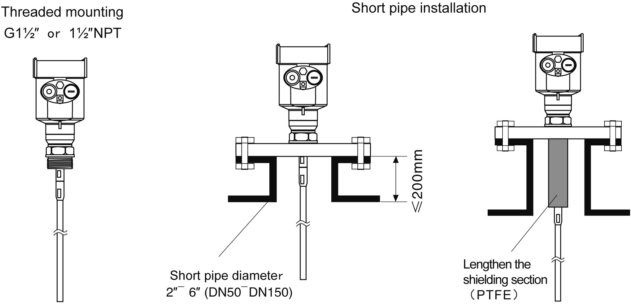
Guided wave radar level meter adopts thread and flange connection and can be installed on short pipe. The smaller the diameter of the installation pipe, the shorter the pipe length, and the more stable the measurement. When the diameter of the installation short pipe is 2" to 6", the height of the installation short pipe should be ≤200mm. If the short tube is long, it is best to shorten the short tube or lengthen the sensor shielding section.
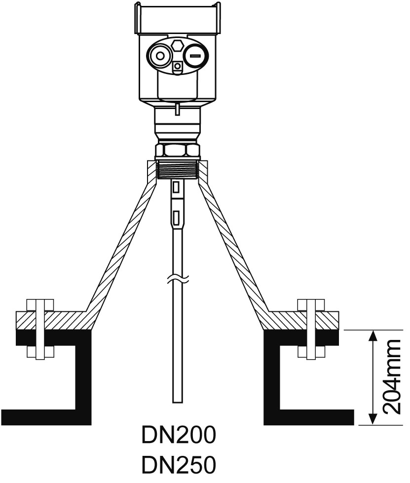
Ø Installation in short pipe of DN200 or DN250:
When the guided wave radar is installed on a short tube with a diameter greater than 200mm, the inner wall of the short tube will generate echoes, which may easily cause measurement errors due to the low dielectric constant of the medium. Therefore, for a short pipe with a diameter of 200mm or 250mm, a special flange with a "horn interface" needs to be selected.
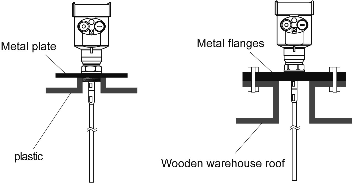
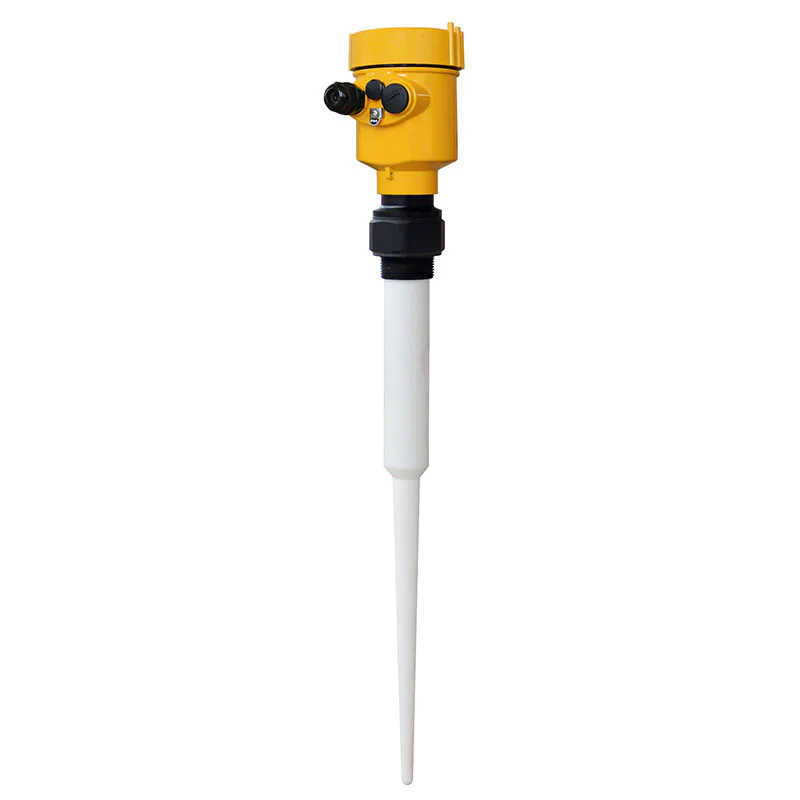
Ø Installation Notes on plastic containers:
Whether cable or rod type, if you want to guided wave radar is working properly, the process of connecting to the metal surface should be. When the guided wave radar mounted on a plastic pot, If the tank top is plastic or other non-conductive material, the instrument needs with metal flanges, the use of threaded connections, to be equipped with a metal plate.
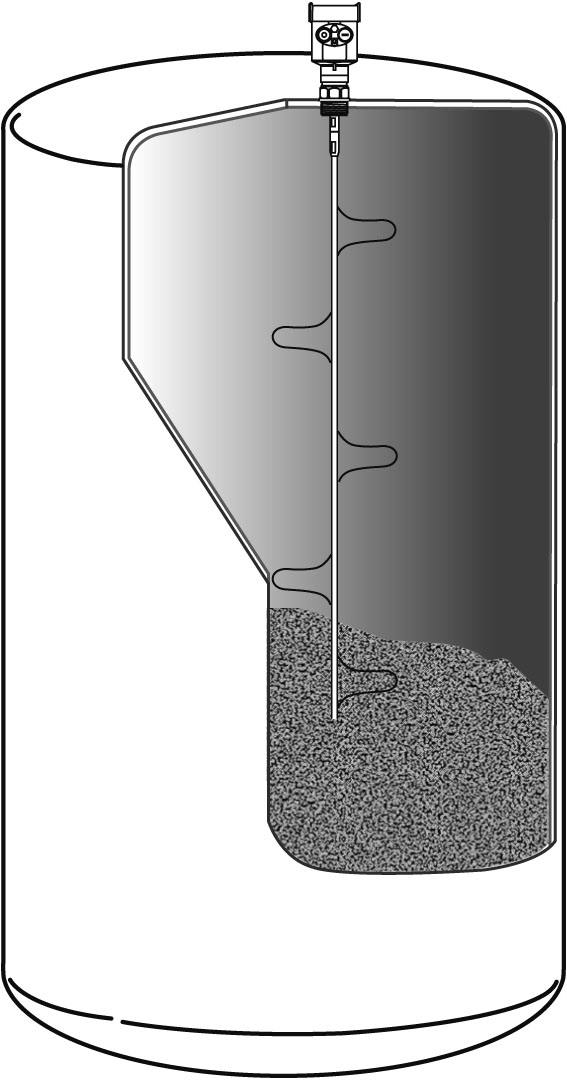
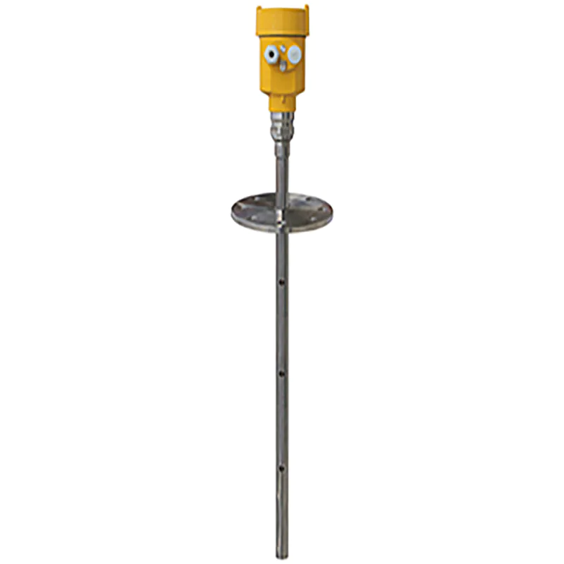
Installation instructions
The rod probe can be up to 6 meters long. For storage tanks with a measuring distance of more than 6 meters, cable probes are used.
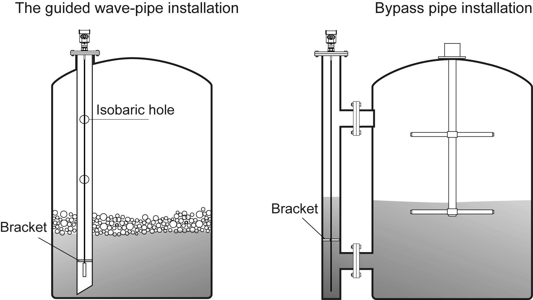
If there are many obstacles in the tank or the probe is easily approached to the sensor, the guided wave-pipe device can be added for measurement.
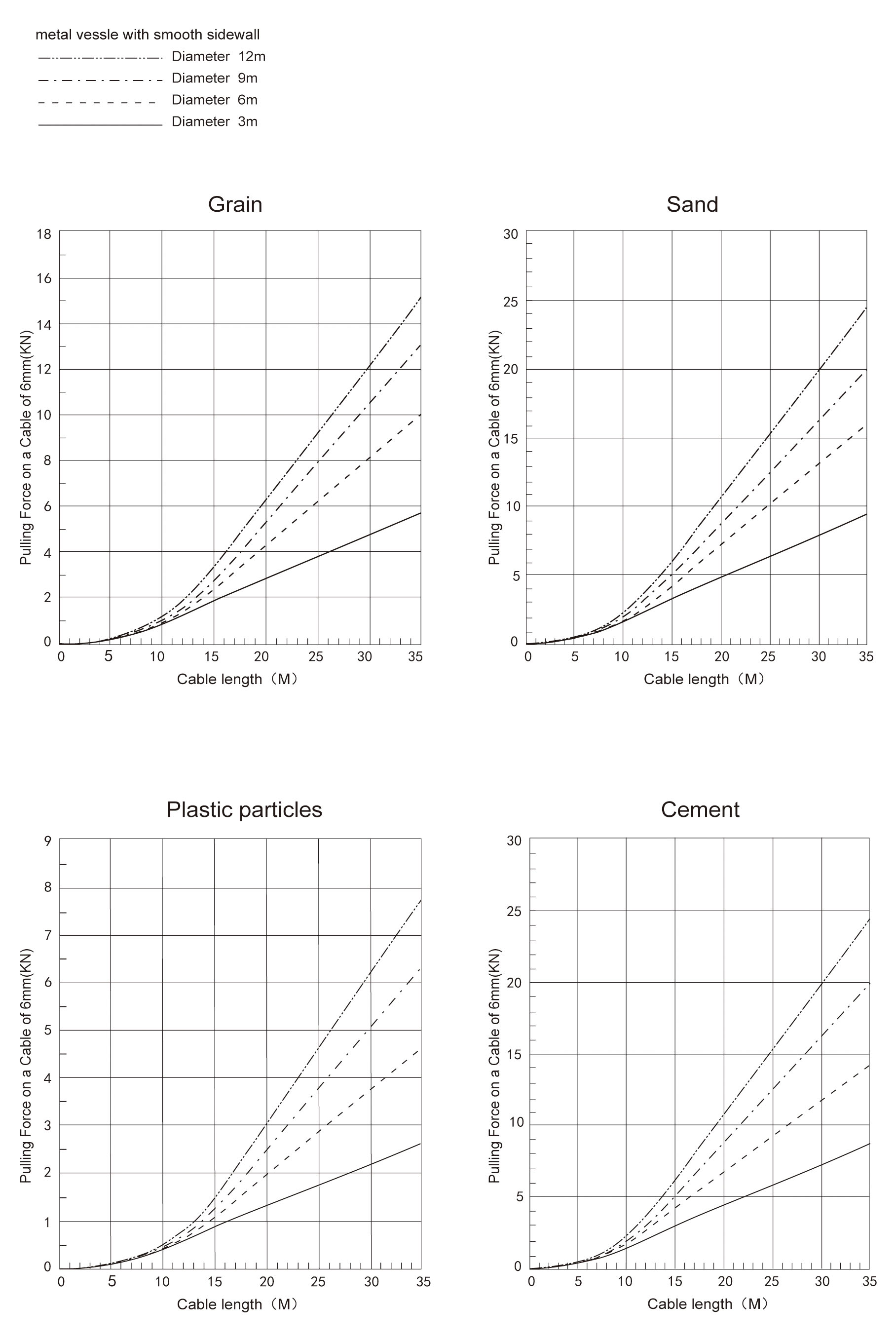
Pull down force on the rope
When feeding and discharging, the medium produces a pull-down force on the cable probe. The pull-down force depends on the following factors:
A. The length of the rope B. The density of the material
C. The diameter of the storage bin D. The diameter of the rope
Optimization of interference
Interference echo suppression: Programming and debugging software can realize the suppression of interference echo, so as to achieve the ideal measurement effect.
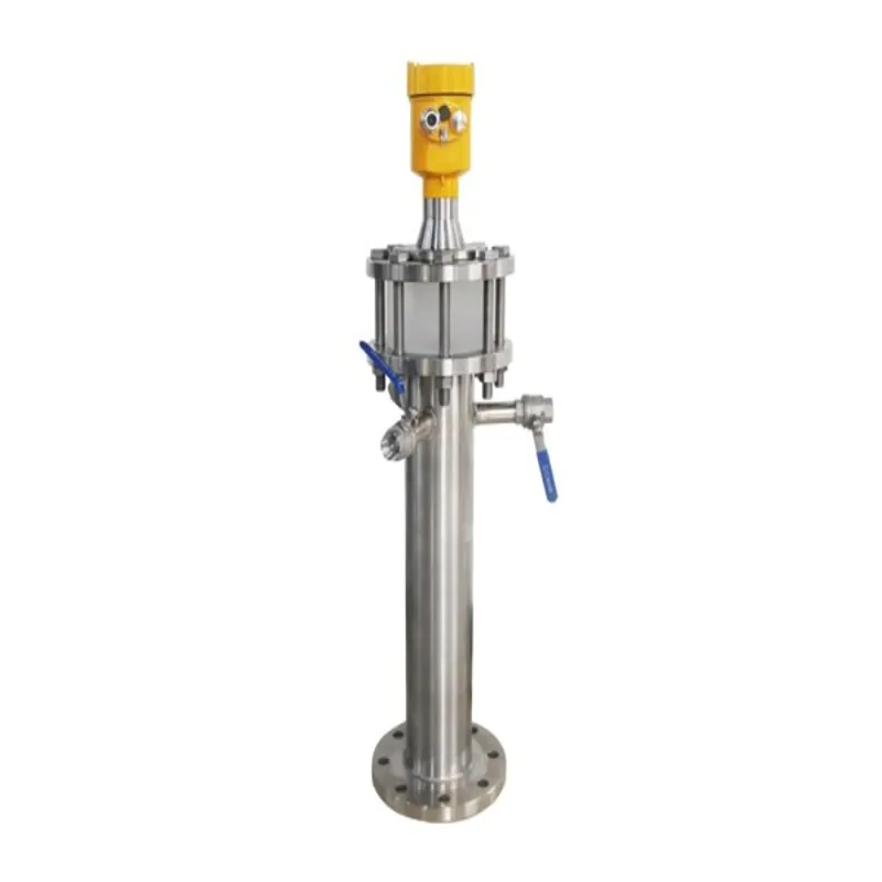
For media with a viscosity not greater than 500cst (only for liquids), bypass pipes or guided wave-pipe can be used to avoid interference.
Installation of low dielectric constant liquid
For media with dielectric constant greater than 1.3, viscosity ≤ 500cst and not easy to produce adhesion, the guided wave-pipe can be installed for measurement, and the following effects can be achieved:Installation and fixation with the same measurement of solid powder compartment.
Excellent reliability, high precision
It can be used for any medium with a dielectric constant ≥1.3, and the measurement has nothing to do with the conductivity of the medium
Obstacles in the tank and the size of the short pipe do not affect the measurement
Corrosive medium measurement:
If measuring corrosive media, you can use rod or cable probe sleeve PTFE, PFA sleeve for measurement.
Special instructions and precautions:
Ø For guided wave radars with too long cables in field use, it is necessary to cut off the excess cables, and the cables cannot be knotted, entangled or attached to other objects.
Ø When cutting the cable, first cut off the power of the instrument, remove the cable, remove the screws, cut from the bottom of the cable, and install the weight after the cut is completed, and then the power can be switched on and the parameters can be reset.
Ø For cable guided wave radar with protective sleeve, when the cable is too long, it must not be intercepted by itself, and it must be returned to the original factory for cutting.
Ø For the instrument installed in the still-pipe, the radar probe must be fixed with an insulating bracket to ensure that the radar probe (rod/cable) and the still-pipe are concentric, otherwise the measurement will be affected by vibration or false echo.

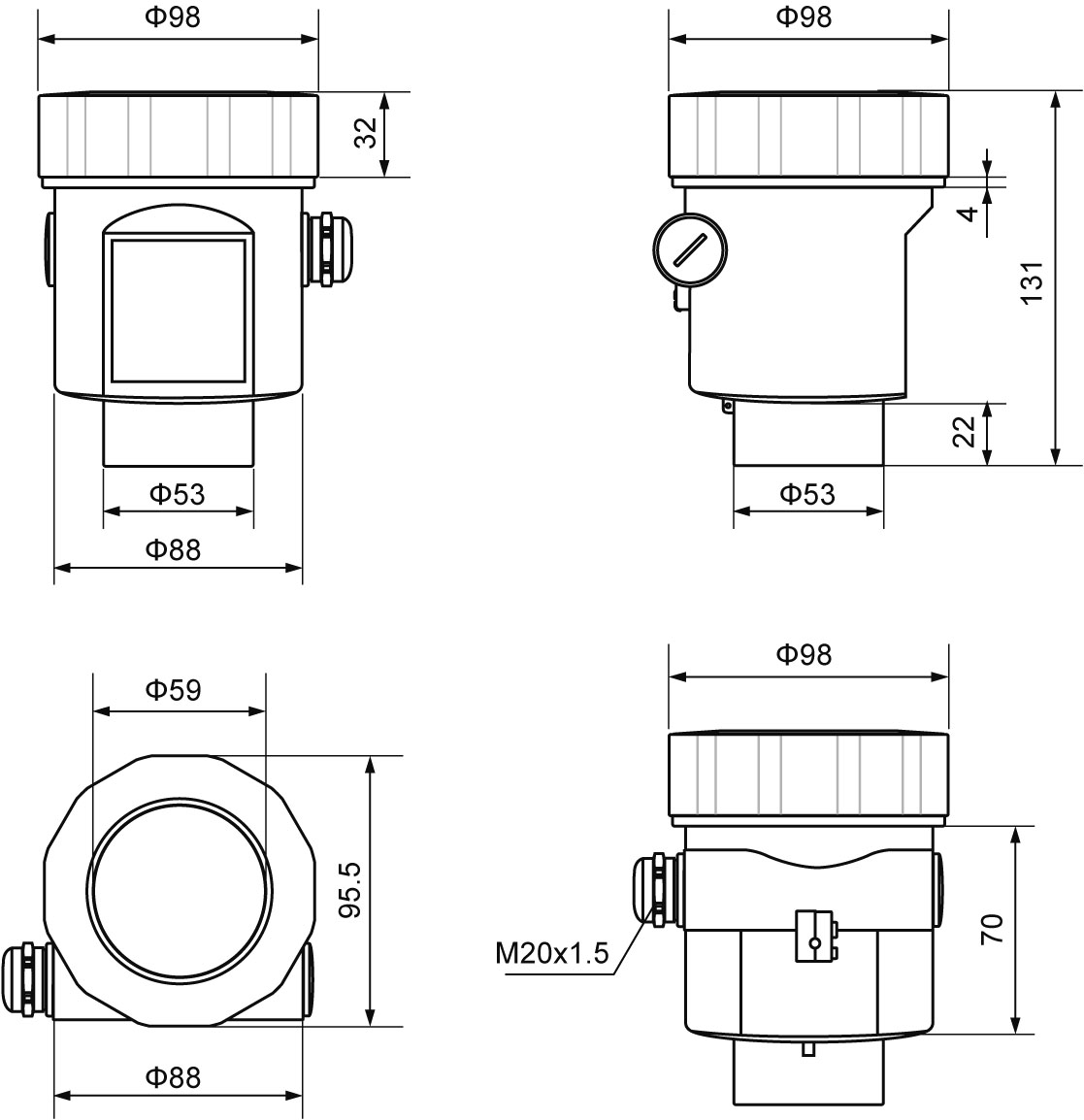
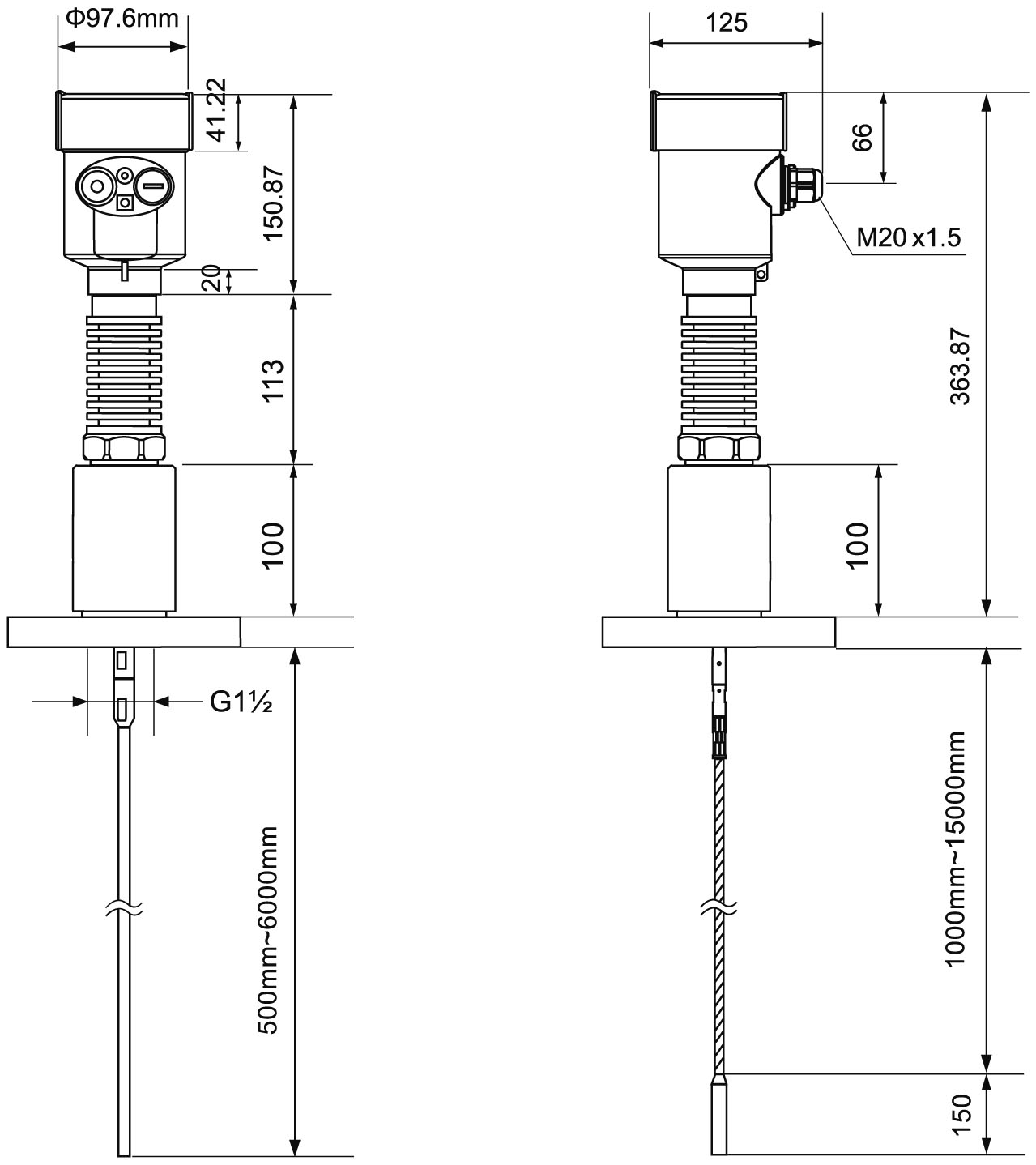
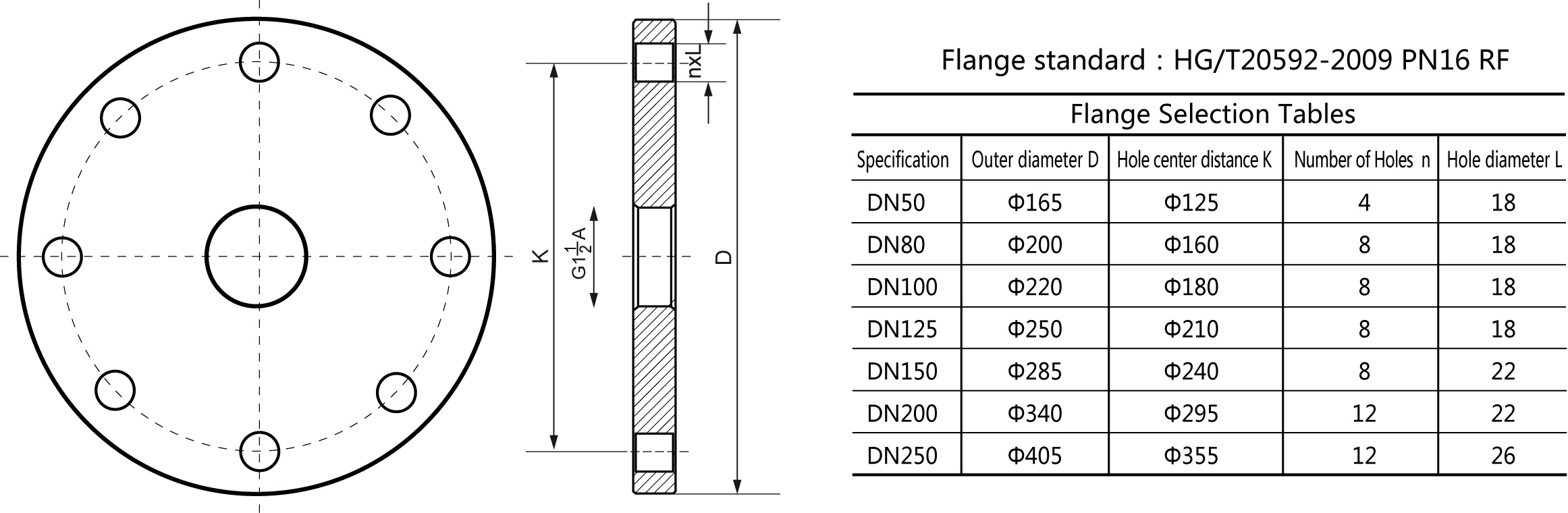
Structure Size(Unit: mm)
Outer Case size
Ø Cast aluminum shell
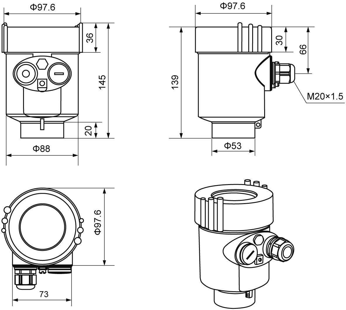
Ø Plastic shell
Product size
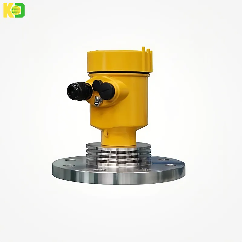
Flange type
The Electrical Connection
| |
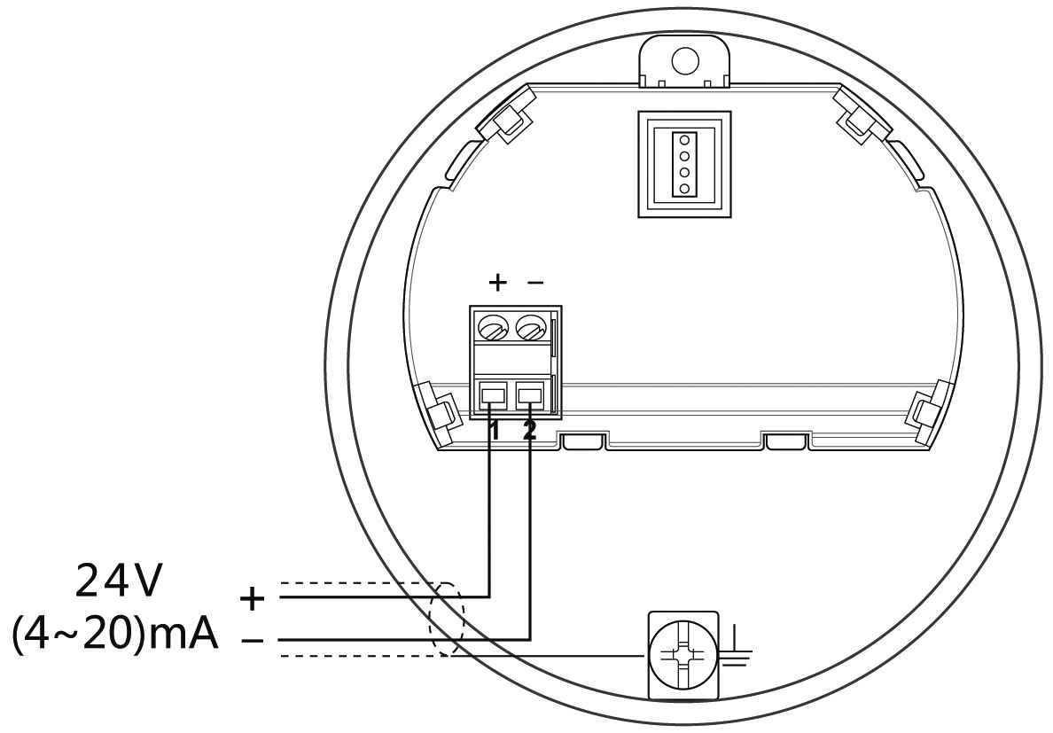
(4~20)mA /HART (Two wire system) | The power supply and the output current signal sharing a two core shield cable. The supply voltage range see technical data. For intrinsically safe type must be a safety barrier between the power supply and the instrument. |
(4~20)mA/HART(Four wire system) | Separate power supply and the current signal, respectively using a two-core shielded cable. The supply voltage range see technical data. |
Modbus-RS485(Four wire system) | Power supply and Modbus signal line separated respectively using a two-core shielded cable, the power supply voltage range see technical data. |
| |
General Introduction | Supply cable can use ordinary two-core cable, the cable diameter should be (6~12) mm, to ensure that the cable entry seal. If electromagnetic interference exists, recommended to use shielded cable. |
(4~20) mA/HART(Two-wire) | Supply cable can use ordinary two-core cable. |
(4~20) mA/HART(Four-wire) | Supply cable should be used with a dedicated ground cable. |
Modbus-RS485(Four-wire) | Shielded cable should be used for the power supply cable. |
Shielding and wiring | Both ends of the shielded cable should be grounded. Inside the sensor, the shield must be connected to the internal ground terminal. The external ground terminal on the enclosure must be connected to the ground. If there is ground current, the shielded cable must be grounded through a ceramic capacitor (for example: 1nF/1500V) far away from the shielding end of the instrument side to block direct and bypass high-frequency interference signals. |
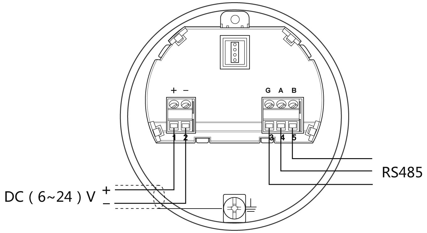
Wiring Diagram
Ø 24V two wire wiring diagram as follows:
Ø 6~24V Modbus-RS485 wiring diagram as follows:
Explosion Proof Connection
The intrinsic safety version sensors (Exia Ⅱc T6) use Alu-die casting housing and filling Silicone rubber sealants internal structure aimed to prevent sparks resulted from circuit failure from leaking out. It is applicable for the continuous level measurement of flammable medium under Exia Ⅱc T6.
A safety barrier FBS-2 must be used together with the intrinsic safety instrument. It is an associated device to this product for the power supply of this product. The main specification is intrinsic safety: Exia ⅡC, voltage of power supply: 24V DC±5%, short-circuit current: 135mA, operating current: 4...20mA.
All cables must be shielded. The max length is 500m for the cable from the barrier to the sensor. Stray capacitor≤0.1μF/Km, stray inductance 1mH/Km. Instrument must be connected to the ground potential. Any unapproved associated device is not allowed to be used.
Safety instructions:
Ø Please observe the local electrical code requirements!
Ø Please comply with local requirements for personnel health and safety regulations.
All electrical components of instrument operation must be completed by the formal training of professionals.
Ø Please check the instrument nameplate to provide product specifications meet your requirements. Please make sure that the power supply voltage and instrument nameplate on the requirements.
Protection Grade:
 The instrument fully meet the requirements of protection class IP66/67, make sure the
cable head waterproof seal. As shown below:
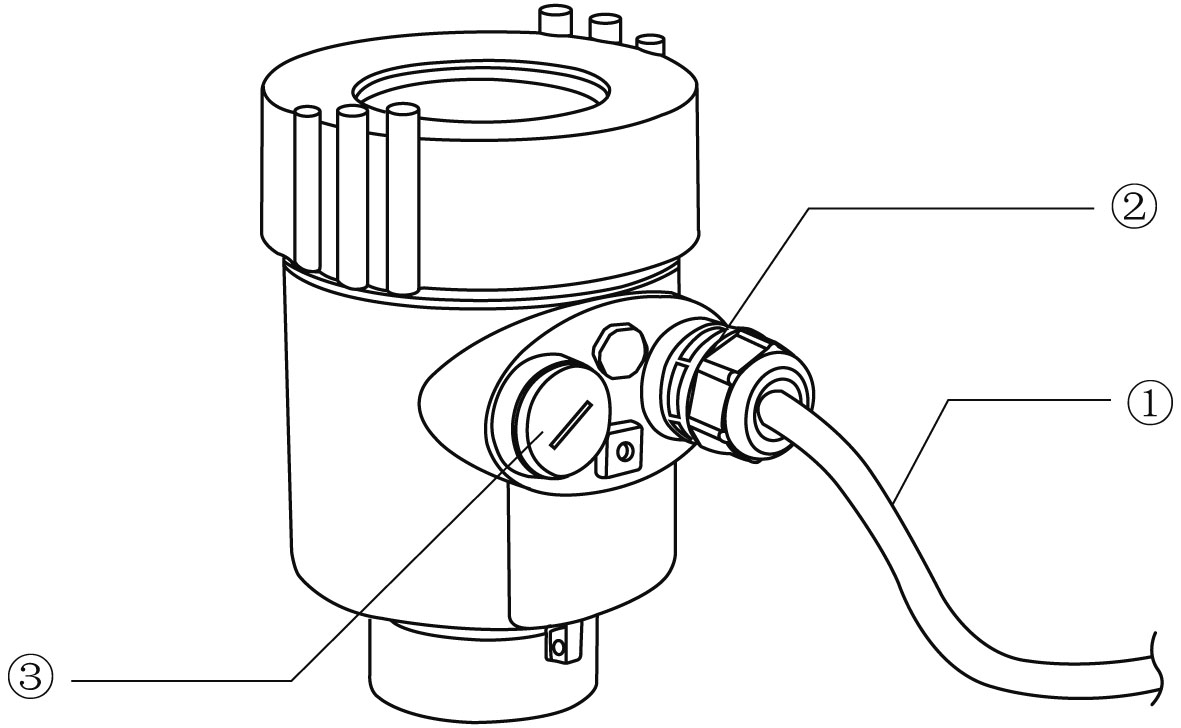
How to ensure that the installation meets IP67 requirements:
Make sure that the sealing head is not damaged.
Make sure that the cable is not damaged.
Make sure the cable is used in line with the electrical connection specifications.
Before entering the electrical interface, bend the cable down to ensure that the water
does not flow into the housing, see ①
Please tighten the cable sealing head, see ②
Keep electrical interface with blind unused block after block tight, see ③
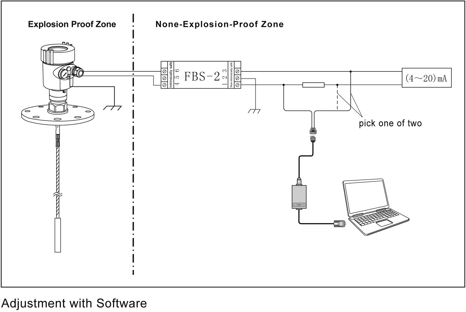
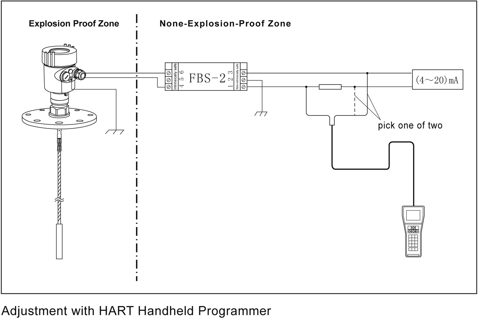
Instrument debugging
Three kinds of debugging method:
1) Display / Button (With split display, you need to debug on the split)
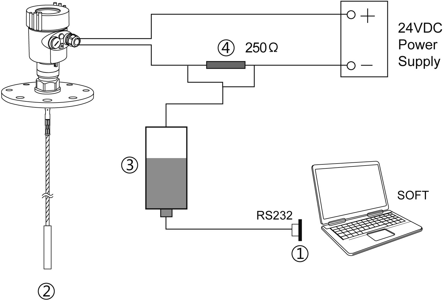
2) Debug through computer software
3) HART Handheld programmer
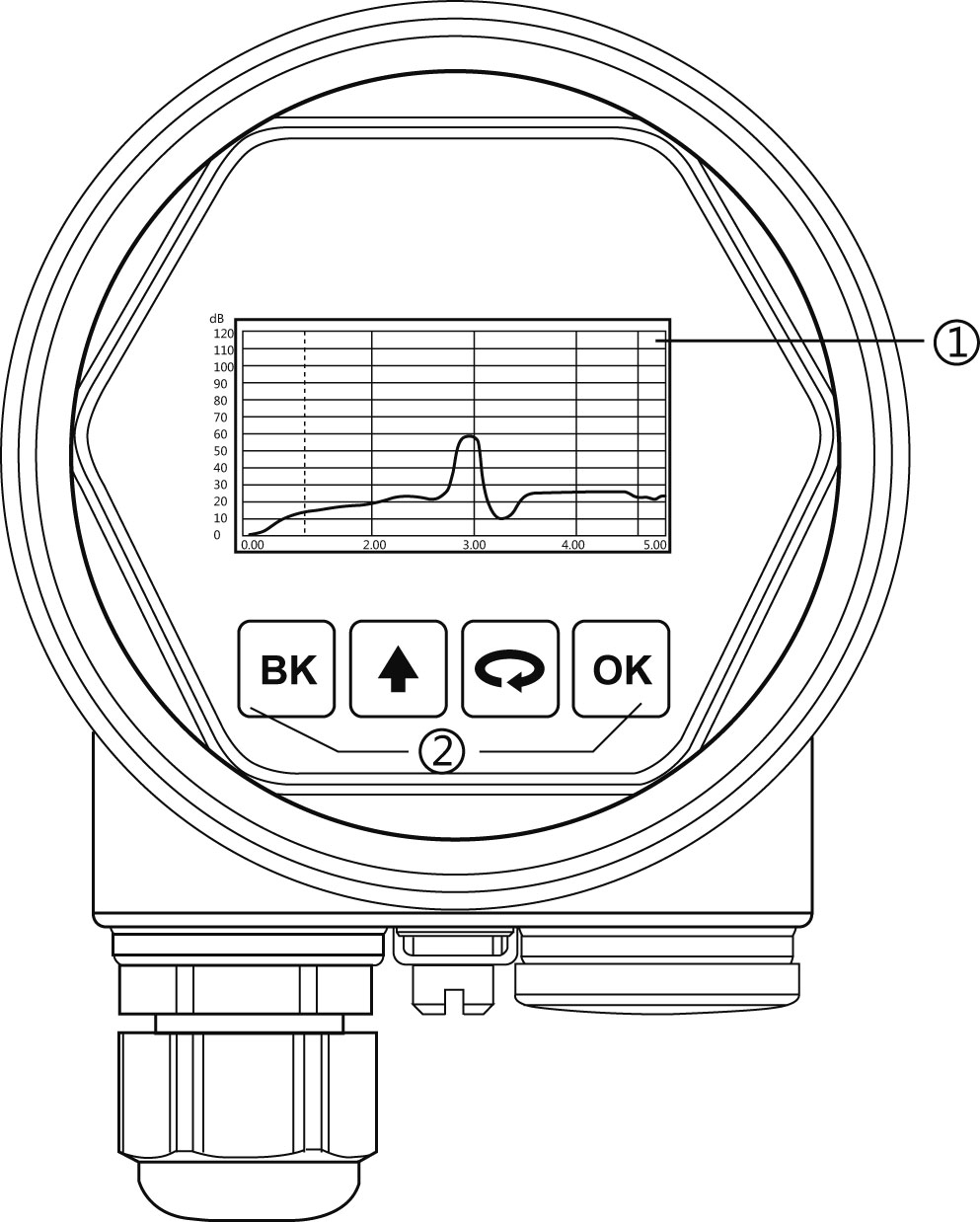
Display / Button:
Debug the meter through the 4 buttons on the display screen. The debugging menu has four languages to choose from. The measured value can be read very clearly through the glass window.
Technical Specification
General Parameters | |
Probe Material: | |
Rod | Stainless Steel 304,316L / PTFE / PFA |
Cable | Stainless Steel 304,316L / PTFE |
Process Connection | Thread G1½″A , Thread 1½″ NPT / Flange / Clamp |
Seal | Viton fluorine rubber, Kalrez fluorine rubber |
Outer casing | Aluminum,Plastic,Stainless Steel |
Seal between the outer casing and the cover | Silicone Rubber |
View Point Window | Polycarbonat |
Ground Terminal | Stainless Steel 316L |
Power Supply | |
2-Wire system | 24V DC |
4-Wire system | 6~24V DC (Modbus-RS485) 198 ~242V AC (Flameproof Type / Double cavity) 110V AC (Flameproof Type / Double cavity) |
Power Consumption | max. 22.5mA |
Ripple Allowed | - <100Hz Uss < lV - (100~100K)Hz Uss < l0mV |
Cable parameters | |
Cable Entry / Plug | One cable entry of M20×l.5 (cable diameter of 6~12mm) One blind stopper M20×l.5 |
Spring Connection Terminal | Applicable for cables with cross section of 2.5mm |
Output parameters | |
Output Signal | (4~20)mA HART / Modbus-RS485 |
Resolution | 1.6μA |
Fault signal | Current output is unchanged; 20.5mA;22mA;3.9mA |
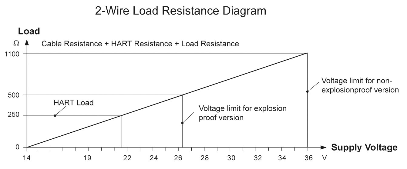
2-wire load resistance | See the diagram below |
4-wire load resistance | Max 500Ω |
Integration Time | ( 0~36)sec, adjustable |
 | |
| Characteristic Parameters | |
Max Measurement Distance | 15m /6m(Cable /Rod) |
Measurement Interval | About 1sec (Depend on parameter settings) |
Adjustment Time | About 1sec (Depend on parameter settings) |
Resolution of Display | 1mm |
Accuracy | ±5mm |
Accuracy diagram
| |
Temperature for Storage/Transport | (-40~80) ℃ |
Process Temperature (Antenna part) | (-40~120)℃ Standard type (-40~200)℃ High temperature type |
Relative Humidity | <95% |
Pressure | Max. 4.0MPa |
Vibration Proof | Vibration frequency (10~150) Hz, maximum vibration acceleration l0m/s² |
Max Pulling Force | See the illustrative diagram on pulling force |
When measuring solid medium, the pulling force is determined by the diameter of vessel and medium level, some examples of pulling force generated by typical medium are shown on the diagrams below. | |
 | |
Product Model Selection
705
Maximum Range / Type of detecting component |
15000mm / Single cable type or 6000mm/ single rod type |
Explosion Proof Approval |
P Standard (Without Approval) I Intrinsically Safe(Exia IIC T6 Ga) G Flameproof (Exd IIC T6 Gb) |
Type of detecting component /Material |
A Cable Φ8mm / Stainless Steel 304 B Cable Φ4mm / Stainless Steel 316L C Rod Φ12mm / Stainless Steel 304 D Rod Φ12mm / Stainless Steel 316L |
Process Connection /Material |
G Thread G1½″ A N Thread 1½″ NPT C Flange DN50 PN16 / Stainless Steel D Flange DN80 PN16 / Stainless Steel E Flange DN100 PN16 / Stainless Steel F Flange DN150 PN16 / Stainless Steel H Flange DN200 PN16 / Stainless Steel I Flange 2〞150LBS ANSI Convex / Stainless Steel 316L J Flange 3〞150LBS ANSI Convex / Stainless Steel 316L K Flange 4〞150LBS ANSI Convex / Stainless Steel 316L L Flange 6〞150LBS ANSI Convex / Stainless Steel 316L M Flange 8〞150LBS ANSI Convex / Stainless Steel 316L |
Seal / Process Temperature |
1. Normal (-200~400)℃ |
The Electronic Unit |
3 (4~20) mA / 24V DC / HART two wire system 4 (4~20) mA / 220V AC / HART four wire system 5 RS485 Modbus / 6~24V four wire system |
Outer Covering / Protection Class |
L Aluminum / Single cavity / IP67 H Aluminum / Double cavity / IP67 G Plastic / Single cavity / IP65 K Stainless steel / Single cavity / IP67 |
Cable Line |
M M 20 × 1.5 N ½″ NPT |
Display / Programming |
A With X Without |
We are here to help you! If you close the chatbox, you will automatically receive a response from us via email. Please be sure to leave your contact details so that we can better assist


![kaidi KD-906 26G Radar Level Meter [Anti-corrosion] High Temperature Intelligent](https://img80003270.weyesimg.com/uploads/kaidi86.com/images/16760218661446.jpg?imageView2/2/w/1920/q/80/format/webp)


![kaidi KD-802 6G Radar Level Meter [Anti-corrosion Type]](https://img80003270.weyesimg.com/uploads/kaidi86.com/images/15936739299092.jpg?imageView2/2/w/1920/q/80/format/webp)
![kaidi KD-FMF15 FM radar level meter [chemical and electric power industry]](https://img80003270.weyesimg.com/uploads/kaidi86.com/images/15936722293812.jpg?imageView2/2/w/1920/q/80/format/webp)