Español
  pусский
  العربية
  Português
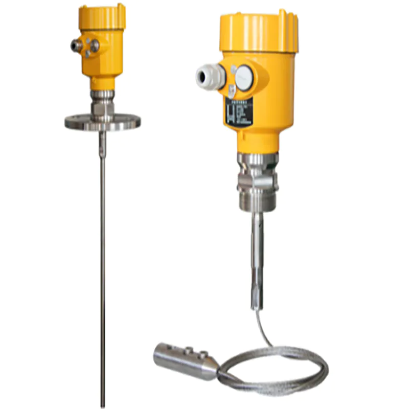
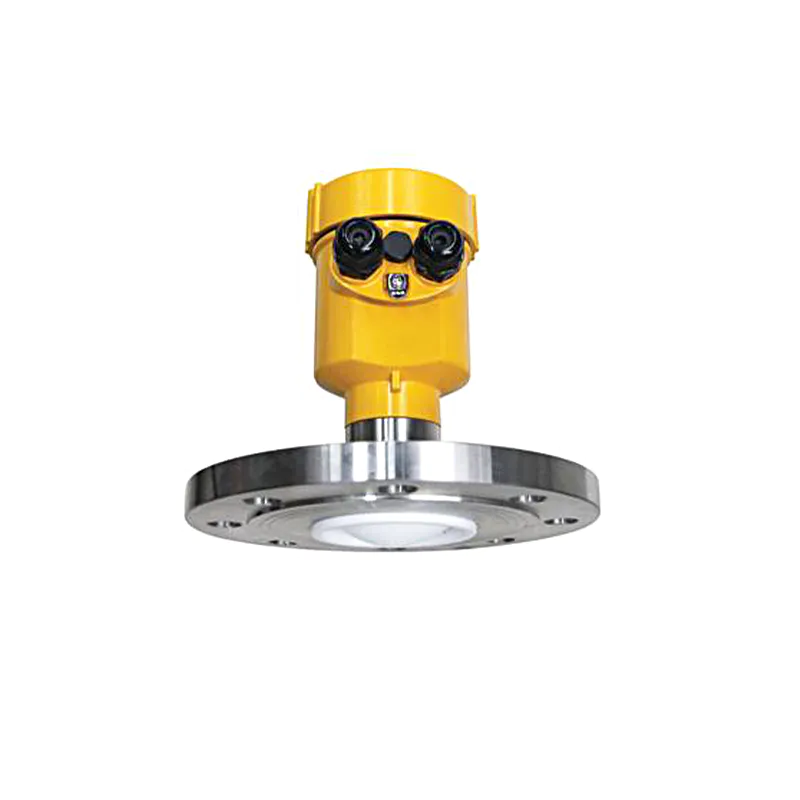
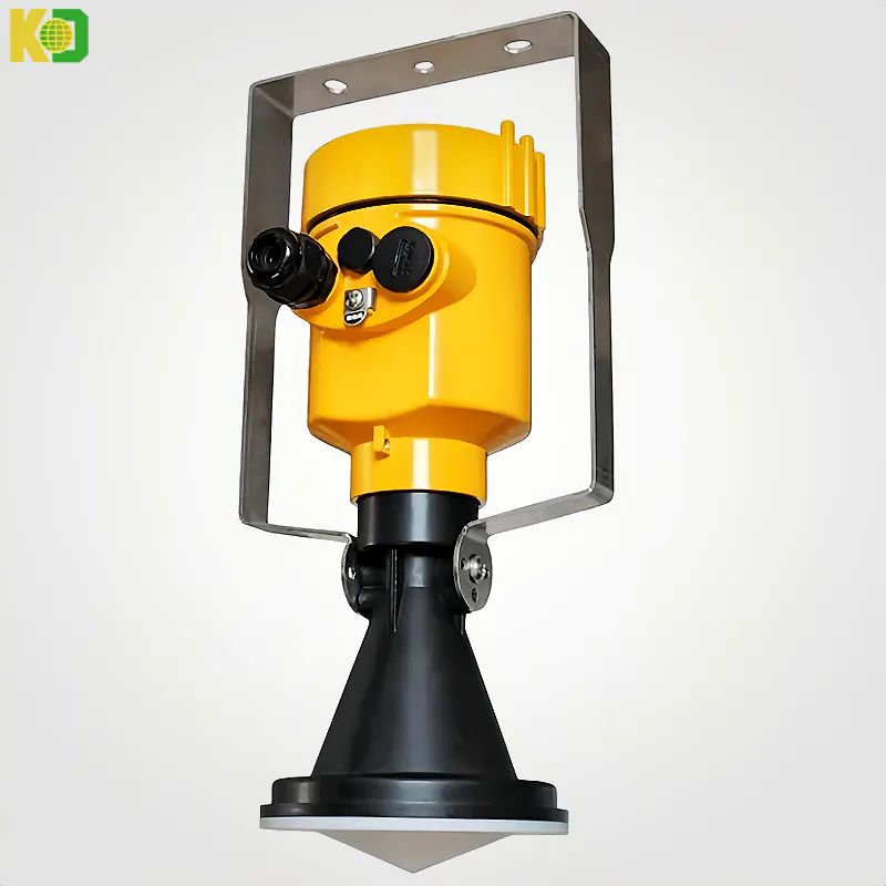
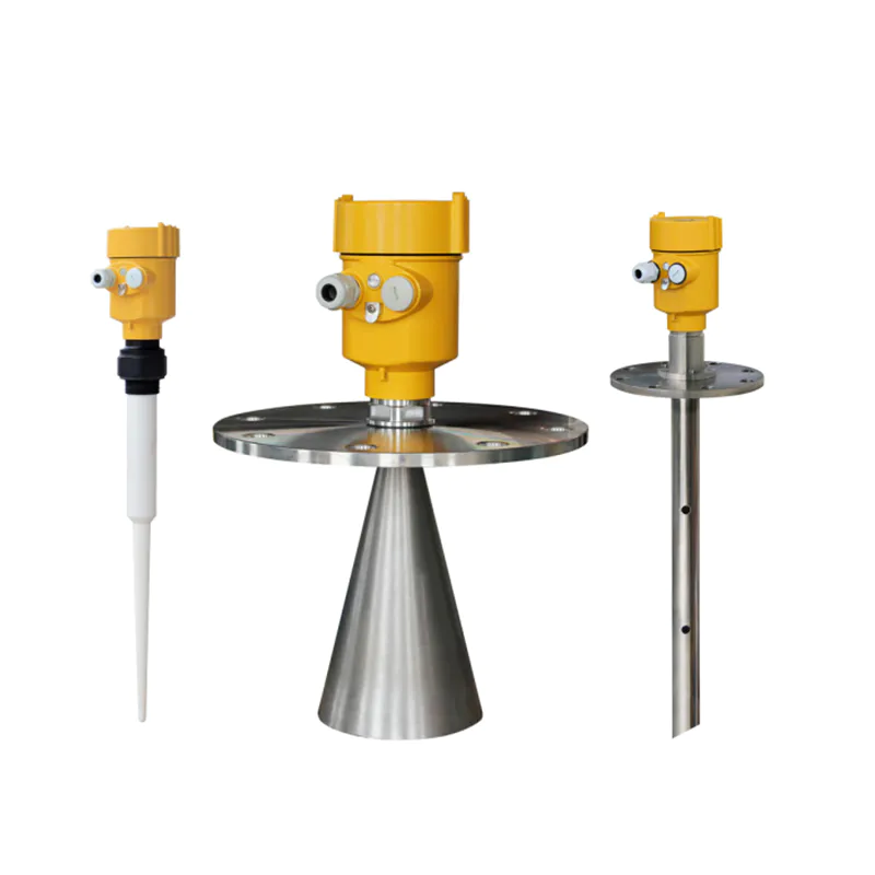
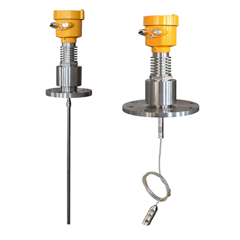
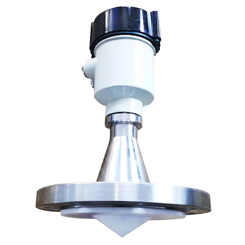
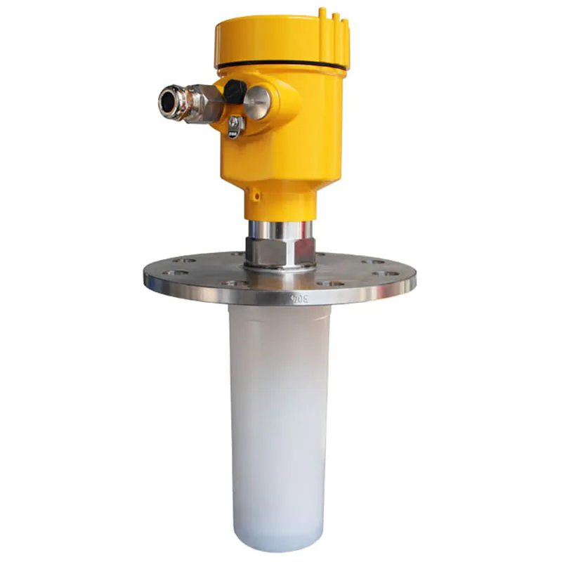
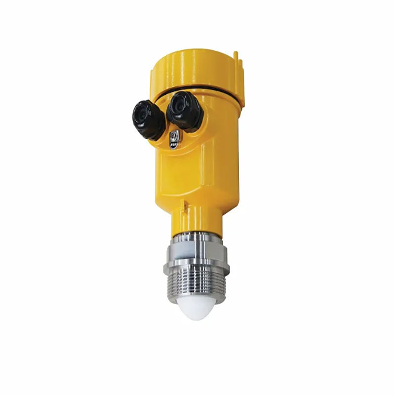
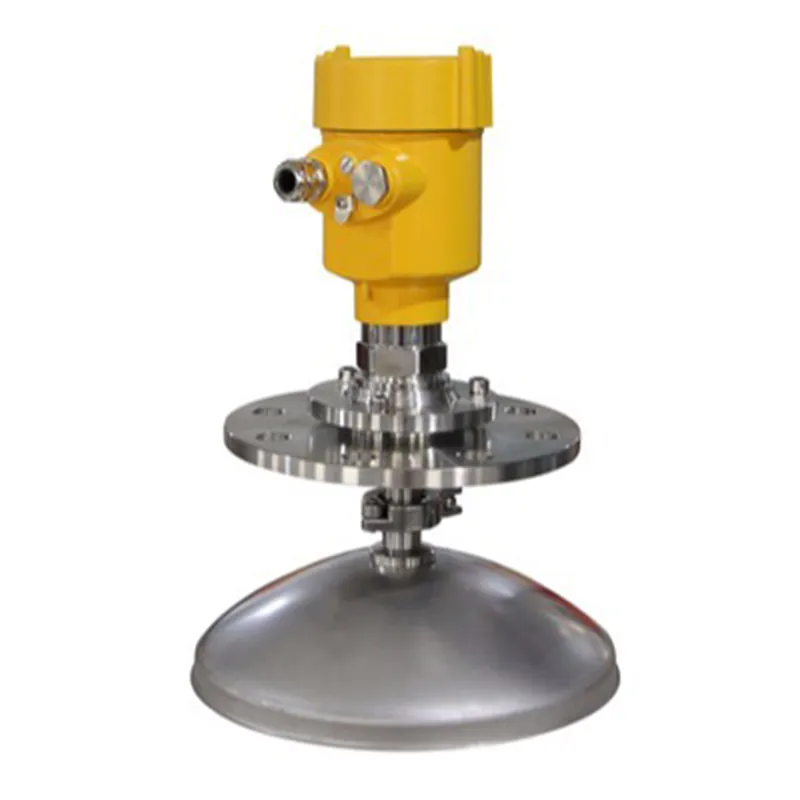
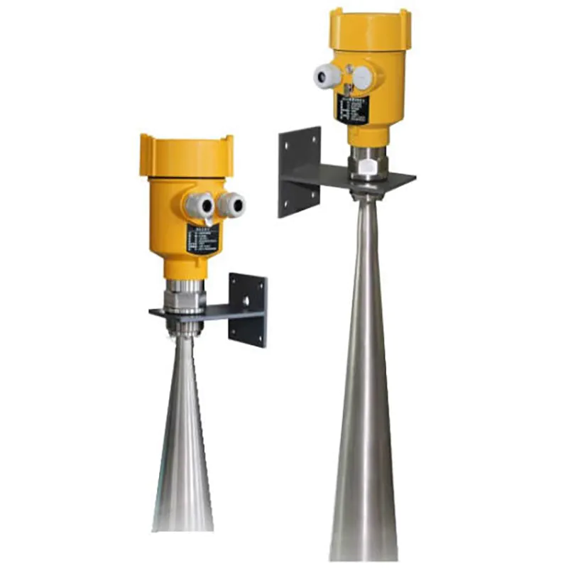
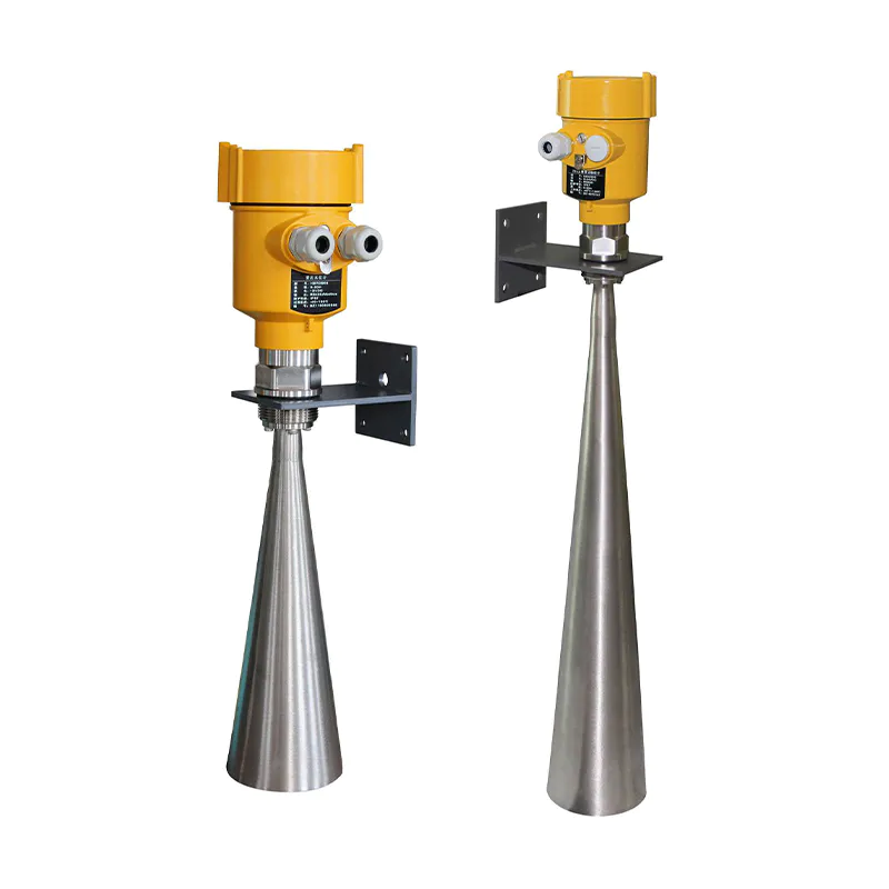
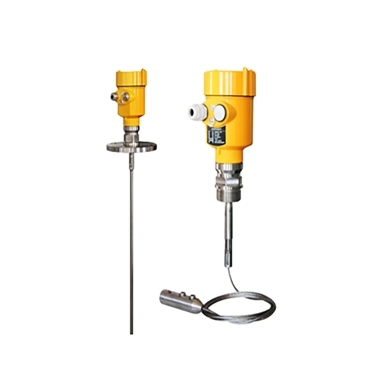
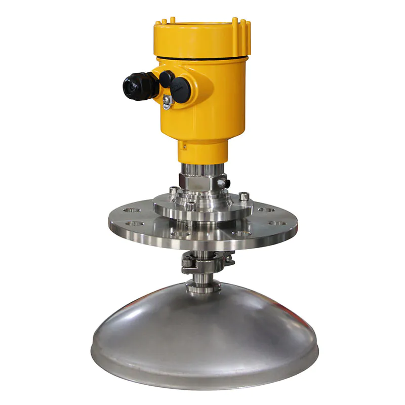
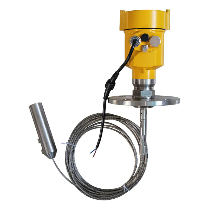
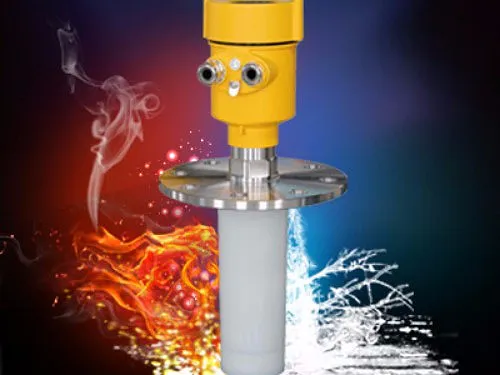
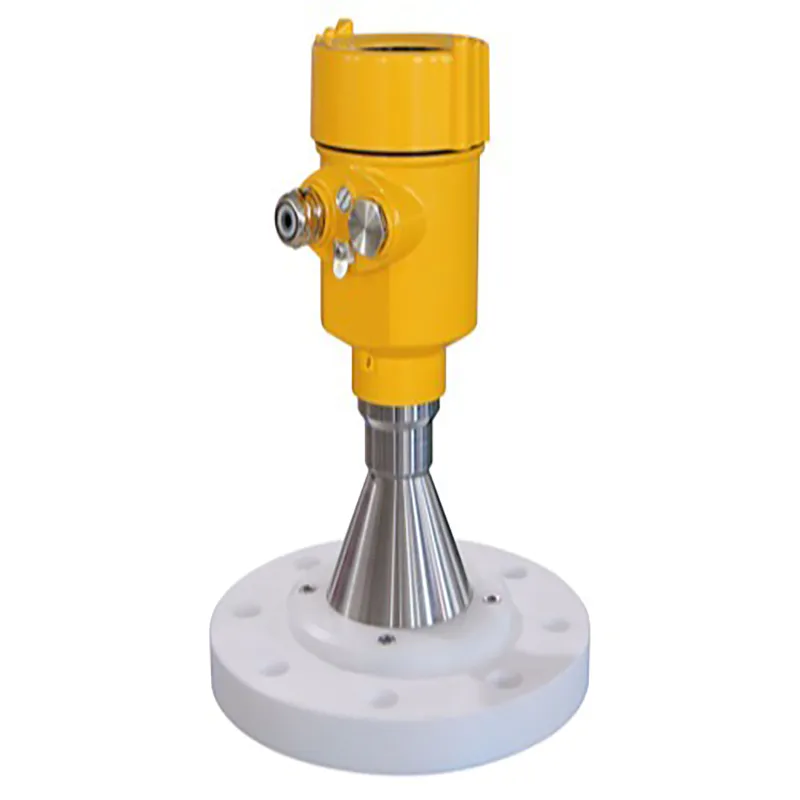
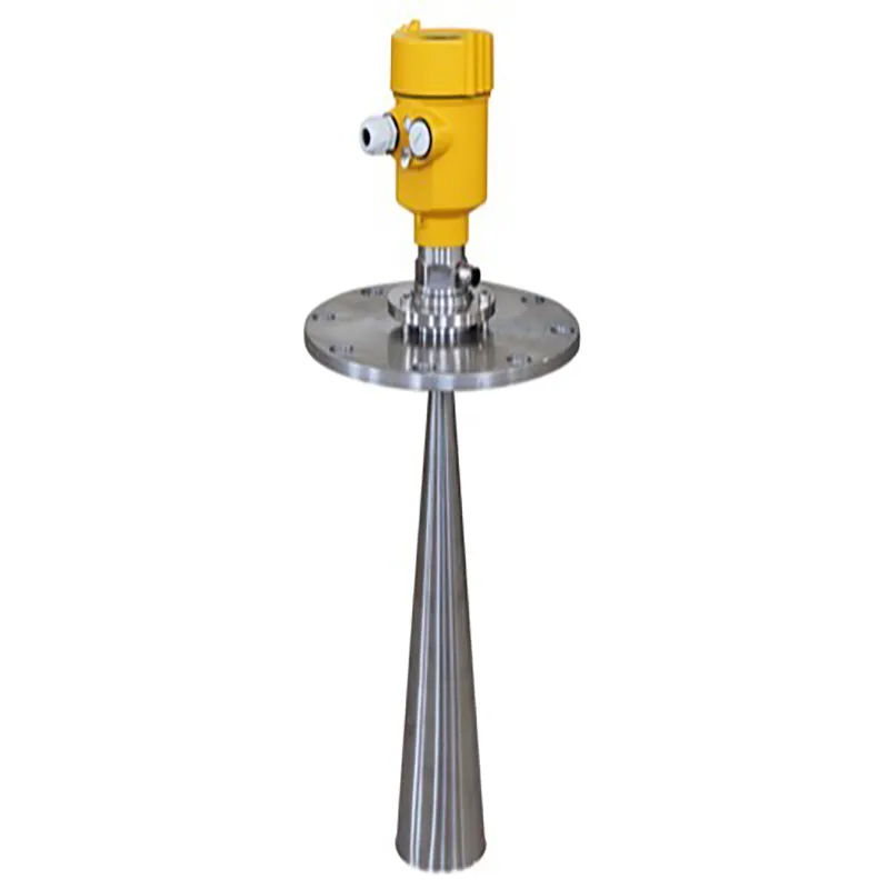
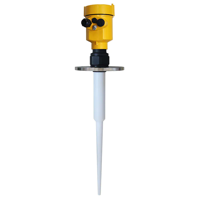
Radar Level Meter 80G FM Radar Type Level Measuring Instrument Kaidi KD-FMW21S FM
KDRD-FMW Series Sensor Is 80G FM Radar Type Level Measuring Instrument, Measuring Distance Up To 150 Meters
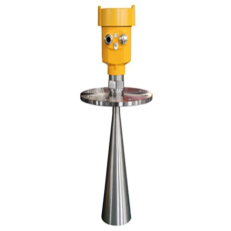
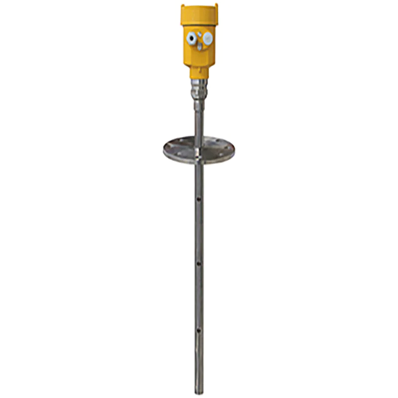
KD-90X series sensors are 26G high frequency radar type level measuring instruments with measuring distance up to 80 meters. The antenna is further optimized and the new fast microprocessor allows for higher speed signal analysis and processing, making the meter available for measurement of a variety of highly corrosive liquids.
The radar level antenna emits narrow microwave pulses, which are transmitted downward by the antenna. Microwave contact with the measured medium surface is reflected back again by the antenna system, the signal will be transmitted to the electronic circuit part automatically converted into a level signal (because the microwave propagation speed is very fast, electromagnetic waves to reach the target and return to the receiver by the reflection of the time used in this round trip is almost instantaneous).
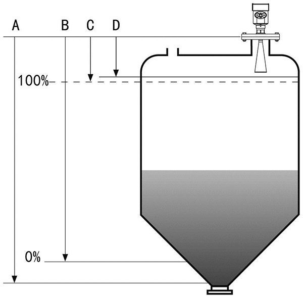
A: range setting, B: low level adjustment, C: high level adjustment, D: blind range
The reference surface for measurement is: the bottom surface of the thread or the sealing surface of the flange.
Note: When using the radar level meter, make sure that the highest material level cannot enter the measurement blind zone (the area shown in D in the figure).
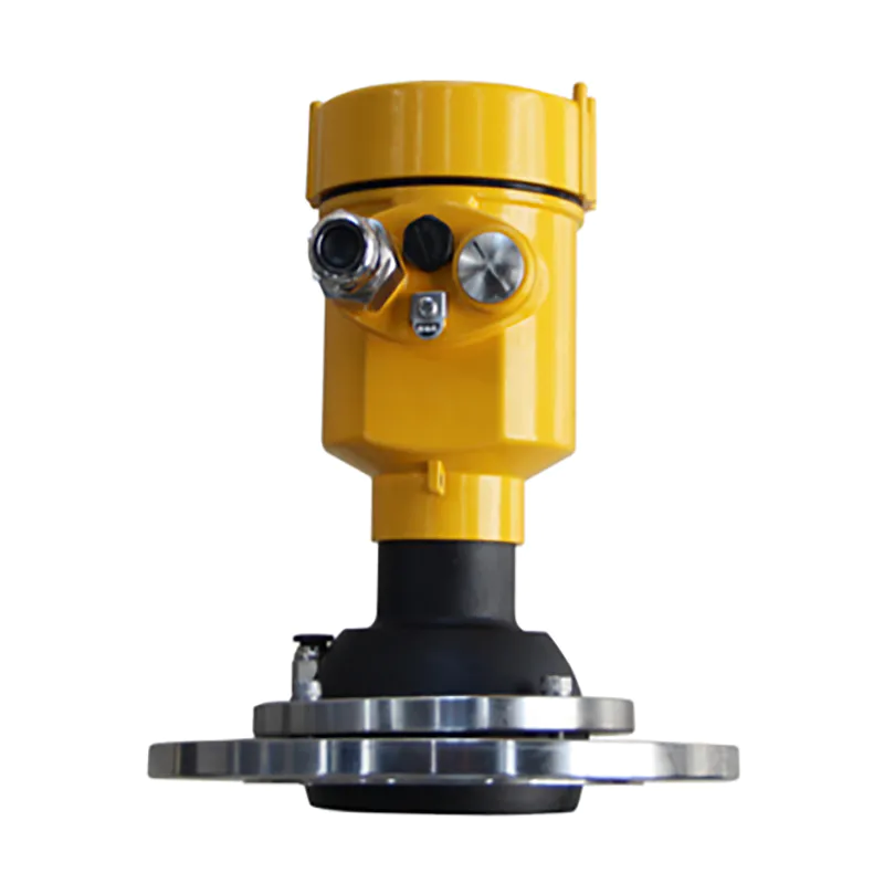
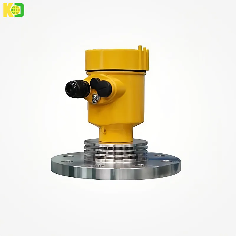
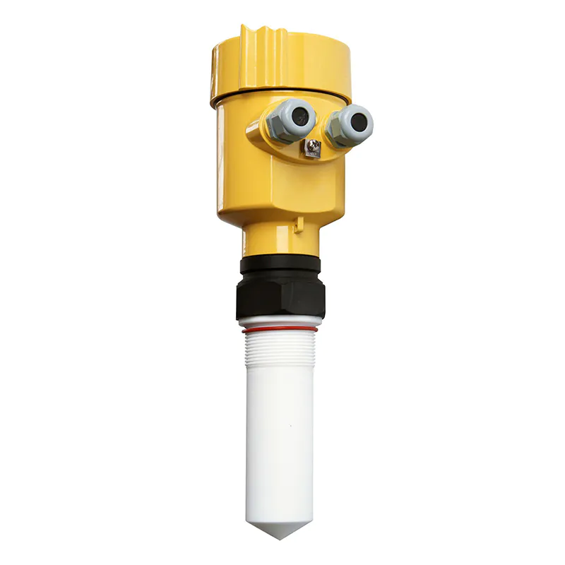
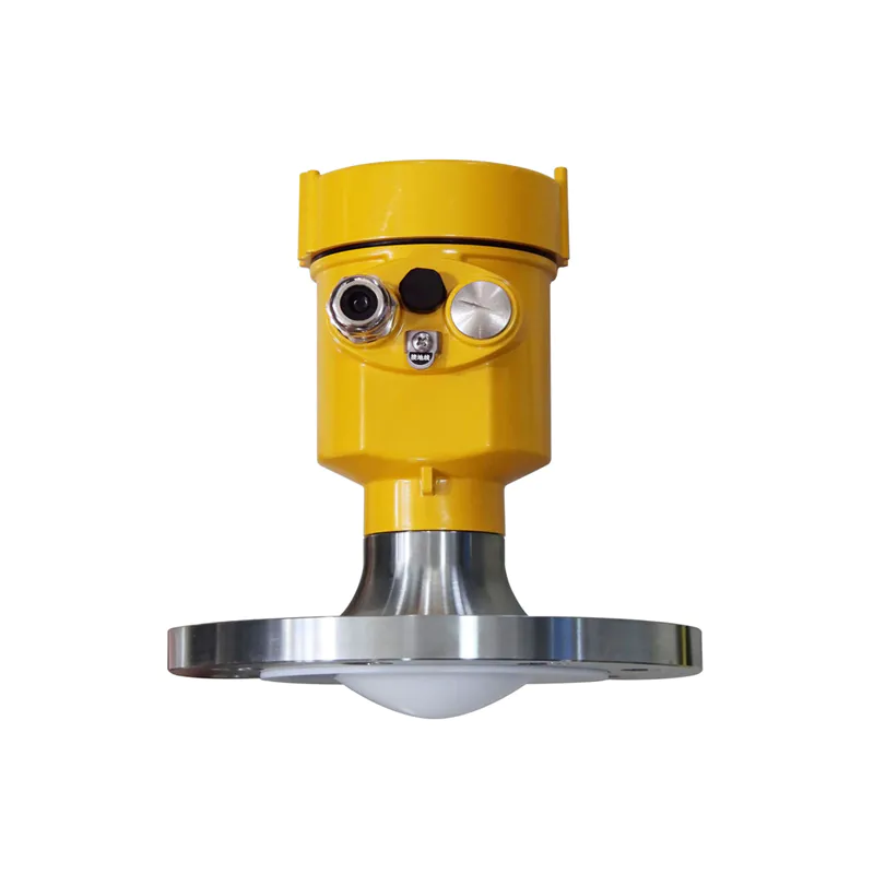
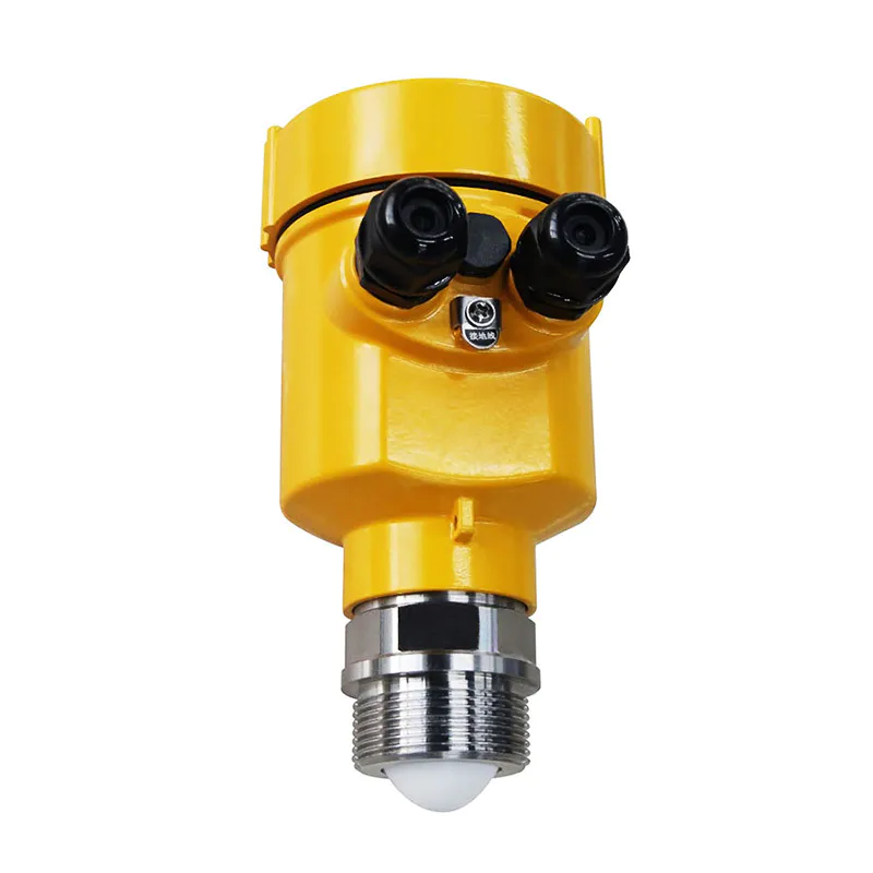
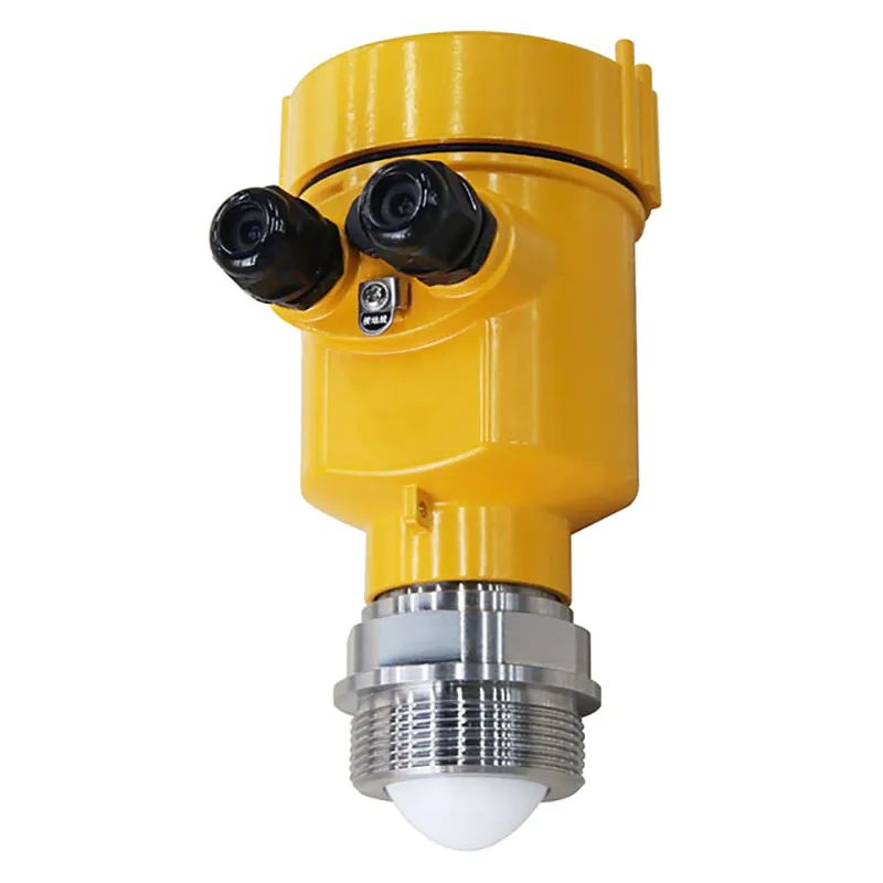
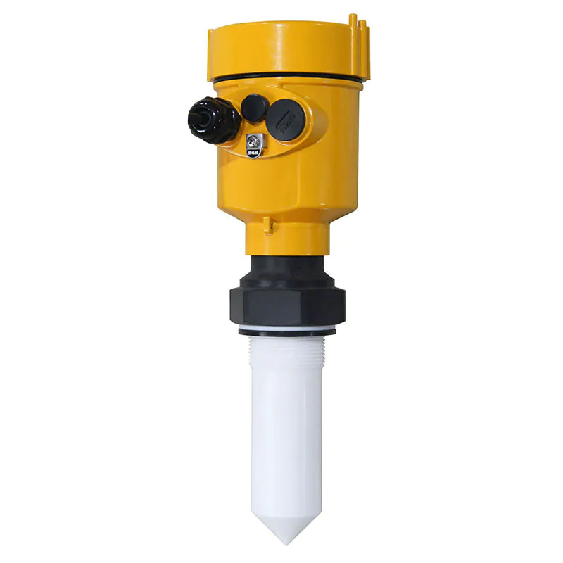
 ● Small antenna size for easy installation; non-contact radar, no wear and tear, no contamination.
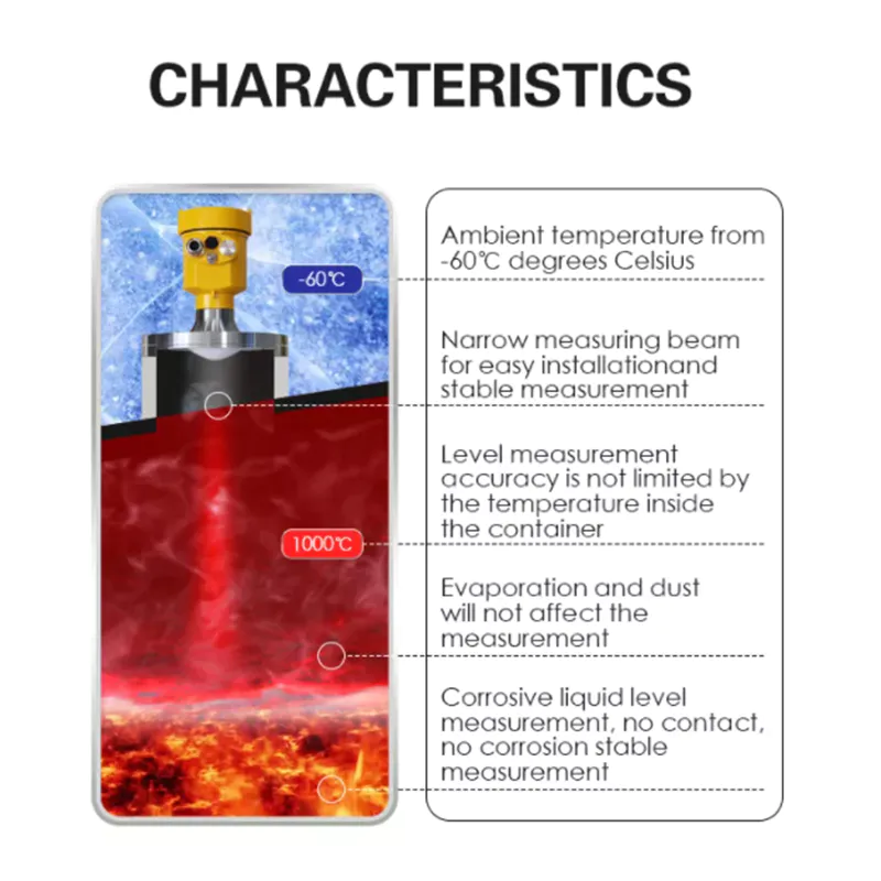
● Virtually unaffected by corrosion, foam; virtually unaffected by water vapor, temperature and
pressure changes in the atmosphere.
● Severe dusty environment has little effect on the work of high frequency level meter.
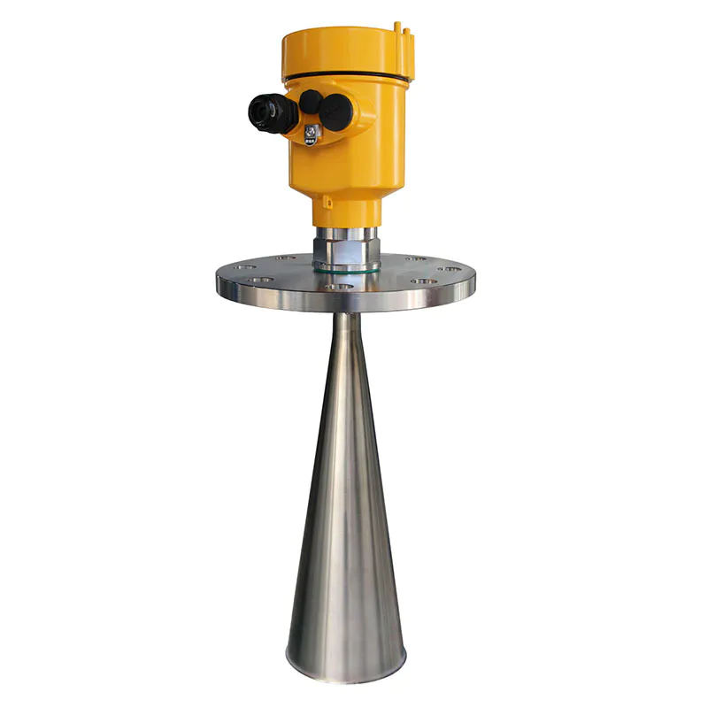
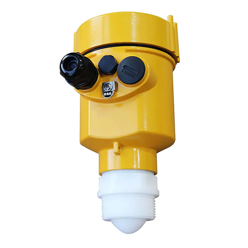
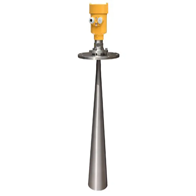
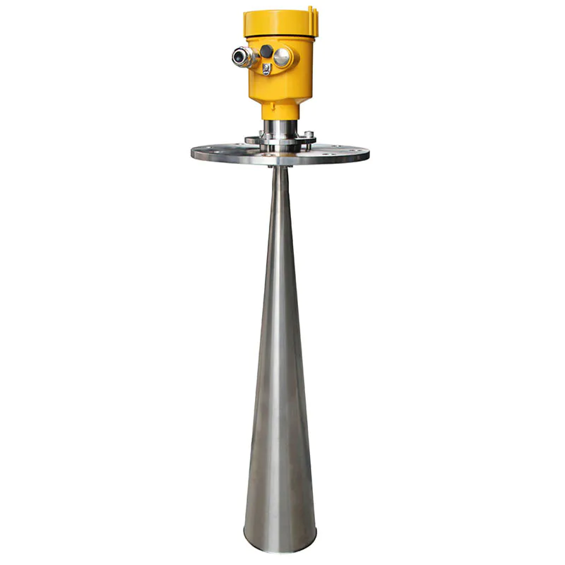
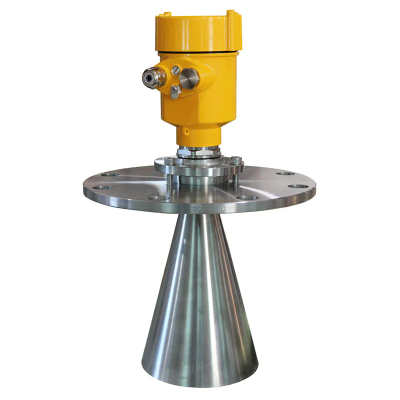
● Shorter wavelength, better reflection on inclined solid surfaces.
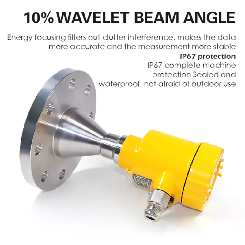
● Smaller beam angle and concentrated energy, which enhances the return capability and helps to
avoid interfering objects at the same time.
● Smaller measurement blind spot, and good results for small tank measurements.
● High signal-to-noise ratio for better performance even under fluctuating conditions.
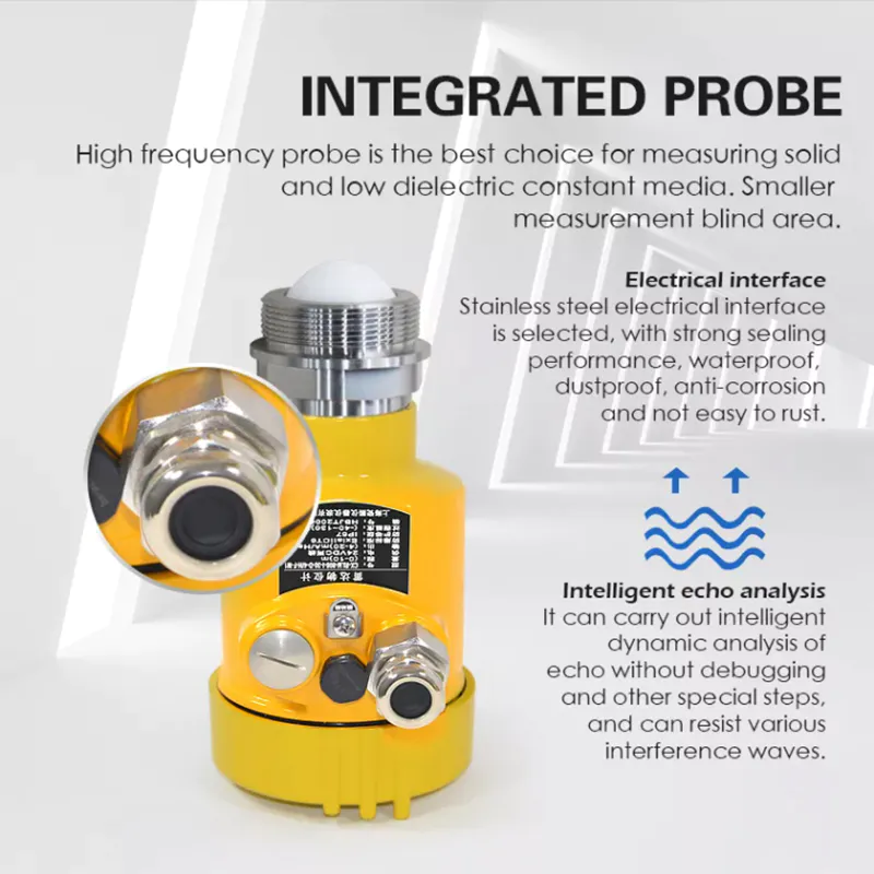
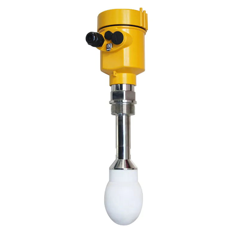
● High frequency, a better choice for measuring solids and low dielectric constant media.
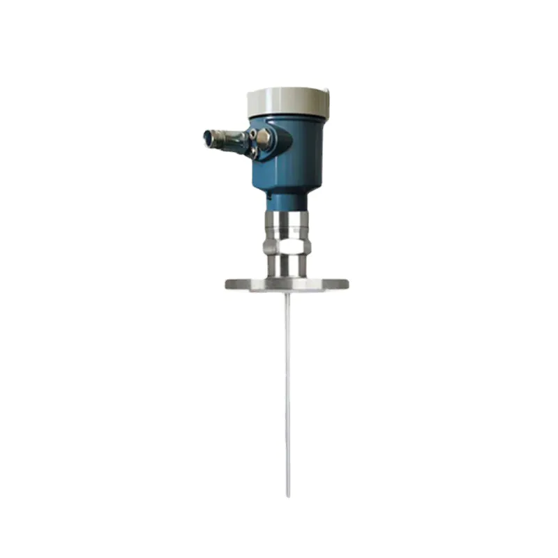
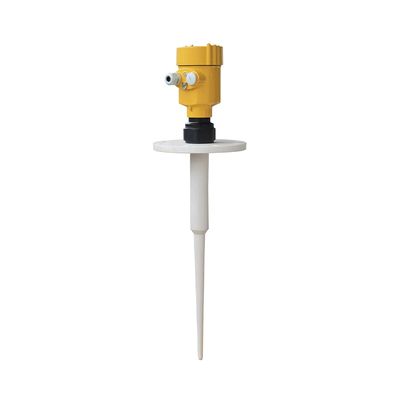
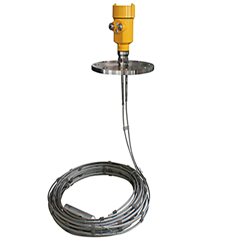
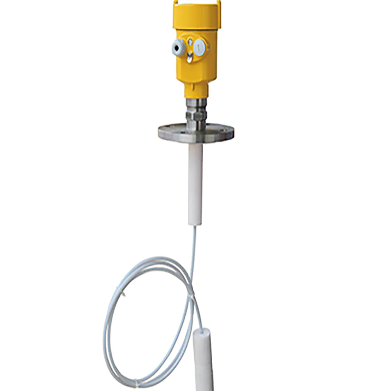
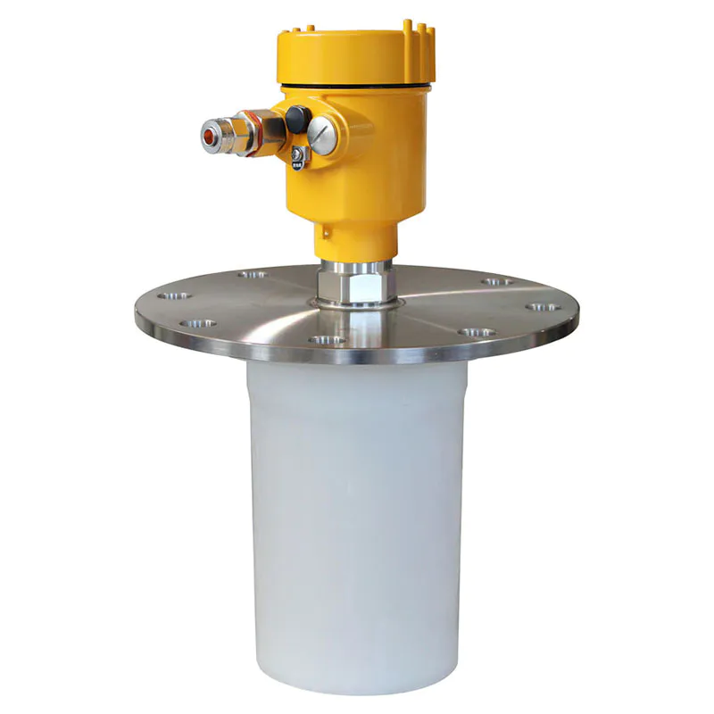
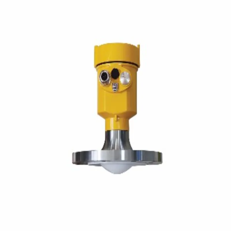
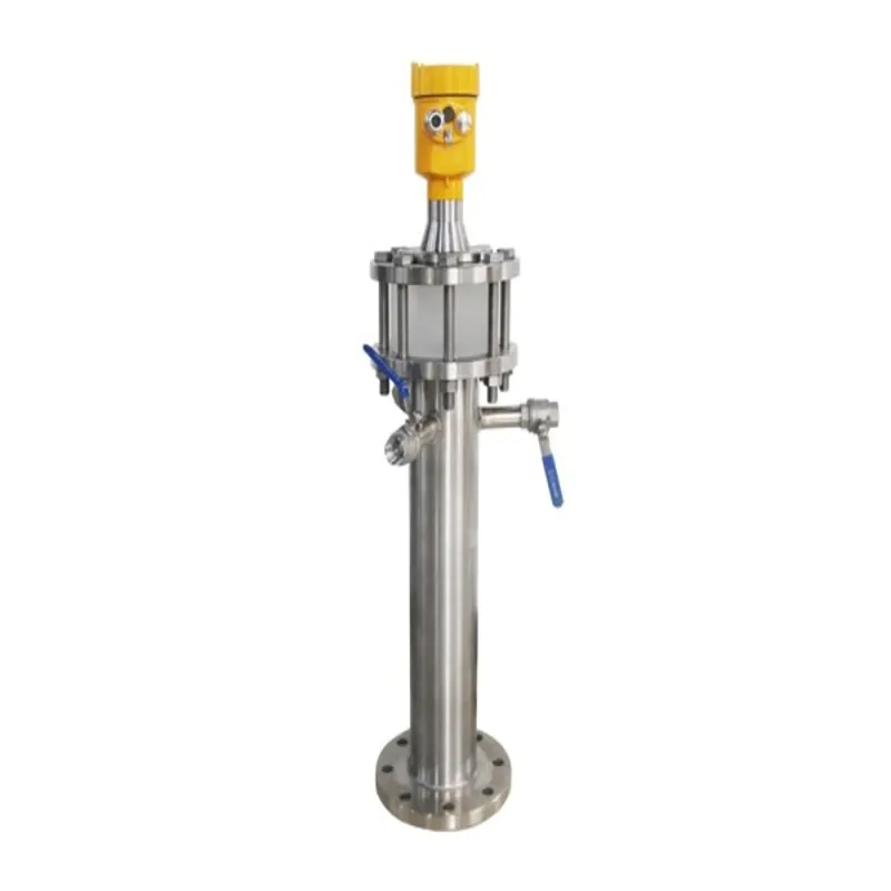
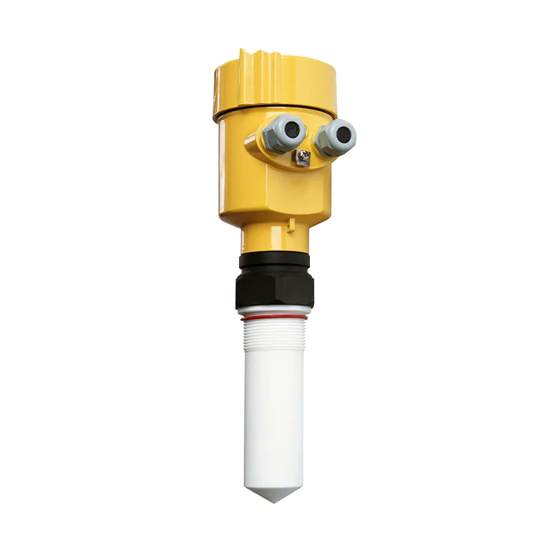
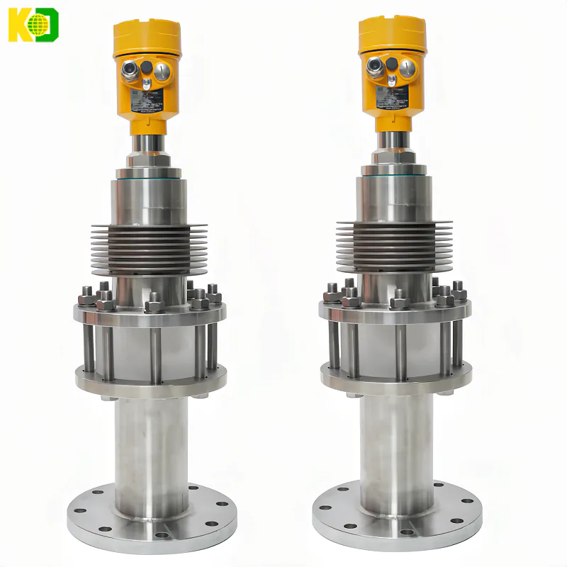
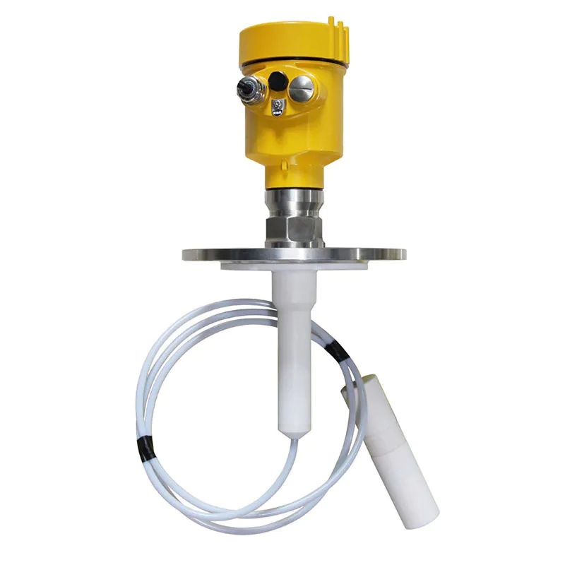
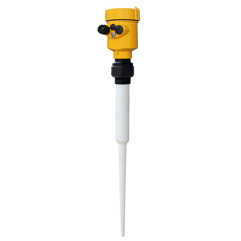
 Applications: temperature and pressure resistant, slightly corrosive liquids
Measuring range: 30 meters
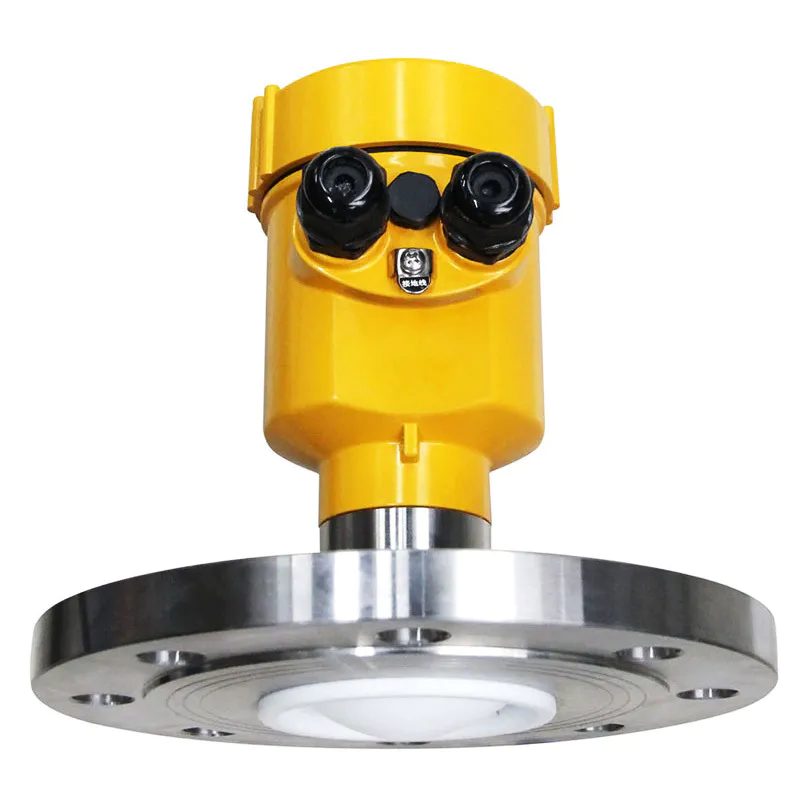
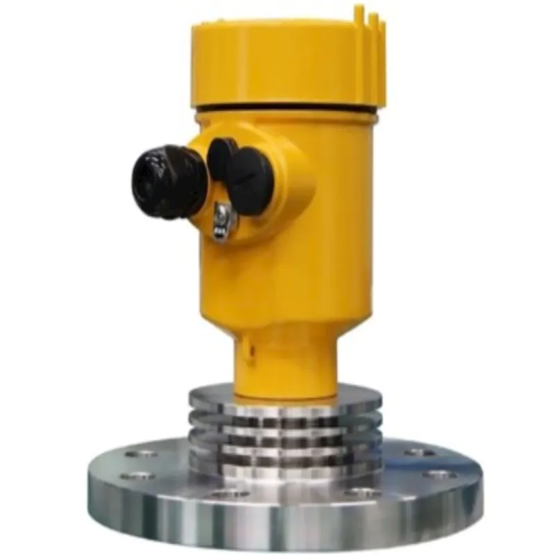
Process connection: thread, flange
Process temperature:-40~130℃( standard type ) / -40~250℃( high temperature type )
Process pressure: -0.1~4.0MPa
Accuracy:±3mm
Protection grade: IP67
Frequency range: 26GHz
Power supply: two-wire system (DC24V) / four-wire system (DC24V/AC220V )
Explosion-proof grade: Exia ⅡC T6 Ga / Exd IIC T6 Gb
Housing: Aluminum single cavity / Aluminum double cavity / Plastic / Stainless steel single cavity
Signal output: 4.... .20mA/HART ( two wire / four wire ) / RS485 Mod bus
Process connection : Thread G1½"A / Thread 1½"NPT / Flange
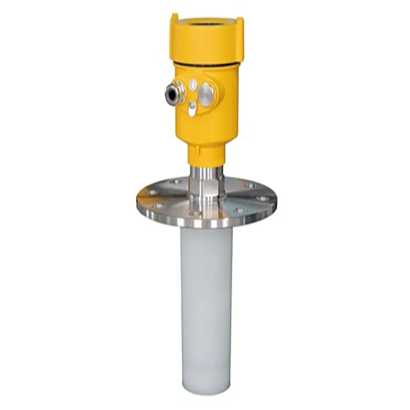
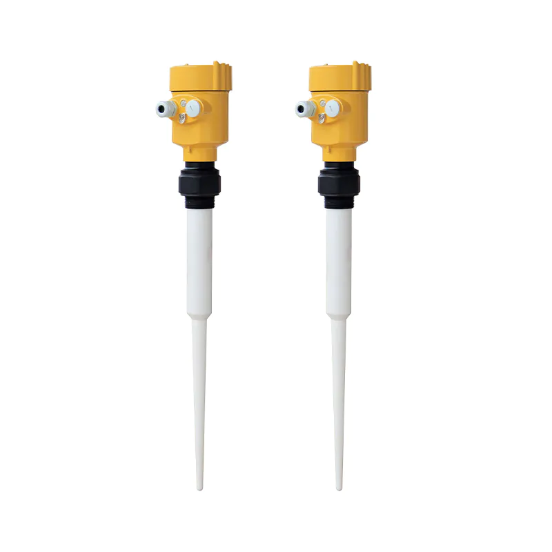
Antenna profile: stainless steel / PTFE
Housing: Seal between housing and housing cover Silicone rubber
Housing window: PolycarbonateGrounding terminal: Stainless steel
Supply voltage: 2-wire Standard (16 to 26) V DCIntrinsically safe (21. 6 to 26. 4) V DCPower consumption max 22. 5mA / 1WAllowable ripple
Explosion-proof type - <100Hz Uss < lV- (100 to 100K) Hz Uss < l0mV(22. 8 to 26. 4) V DC Two-wire system(198 to 242) V AC four-wire / 110V AC four-wire
Cable parameters: Cable inlet/plug 1 M20xl.5 cable inlet1 blind plug M20xl.5
Wiring terminals: Wire cross section 2.5 mm²
Output parameters: Output signal (4 to 2 0) mACommunication protocol HARTResolution 1. 6 μA
Fault signal Current output constant20. 5mA22mA;3.9mA
Integration time: (0~36)s, adjustableBlind area End of antenna
Maximum measuring distance: KD-901 10m (liquid type)KD-902 30m (liquid type)
KD-902T 20m (liquid type)KD-903 70m (solid type)
KD-904 80m(solid type)KD-905 30m(solid type)
KD-906 20m (Liquid type)Microwave frequency :26GHz
Communication interface: HART communication protocol
Measurement interval: approx. 1 second (depending on parameter settings)
Adjustment time: approx. 1 second (depending on parameter setting)
Display resolution: 1mm
Operating storage and transport temperature : (-40~100) ℃
Process temperature (temperature of the antenna section): KD-901 (-40 to 130) °C KD-902 (-40~250)℃
KD-902T (-40~250)℃KD-903 (-40~250)℃
KD-904 (-40~250)℃KD-905 (-40~250)℃
KD-906 (-40~200)℃Relative humidity: ˂95%
Pressure : Max. 4MPa
Shock resistance: Mechanical vibration l0m/s² , (10~150)Hz
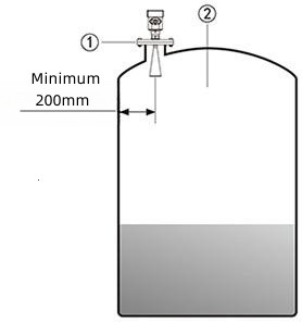
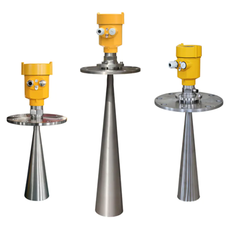
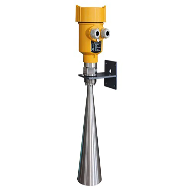
Install at 1/4 or 1/6 of the diameter.Note: The minimum distance from the tank wall should be 200mm.Note: ① datum plane; ② central or symmetry axis of the vessel
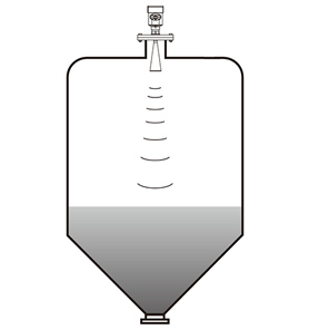
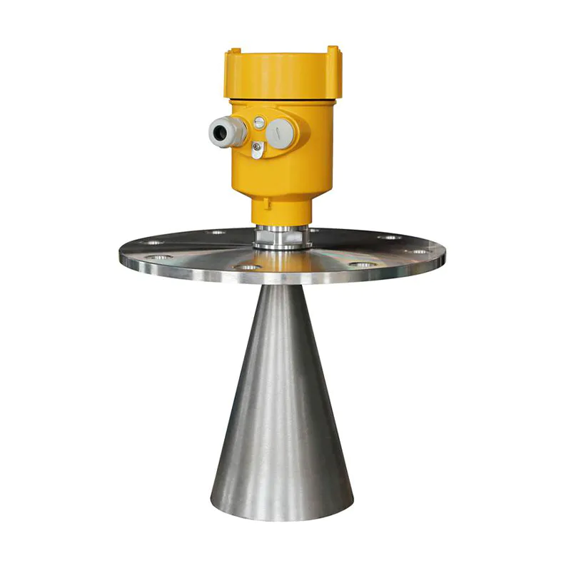
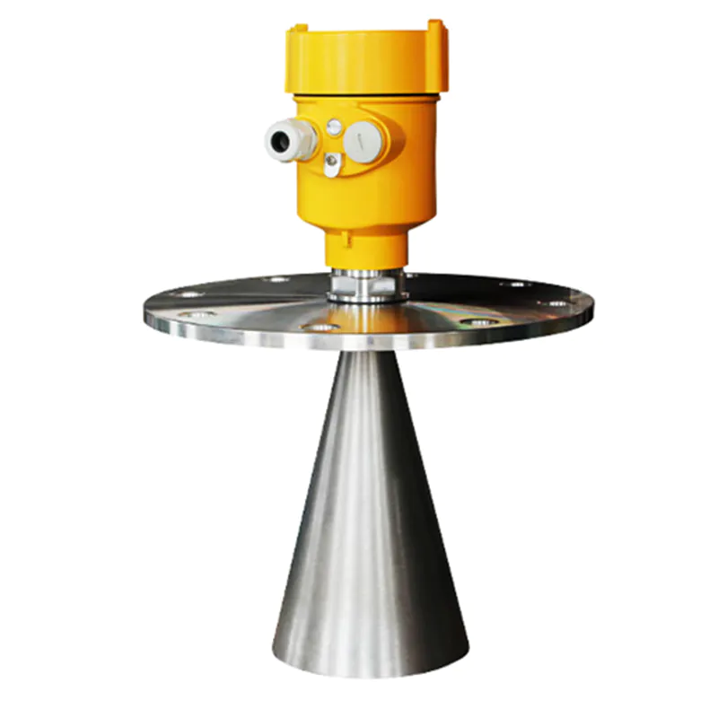
The flat top of the conical tank, which fits right in the middle of the tank top, ensures measurement to the bottom of the cone.
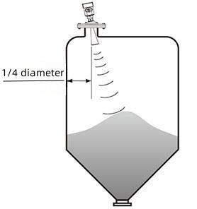
When there is a material pile, the antenna should be aligned with the material surface vertically. If the material surface is not flat and the pile angle is large, you must use the universal flange to adjust the horn angle so that the horn is aligned with the material surface as much as possible. (Due to the inclined solid surface will cause echo attenuation, and even loss of signal problems)
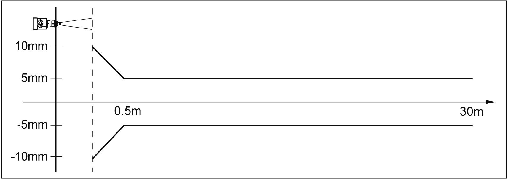
Meter Linearity
902
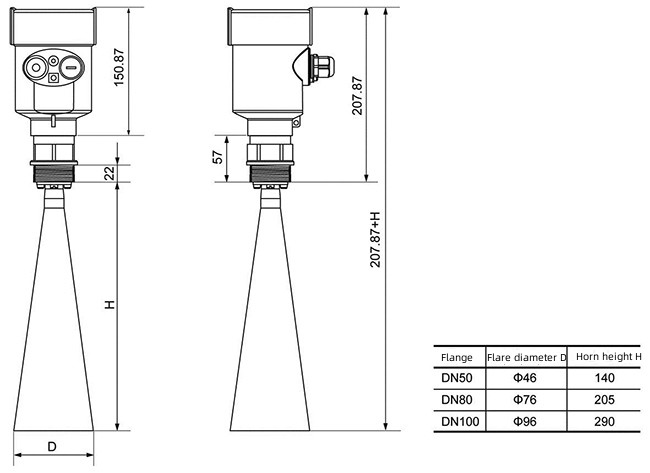
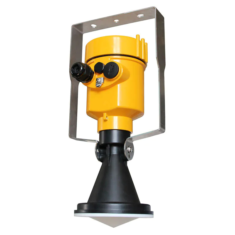
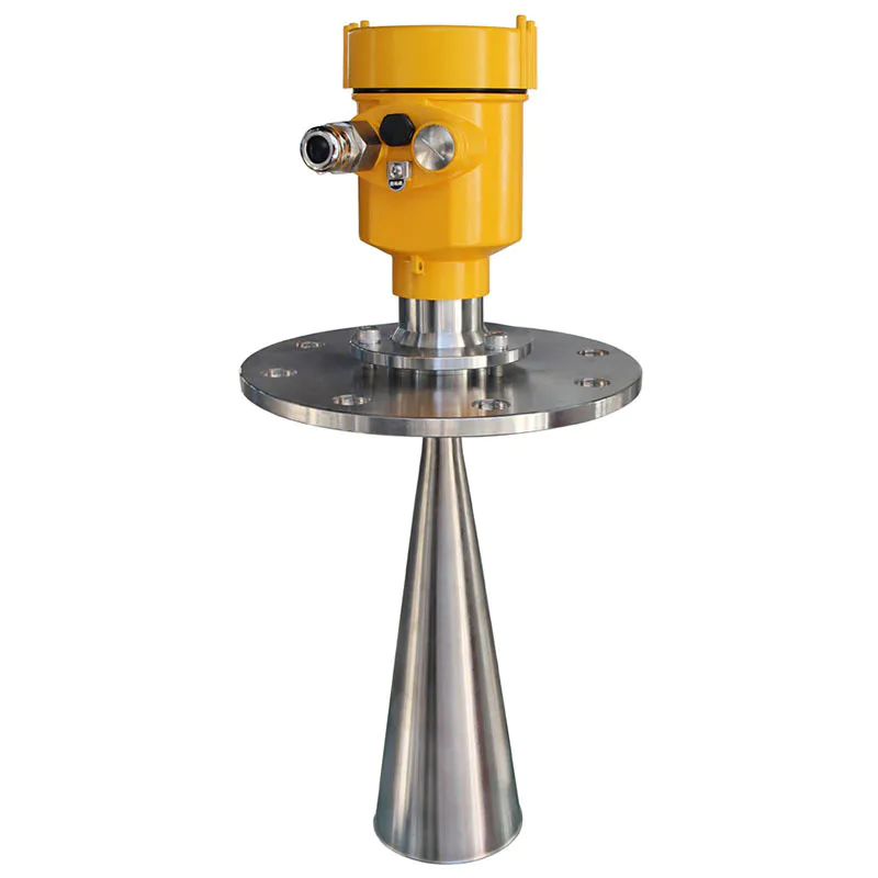
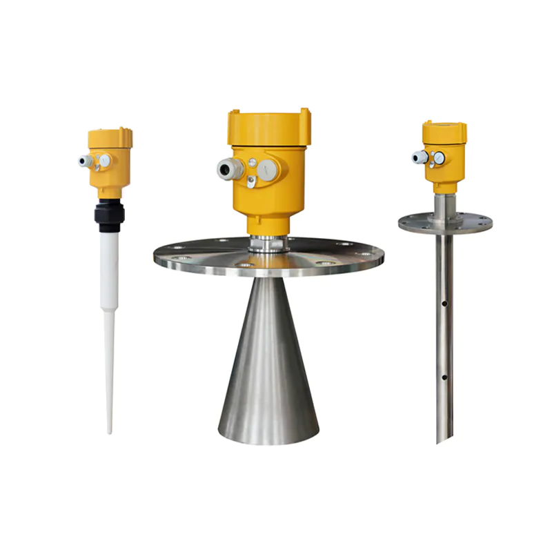
The launch angle depends on the antenna size
-¢46mm 18°
-¢76mm 12°
-¢96mm 8°
-¢121mm 6°
Accuracy See below(±5mm)
The Electrical Connection
The power supply voltage:
(4~20)mA/HART (Two wire system) | The power supply and the output current signal sharing a two core shield cable. The supply voltage range see technical data. For intrinsically safe type must be a safety barrier between the power supply and the instrument. |
| (4~20)mA/HART(Four wire system) | Separate power supply and the current signal, respectively using a two-core shielded cable. The supply voltage range see technical data. |
| RS485 / Modbus | Power supply and Modbus signal line separated respectively using a two-core shielded cable, the power supply voltage range see technical data. |
Cable Connection
General Introduction | Supply cable can use ordinary two-core cable, the cable diameter should be (6~12) mm, to ensure that the cable entry seal. If electromagnetic interference exists, recommended to use shielded cable. |
(4~20) mA /HART(Two-wire) | Supply cable can use ordinary two-core cable. |
(4~20) mA /HART(Four-wire) | Supply cable should be used with a dedicated ground cable |
Modbus-RS485(Four-wire) | Shielded cable should be used for the power supply cable. |
| Shielding and wiring | Both ends of the shielded cable should be grounded. Inside the sensor, the shield must be connected to the internal ground terminal. The external ground terminal on the enclosure must be connected to the ground. If there is ground current, the shielded cable must be grounded through a ceramic capacitor (for example: 1nF/1500V) far away from the shielding end of the instrument side to block direct and bypass high-frequency interference signals. |
Connection mode
Ø 24V two wire wiring diagram as follows:
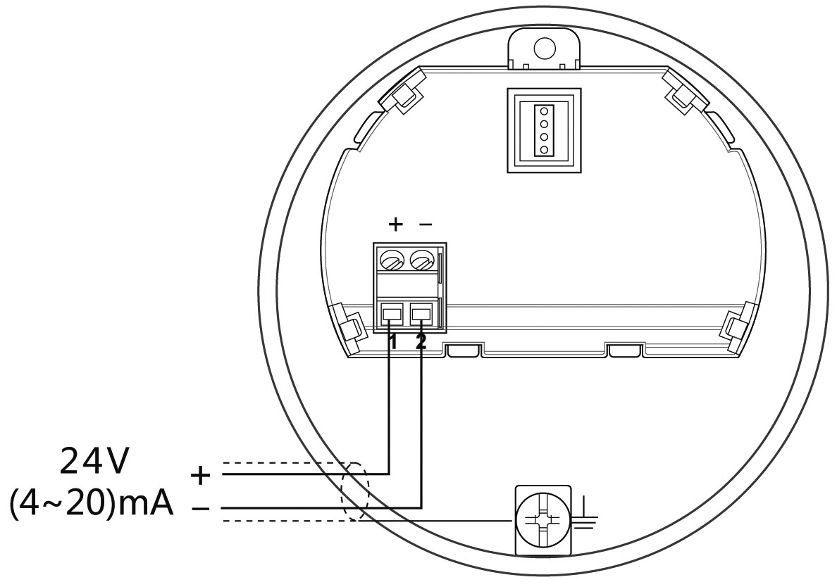
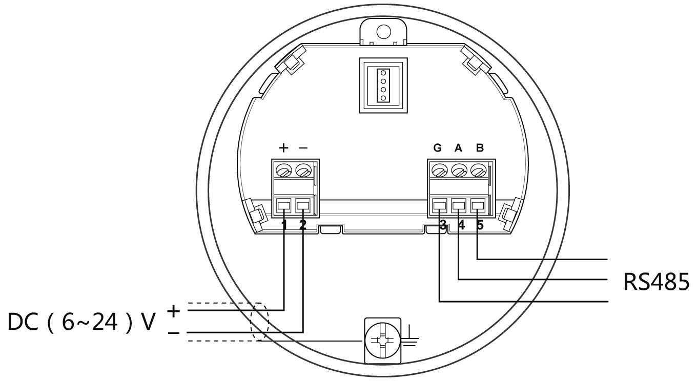
Ø 6~24V Modbus-RS485 wiring diagram as follows:
Explosion Proof Connection
The explosion-proof form of this product is intrinsically safe.The intrinsic safety version sensors (Exia Ⅱc T6) use Alu-die casting housing and filling Silicone rubber sealants internal structure aimed to prevent sparks resulted from circuit failure from leaking out. It is applicable for the continuous level measurement of flammable medium under Exia Ⅱc T6.
A safety barrier FBS-2 must be used together with the intrinsic safety instrument. It is an associated device to this product for the power supply of this product. The main specification is intrinsic safety: ExiaⅡc, voltage of power supply: 24V DC±5%, short-circuit current: 135mA, operating current: 4...20mA.
All cables must be shielded. The max length is 500m for the cable from the barrier to the sensor. Stray capacitor≤0.1μF/Km, stray inductance 1mH/Km. Instrument must be connected to the ground potential. Any unapproved associated device is not allowed to be used.
Safety instructions:
Ø Please observe the local electrical code requirements!
Ø Please comply with local requirements for personnel health and safety regulations.
All electrical components of instrument operation must be completed by the formal training of professionals.
Ø Please check the instrument nameplate to provide product specifications meet your requirements. Please make sure that the power supply voltage and instrument nameplate on the requirements.
Protection grade:
This meter fully meets the requirements of protection class IP66/IP67, please ensure the waterproof characteristics of the cable seal. As shown below:
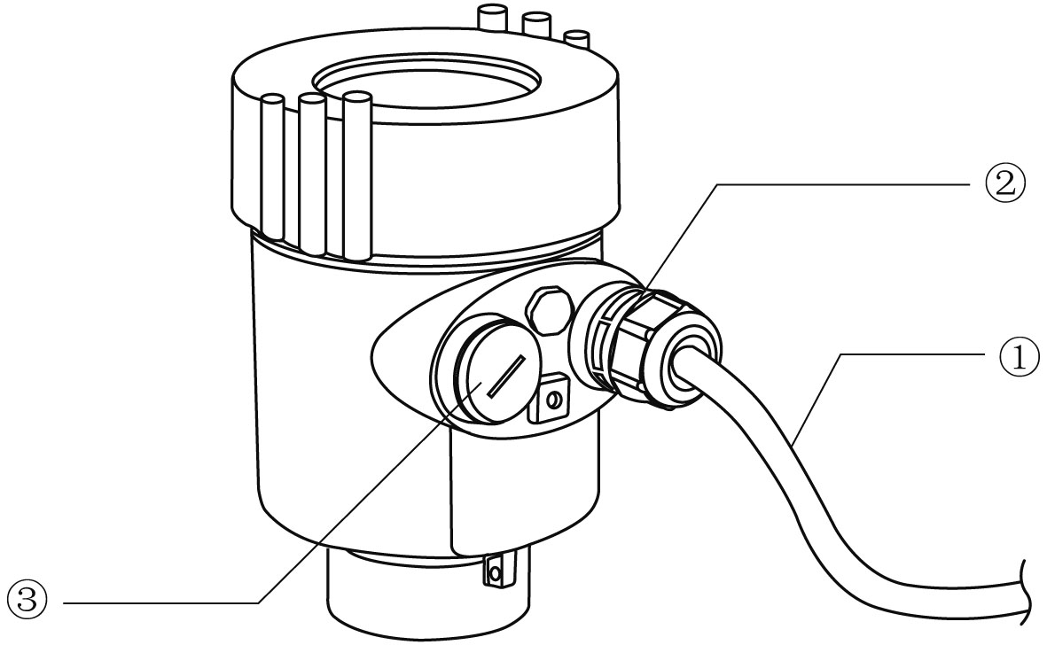
How to install to meet the requirements of IP67:
Please make sure that the sealing head is not damaged.
Please make sure that the cable is not damaged.
Please make sure that the cable for use with electrical connection specification.
Cable into the electrical interface before its curved downward, ensure that the water will not flow into the shell, see the①
Tighten the cable seal head, see the②
Please electrical interface will not use blind plug tight, see the③
Instrument Commissioning
Three kinds of debugging method:
1) Display / Button (With split display, you need to debug on the split)
2) Debug through computer software
3) HART Handheld programmer
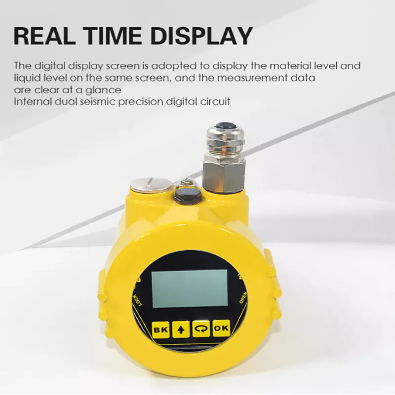
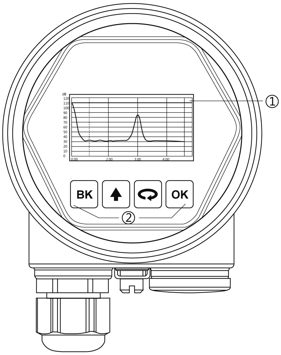
Display / Button:
Debug the meter through the 4 buttons on the display screen. The debugging menu has four languages to choose from. The measured value can be read very clearly through the glass window.
Display / Button
① Liquid crystal display(LCD) ② Adjust by button
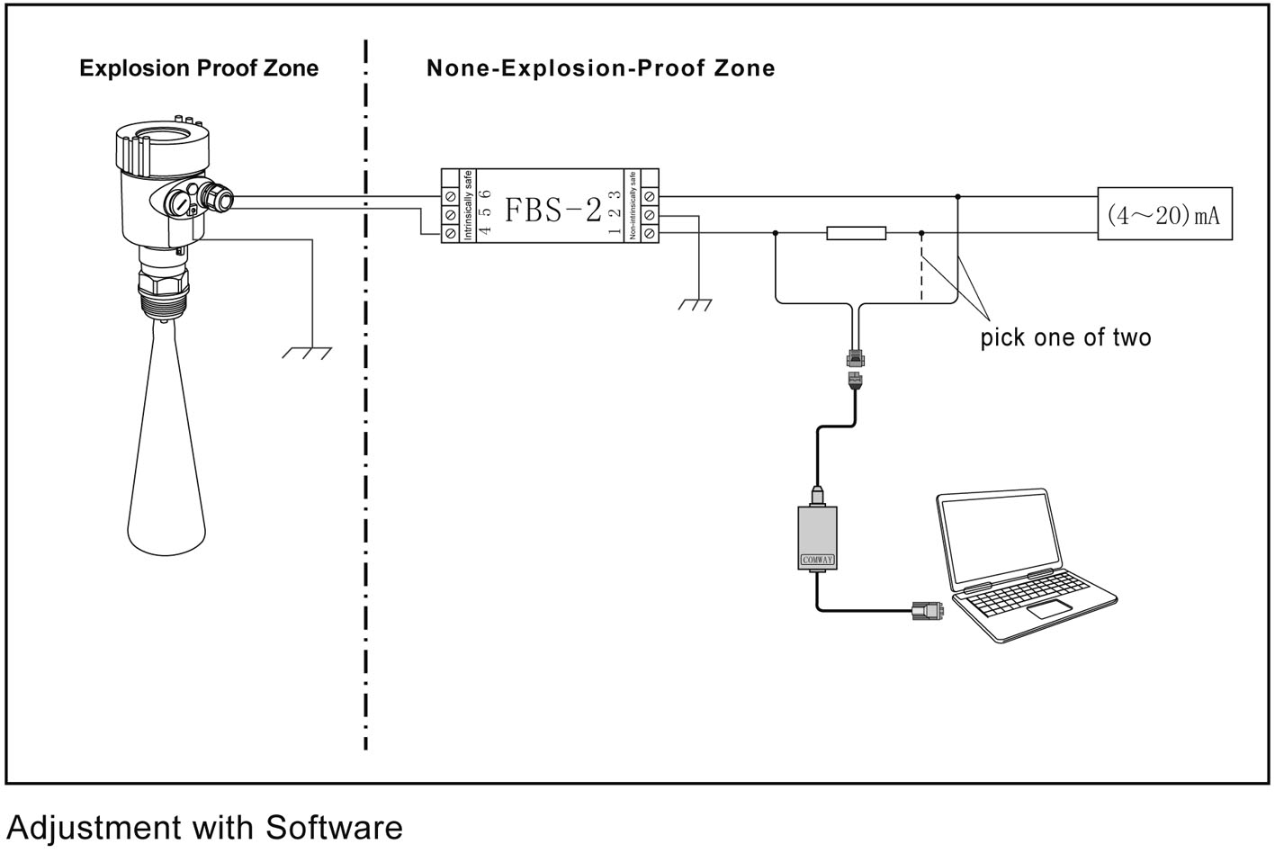
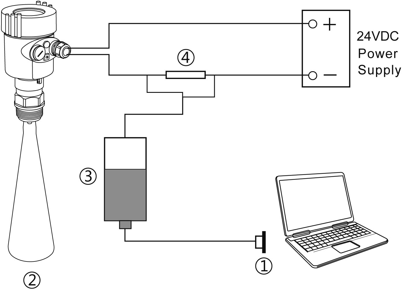
PC debugging:
Connected to PC by HART
① USB interface ② Radar level meter ③ HART converter ④ 250Ω resistor
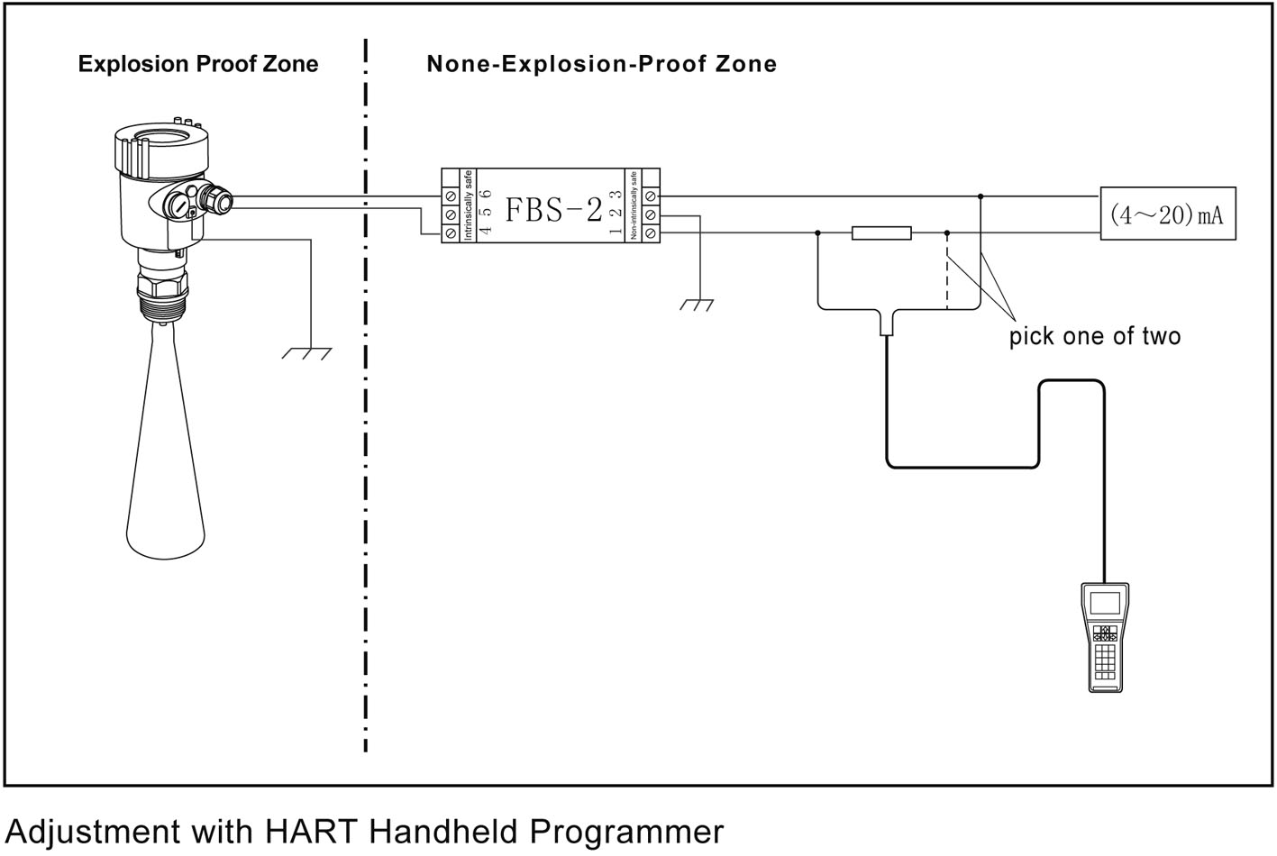
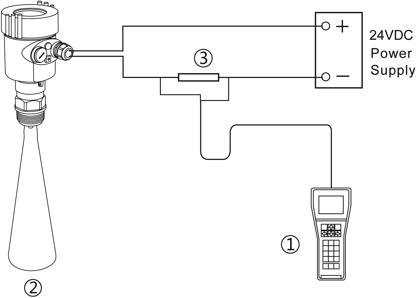
HART handheld programmer:
① HART handheld programmer ② Radar level meter ③ 250 Ω Resistor
Product Model Selection
902
License | |||||||||||||||
P Standard (Non-explosion-proof) I Intrinsically safe (Exia ⅡC T6 Ga) D Flameproof (Exd ⅡC T6 Gb) | |||||||||||||||
Process Connection / Material | |||||||||||||||
G Thread G1½″A / Stainless Steel 304 N Thread 1½″ NPT / Stainless Steel 304 Y Special Custom | |||||||||||||||
| |||||||||||||||
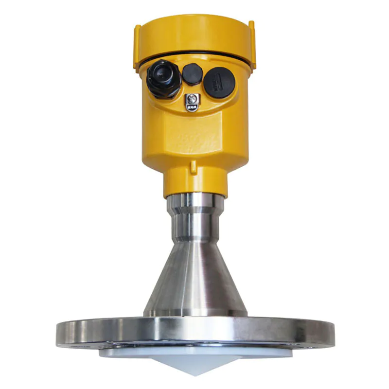
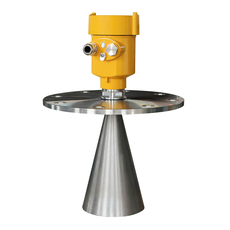
Antenna Type / Material | |||||||||||||||
A Horn Antenna Φ46mm / Stainless Steel 316L B Horn Antenna Φ76mm / Stainless Steel 316L C Horn Antenna Φ96mm / Stainless Steel 316L Y Special Custom | |||||||||||||||
Seal Up / Process Temperature | |||||||||||||||
V Viton / (-40~130) ℃ K Kalrez / (-40~230) ℃ | |||||||||||||||
The Electronic Unit | |||||||||||||||
3 (4~20) mA / 24V DC / HART 2-wire system 4 (4~20) mA / 220V AC / HART 4-wire system 5 Modbus-RS485 / 6~24V / 4-wire system | |||||||||||||||
Outer Covering / Protection Grade | |||||||||||||||
L Aluminum / Single chamber / IP67 H Aluminum / Double chamber / IP67 G Plastic / Single chamber / IP65 K Stainless steel / Single chamber / IP67 | |||||||||||||||
Cable Line | |||||||||||||||
M M 20×1.5 N ½″ NPT | |||||||||||||||
Field Display /The Programmer | |||||||||||||||
A With X Without | |||||||||||||||
We are here to help you! If you close the chatbox, you will automatically receive a response from us via email. Please be sure to leave your contact details so that we can better assist


![kaidi KD-906 26G Radar Level Meter [Anti-corrosion] High Temperature Intelligent](https://img80003270.weyesimg.com/uploads/kaidi86.com/images/16760218661446.jpg?imageView2/2/w/1920/q/80/format/webp)


![kaidi KD-802 6G Radar Level Meter [Anti-corrosion Type]](https://img80003270.weyesimg.com/uploads/kaidi86.com/images/15936739299092.jpg?imageView2/2/w/1920/q/80/format/webp)
![kaidi KD-FMF15 FM radar level meter [chemical and electric power industry]](https://img80003270.weyesimg.com/uploads/kaidi86.com/images/15936722293812.jpg?imageView2/2/w/1920/q/80/format/webp)