Español
  pусский
  العربية
  Português
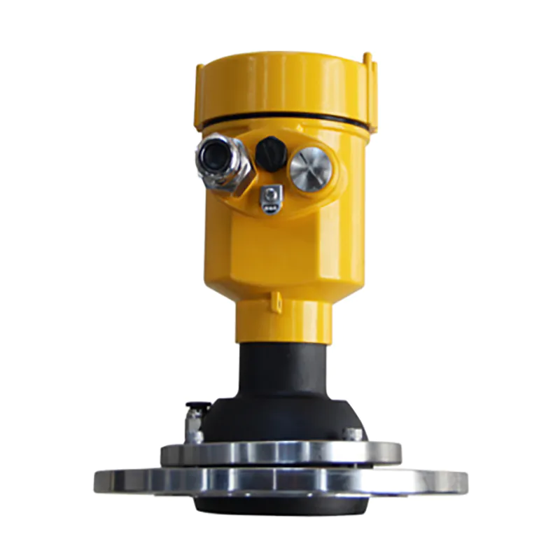
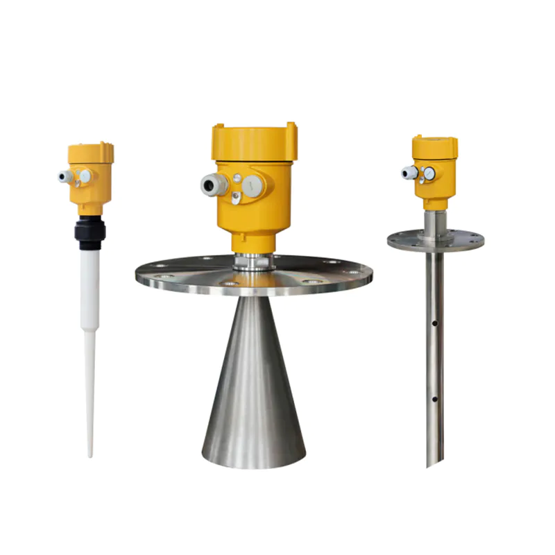
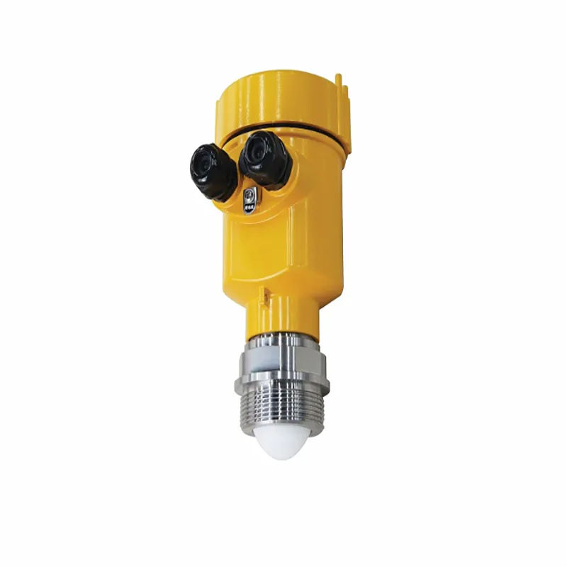
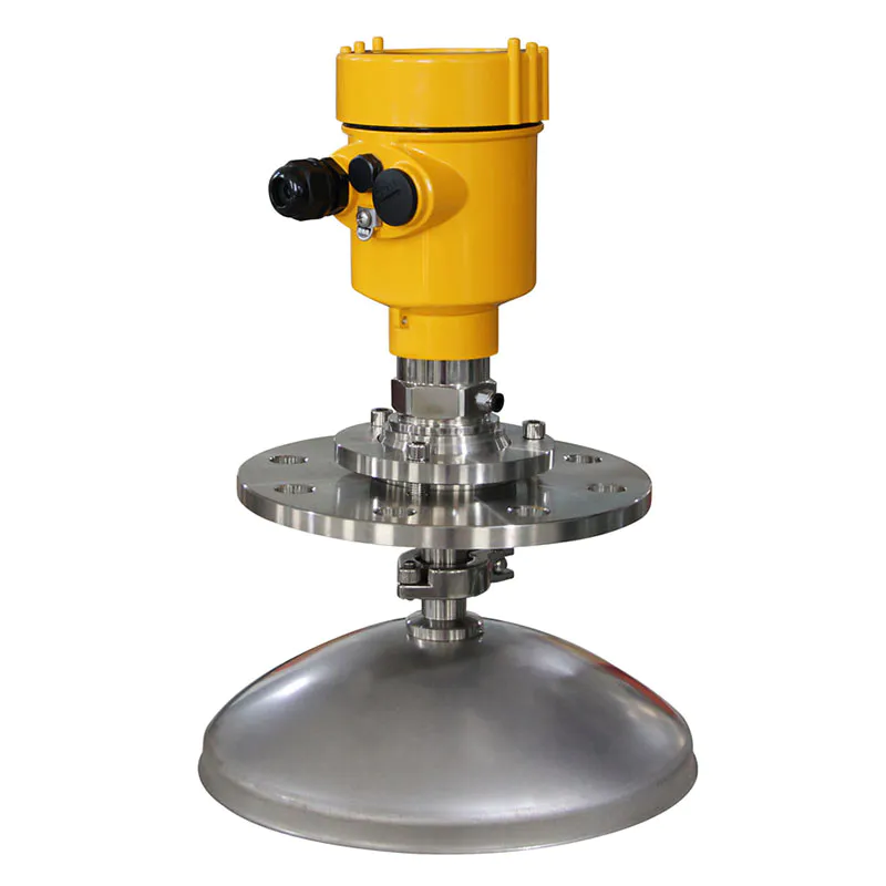
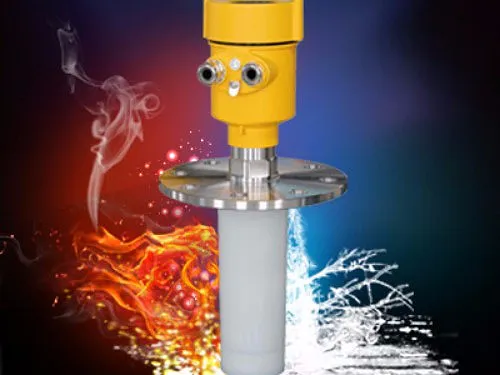
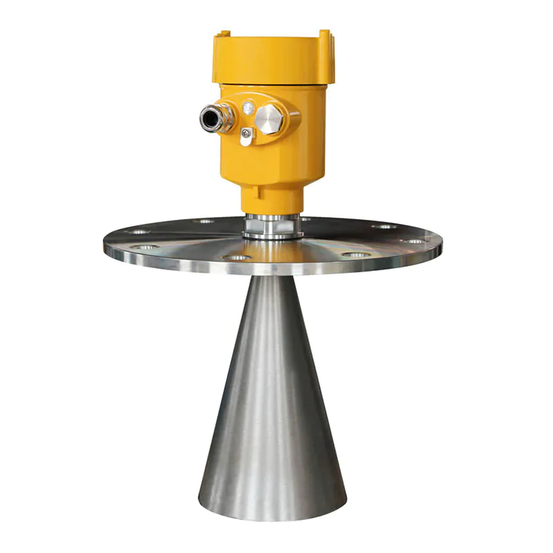
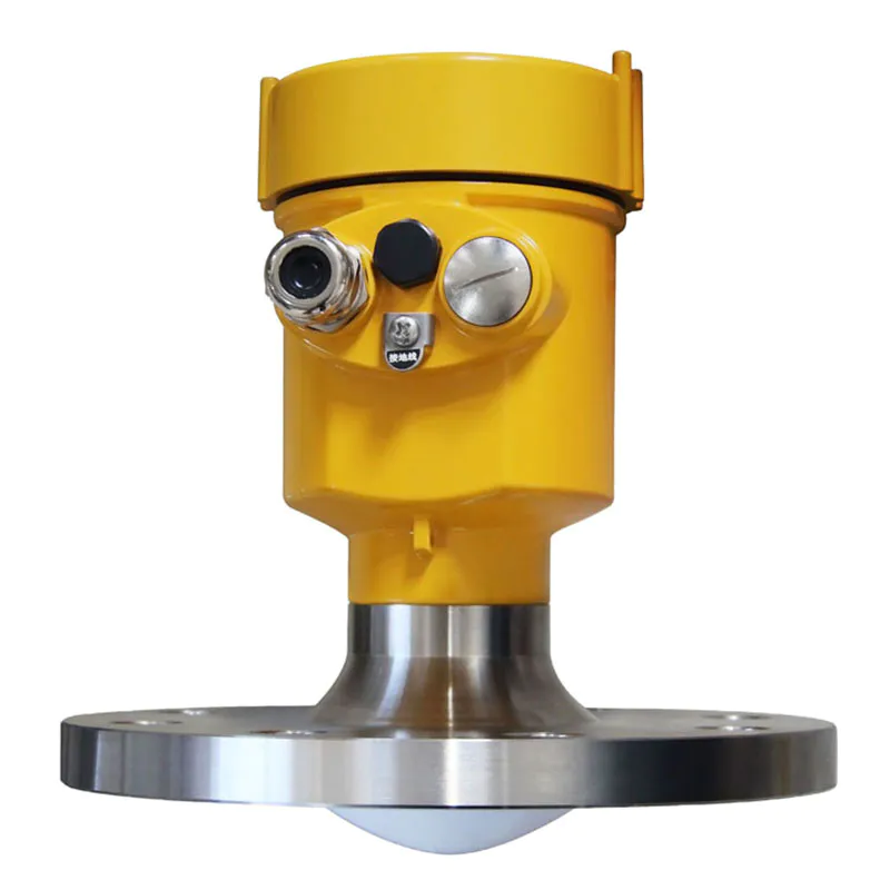
Radar Level Meter 80G FM Radar Type Level Measuring Instrument Kaidi KD-FMW21S FM
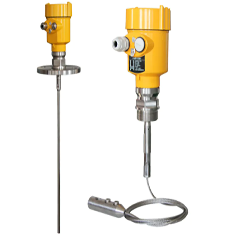
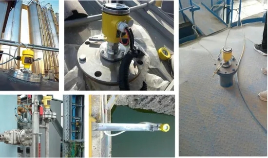
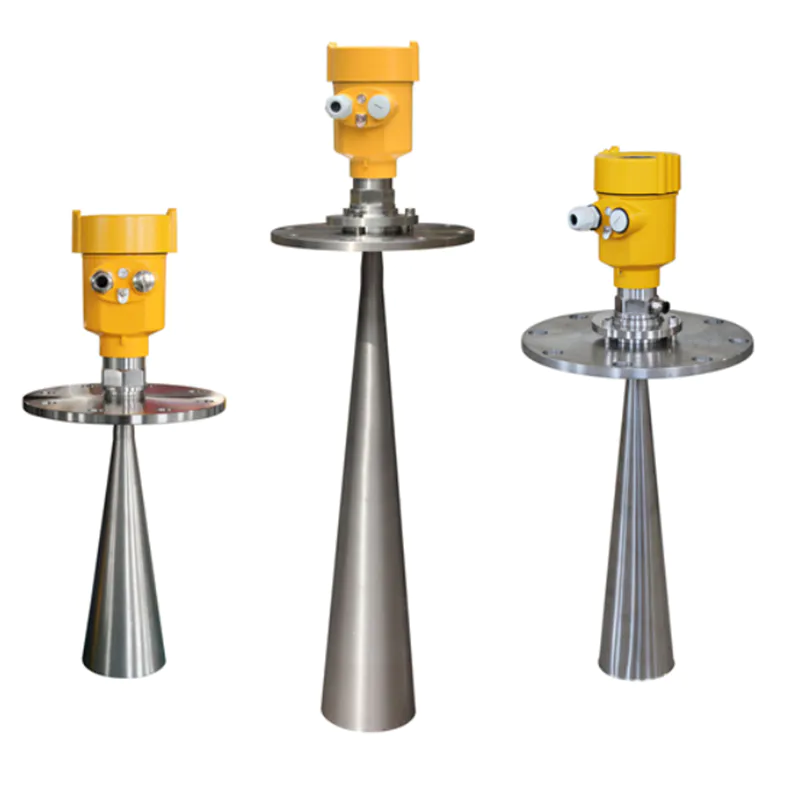
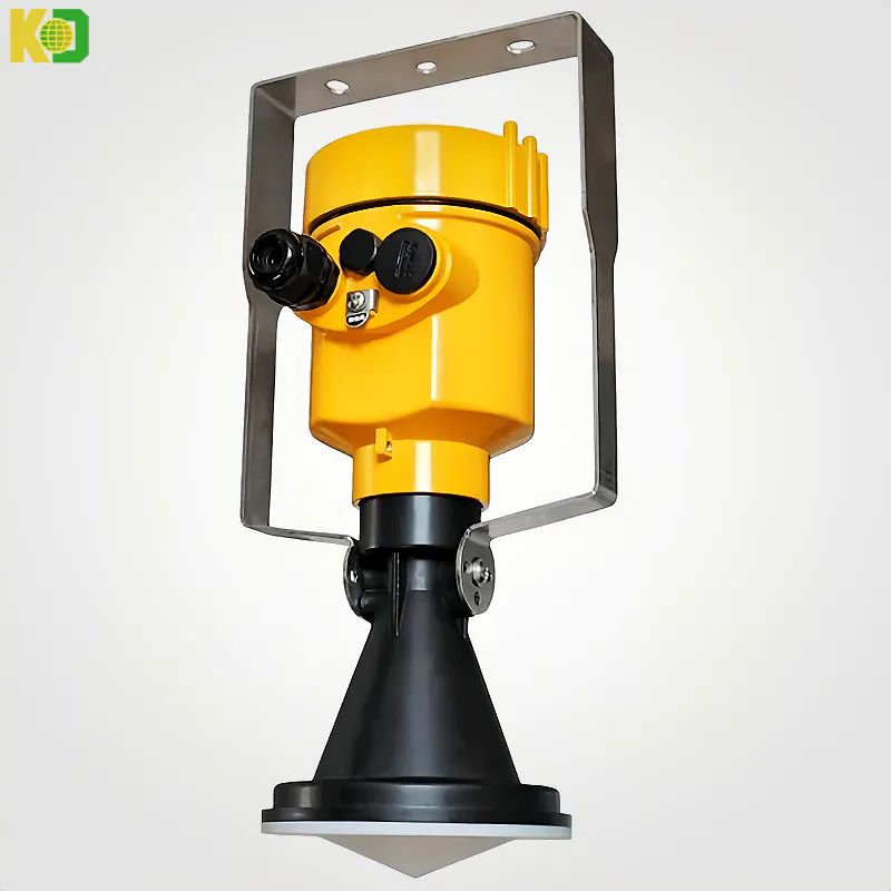
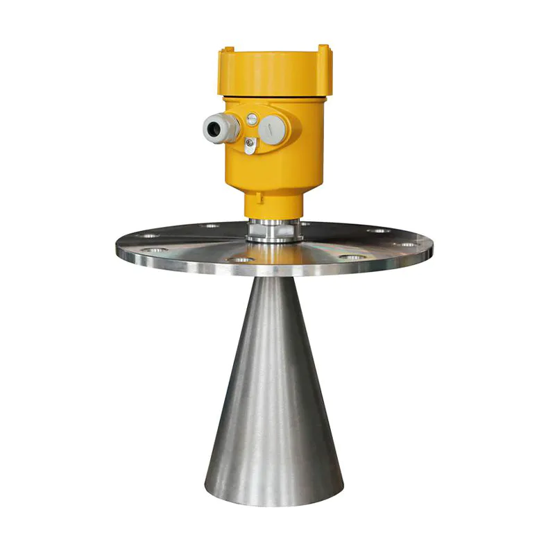
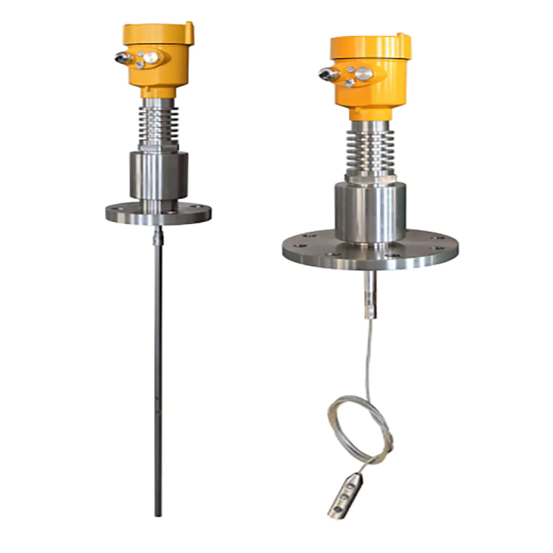
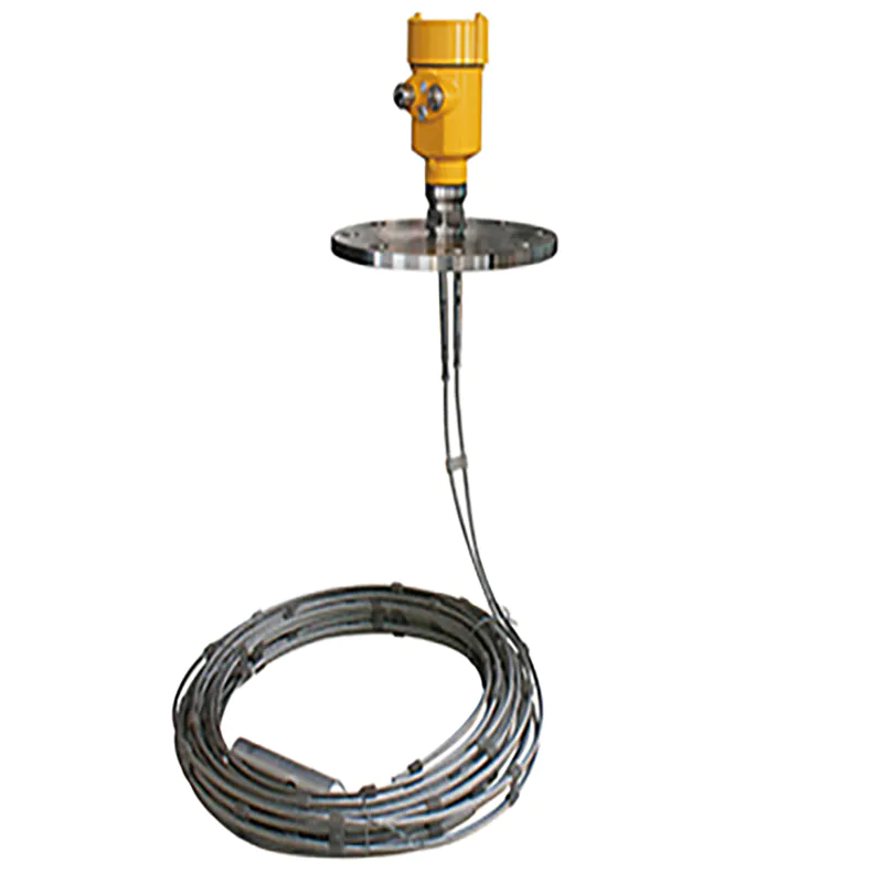
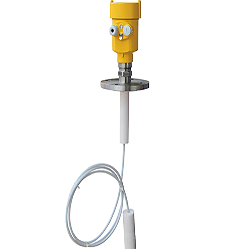
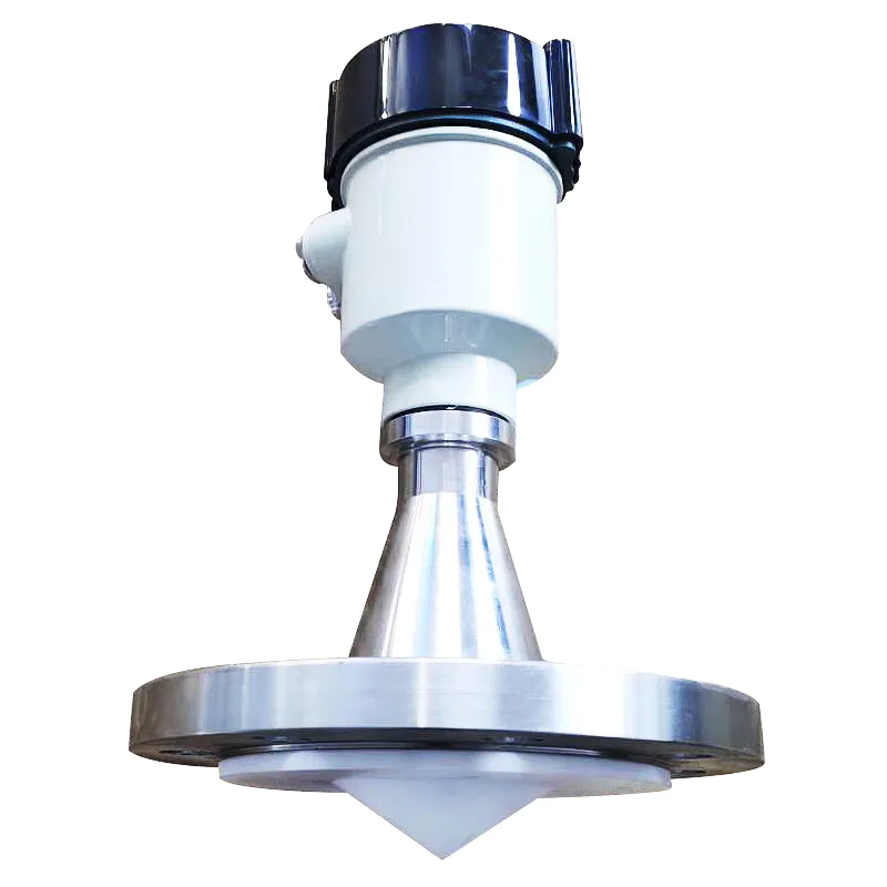
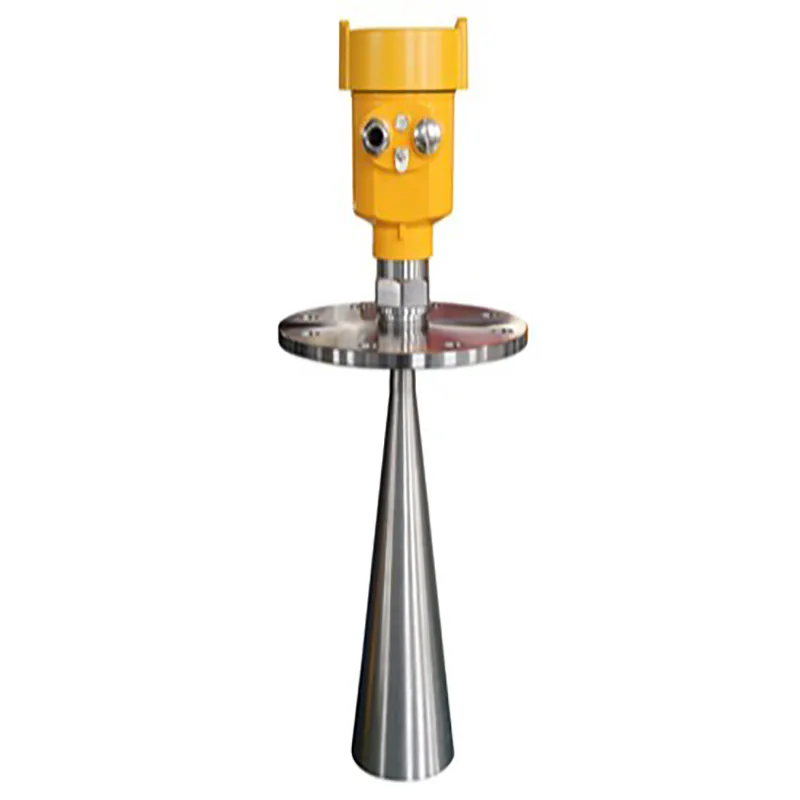
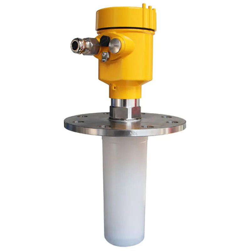
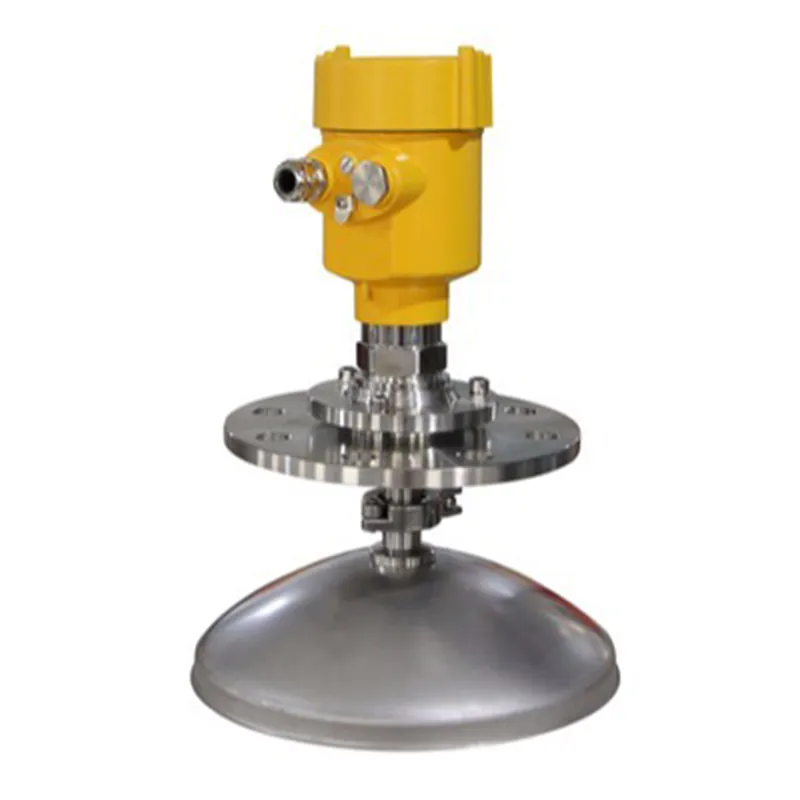
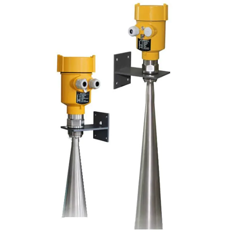
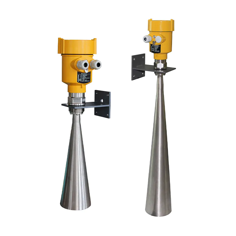
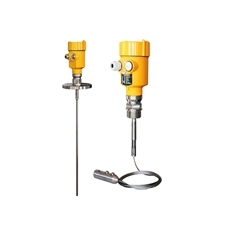
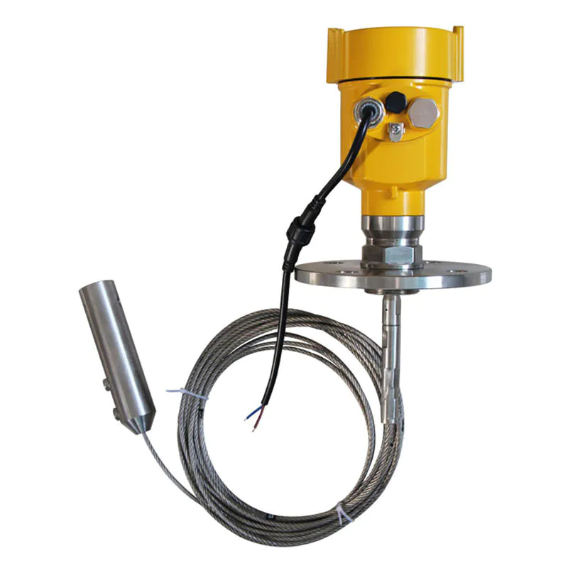
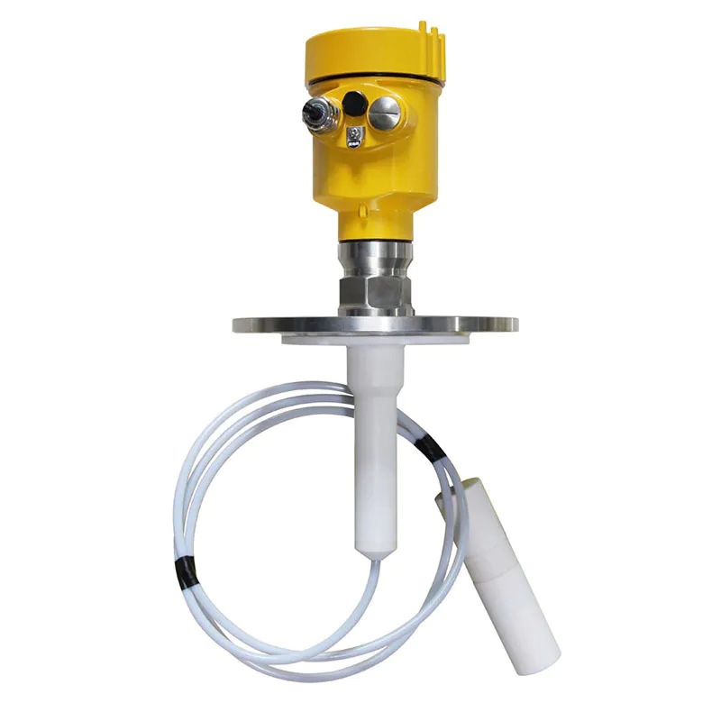
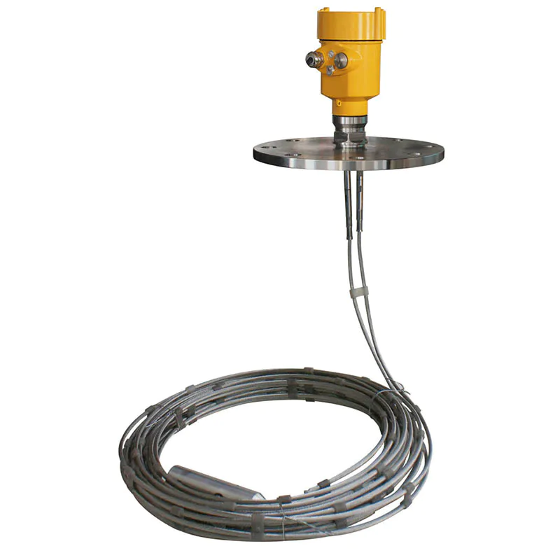
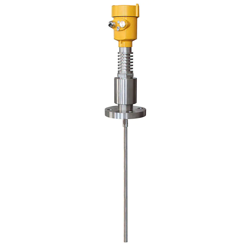
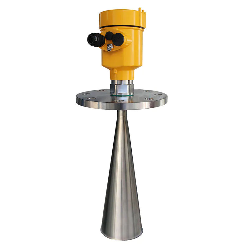
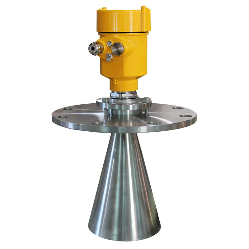
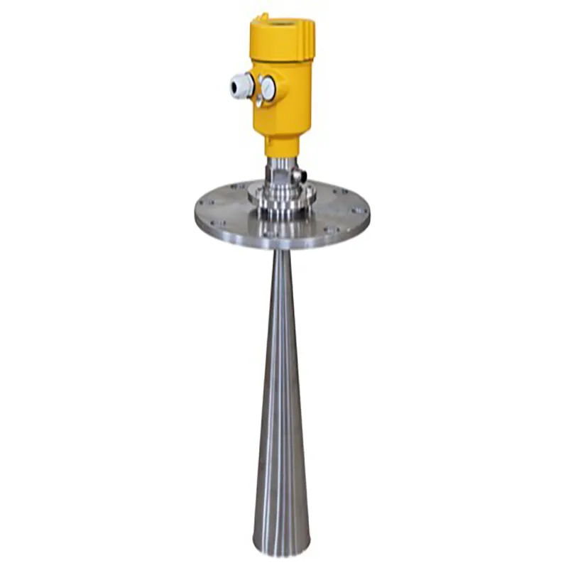
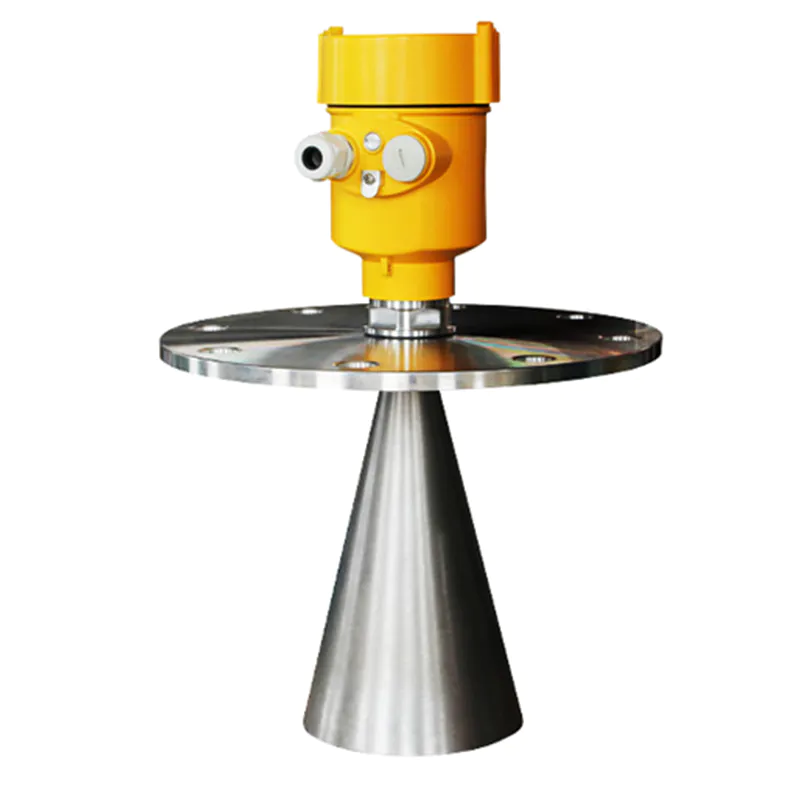
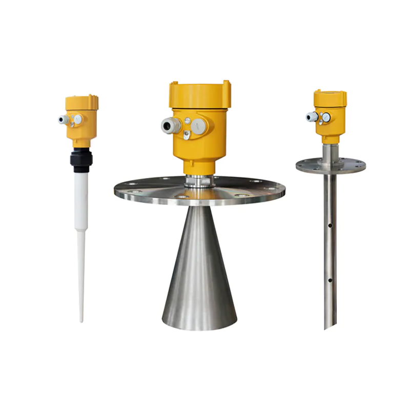
KDRD-FMW Series Sensor Is 80G FM Radar Type Level Measuring Instrument, Measuring Distance Up To 150 Meters
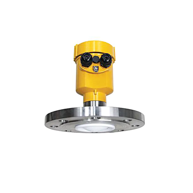
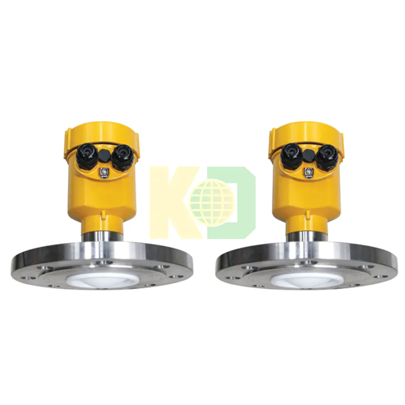
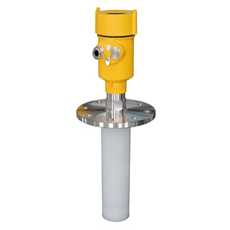
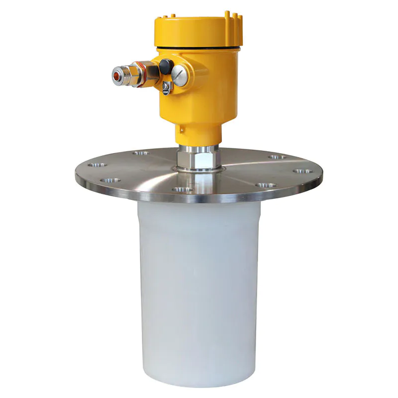
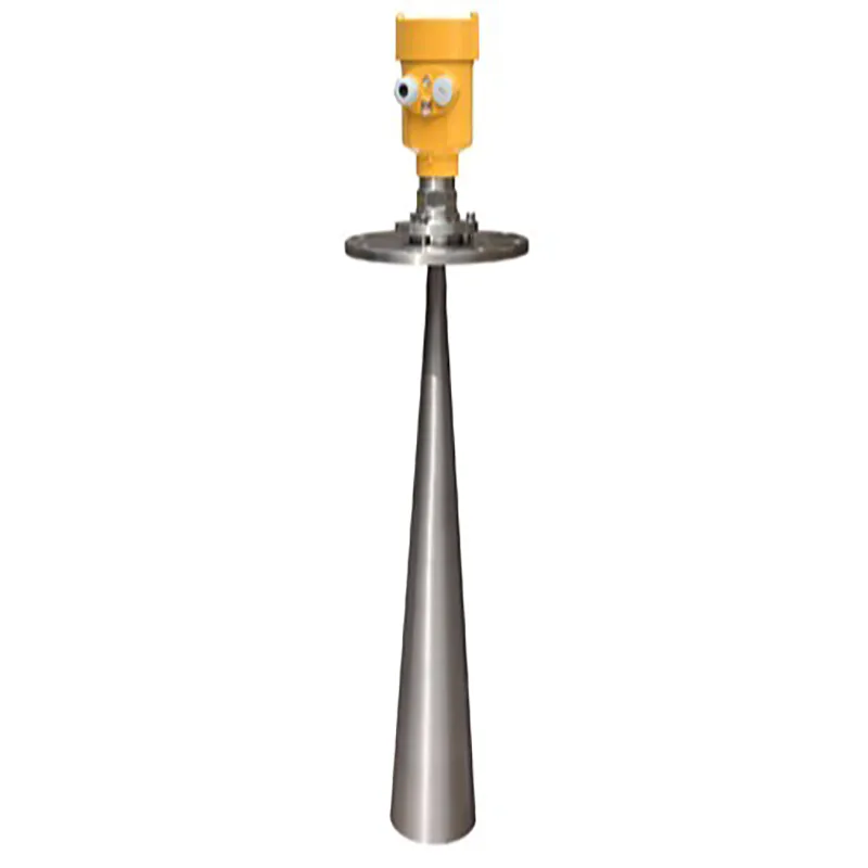
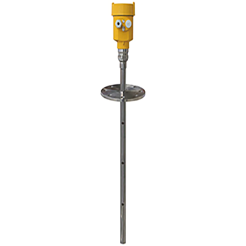
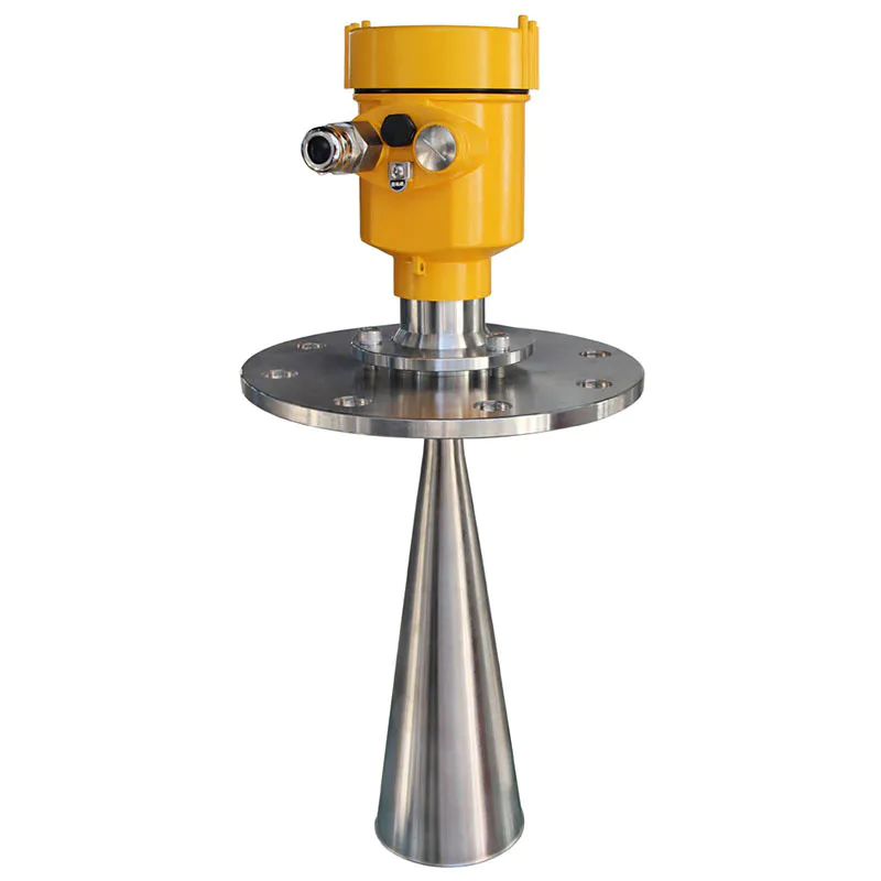
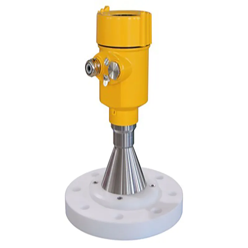
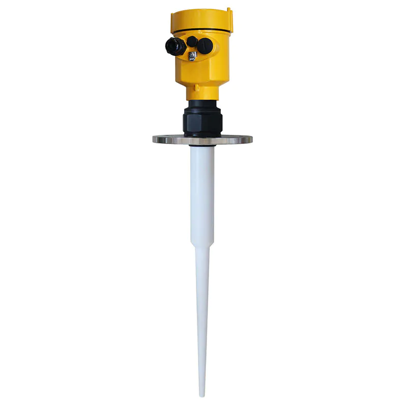
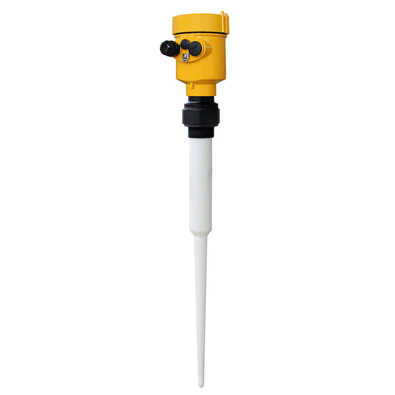
The kaidi KD-FMF series sensor is a 120G frequency modulation radar type level measuring instrument with a measuring distance of up to 150 meters. The antenna is further optimized, and the new and fast microprocessor can perform higher-speed signal analysis and processing, so that the meter can be used for measurement of environmental solids such as high temperature and high pressure.
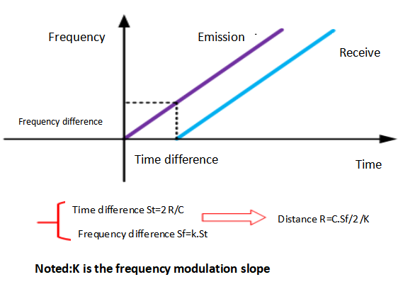
The general principle of the FM continuous wave radar level gauge is that the radar emits electromagnetic waves on the top of the tank, and the electromagnetic waves are received by the radar after being reflected by the medium. The frequency difference δ f between the received signal and the transmitted signal is proportional to the distance R from the surface of the medium. : R= C (speed) *δ f (frequency difference) /2/K (frequency modulation slope). Because the speed of light C and the frequency modulation slope K are known, the frequency difference δ f can be estimated to obtain the distance R of the material surface at the radar installation position, and then through the known total height of the tank, subtract the spatial distance from the radar to the material surface ( Referred to as the air height), the height of the material level is obtained.
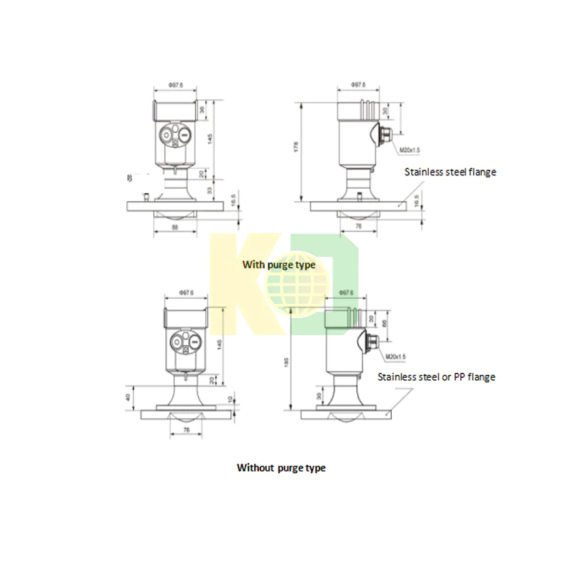
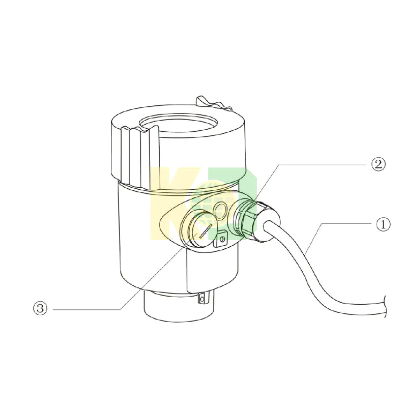
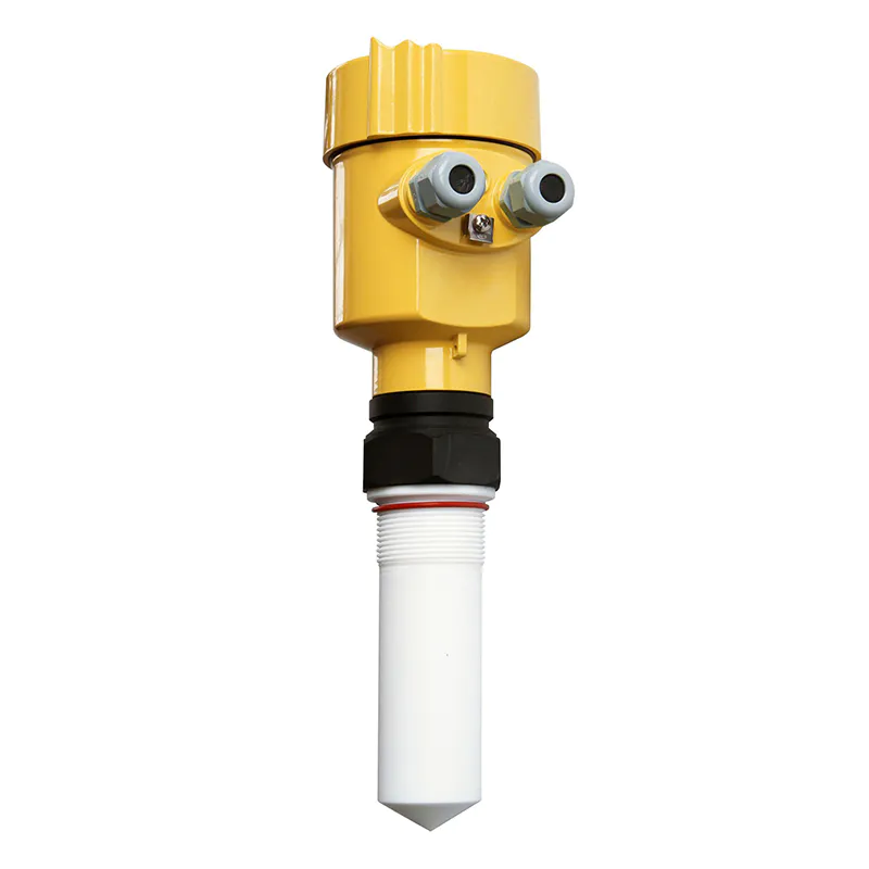
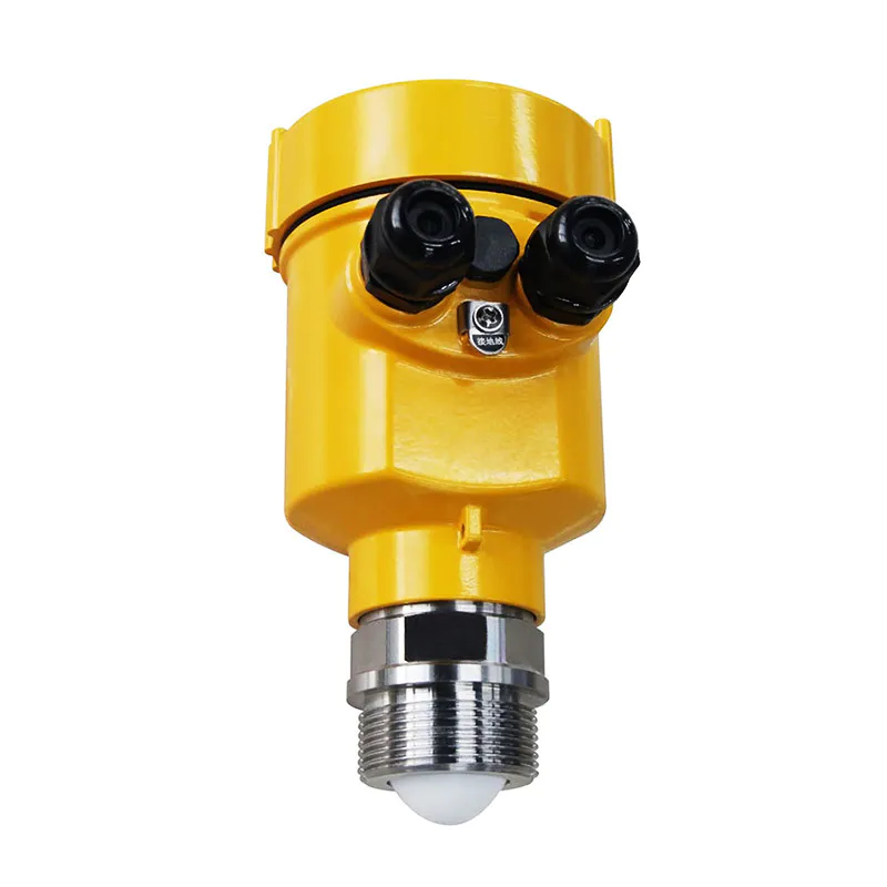
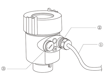 This meter fully meets the requirements of protection class IP66/67,
please ensure the waterproofness of the cable sealing head. As shown
How to ensure that the installation meets the requirements of IP67:
Make sure that the sealing head is not damaged.
Make sure that the cable is not damaged.
Make sure that the cables used meet the requirements of the
electrical connection specifications.
Before entering the electrical interface, bend the cable downward to
ensure that water does not flow into the housing, see ①
Please tighten the cable sealing head, see ②
Please block the unused electrical interfaces with blind plugs, see ③
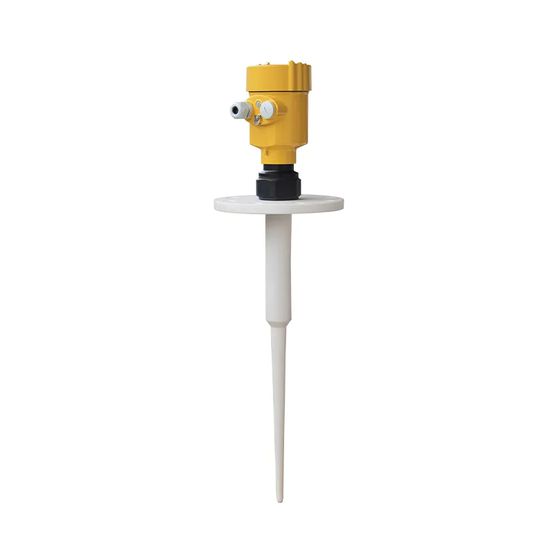
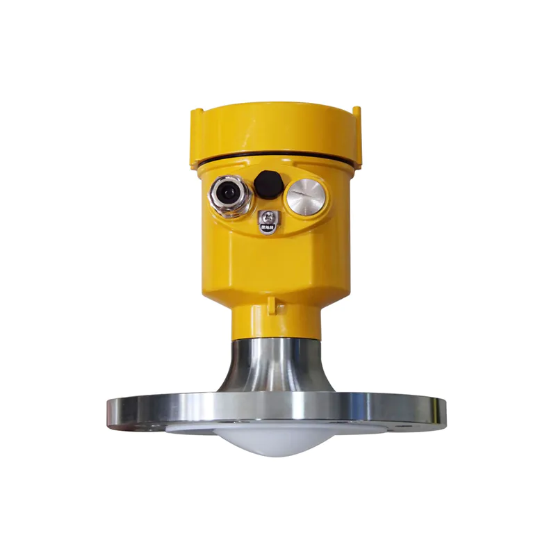
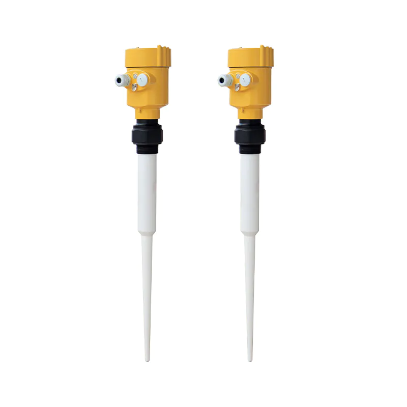
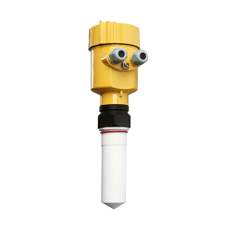
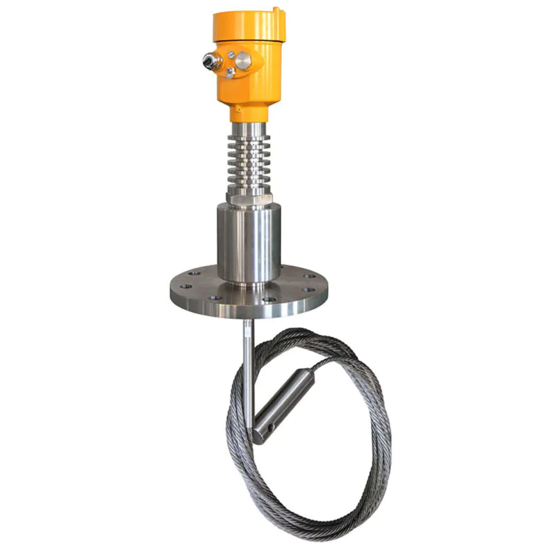
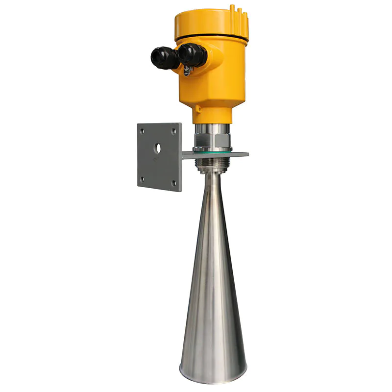
 Measuring medium: solid
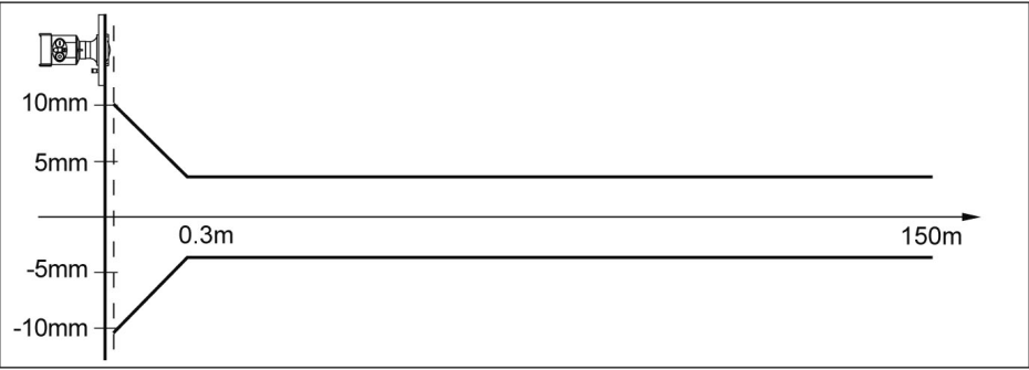
Measuring range: 0.3m~150m
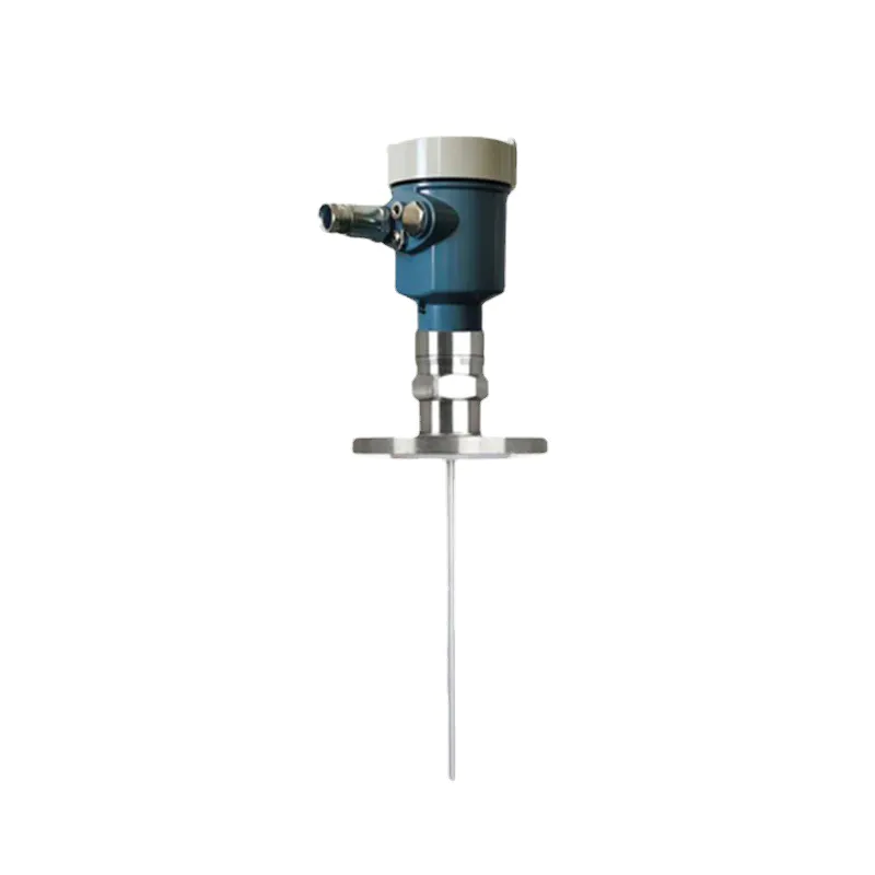
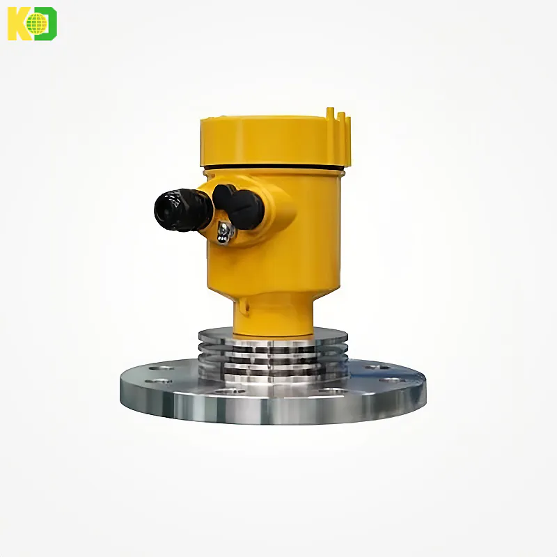
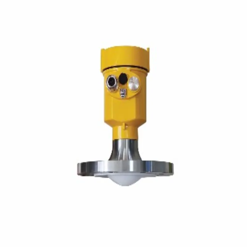
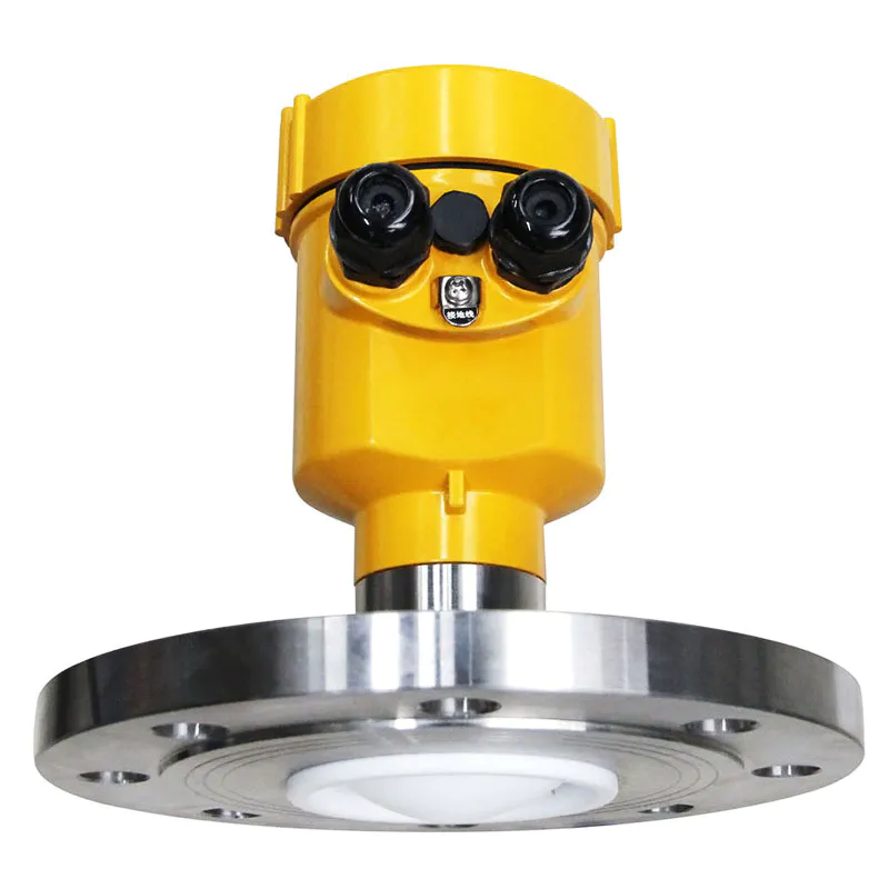
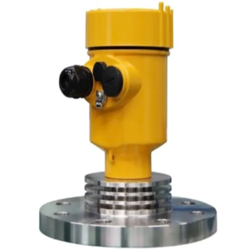
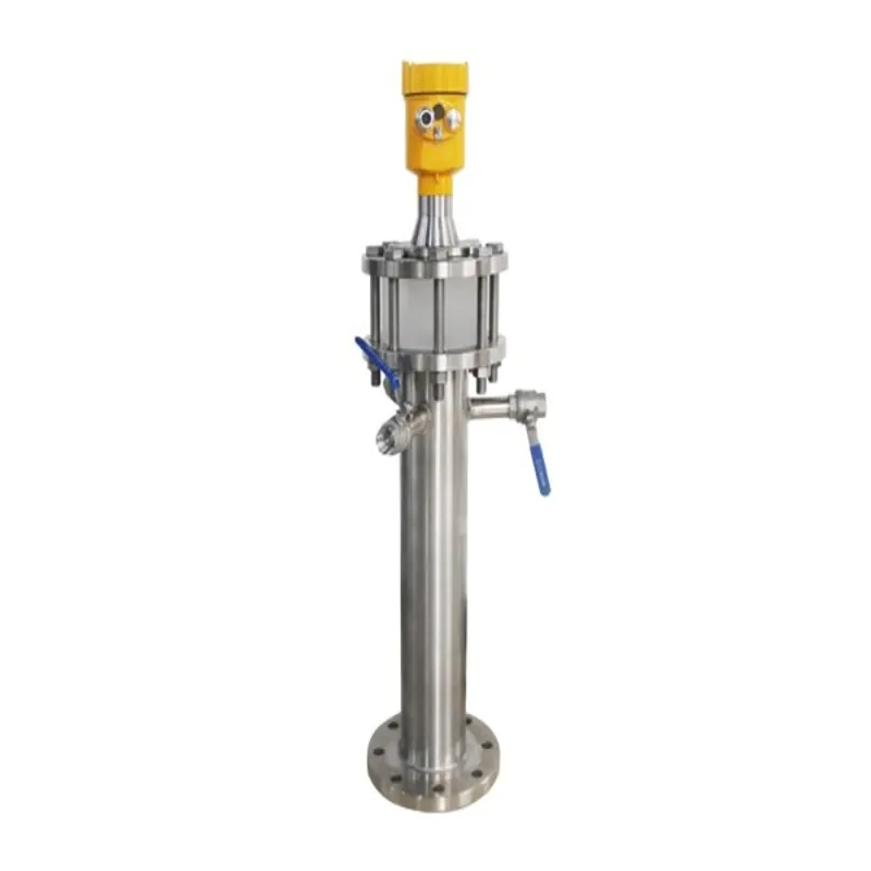
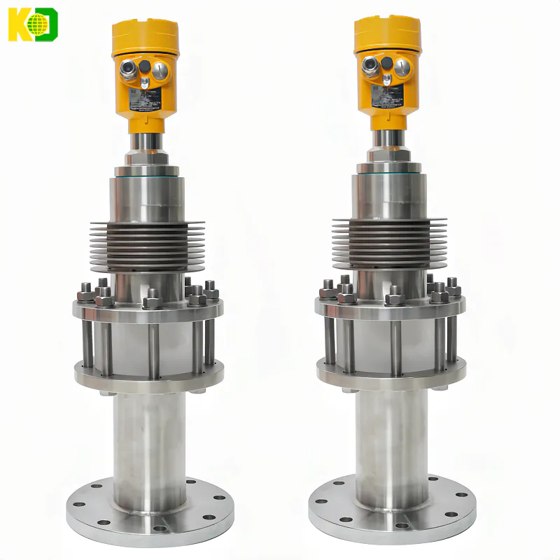
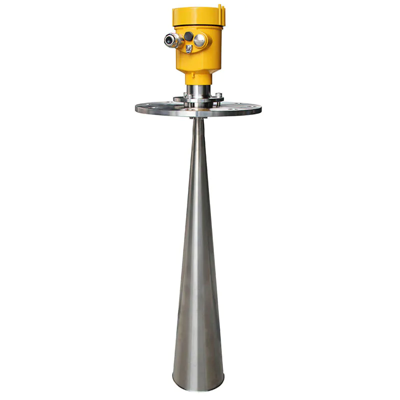
Process connection: flange ≥DN80
Process temperature: -40~110℃
Process pressure: -0.1~0.3MPa
Precision: ±5mm
Protection level: IP67
Frequency range: 123GHz
Power supply: two-wire system (DC24V)/four-wire system (DC12V~24V)/four-wire system (AC220V)
Explosion-proof grade: Exia ⅡC T6 Ga / Exd IIC T6 Gb
Shell: Aluminum/Plastic/Stainless Steel
Signal output: two-wire system 4...20mA/HART protocol/four-wire system 4...20mA /RS485 Modbus
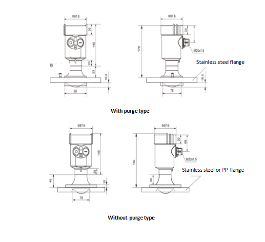
| Process connection | Flange | |||
| Material | 304 stainless steel, PP | |||
| Shell | Seal between housing and housing | Silicone Rubber | ||
| Shell window | Polycarbonate | |||
| Ground terminal | Stainless steel | |||
| Supply voltage | Four-wire system | Standard | (12~24)V DC | |
| Power consumption | max80mA DC24V/2W | |||
| Allow ripple | <100Hz | Uss<1V | ||
| (100~100K)Hz | Uss<10mV | |||
| Double chamber housing | (198~242)V AC | Four-wire system | ||
| 100V AC | Four-wire system | |||
| Cable parameters | Cable entry/plug | 1 M20x1.5 cable entry | ||
| 1 blind plug M20×15 | ||||
| Ground terminal | Conductor cross section 2.5mm2 | |||
| Output parameters | output signal | (4~20)mA/RS485Modbus | ||
| Resolution | 1mm | |||
| Fault signal | Current output unchanged; 20.5mA; 22mA; 3.9mA | |||
| Integration time | (0~20)s, adjustable | |||
| Blind spot | 0.1m/0.2m/0.3m | |||
| Maximum measurement interval | 150 meters | |||
| Measuring distance | About 1 second (depending on parameter settings) | |||
| Adjust the time | About 1 second (depending on parameter settings) | |||
| Adjust time, working storage and transportation temperature | (-40~80)℃ | |||
| Process temperature | KD-FMF11 | -40~80℃ | ||
| KD-FMF12 | -40~110℃ | |||
| KD-FMF13 | -40~110℃ | |||
| KD-FMF15 | -40~200℃ | |||
| KD-FMF21 | -40~110℃ | |||
| Relative humidity | <95% | |||
| Pressure | Max2.5MPa | |||
| Shockproof | Mechanical vibration 10m/s2, (10~150)Hz | |||
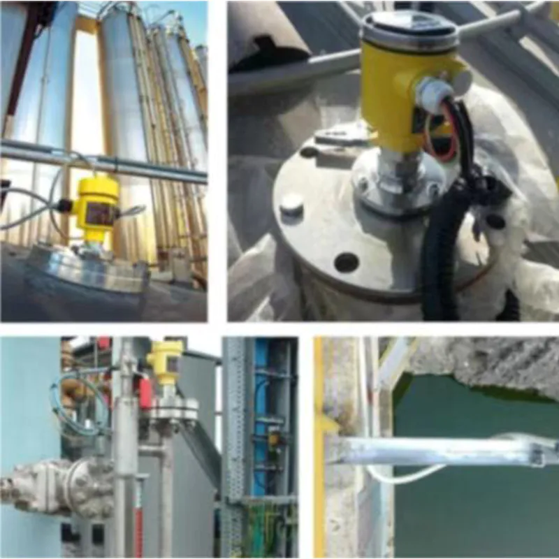
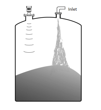
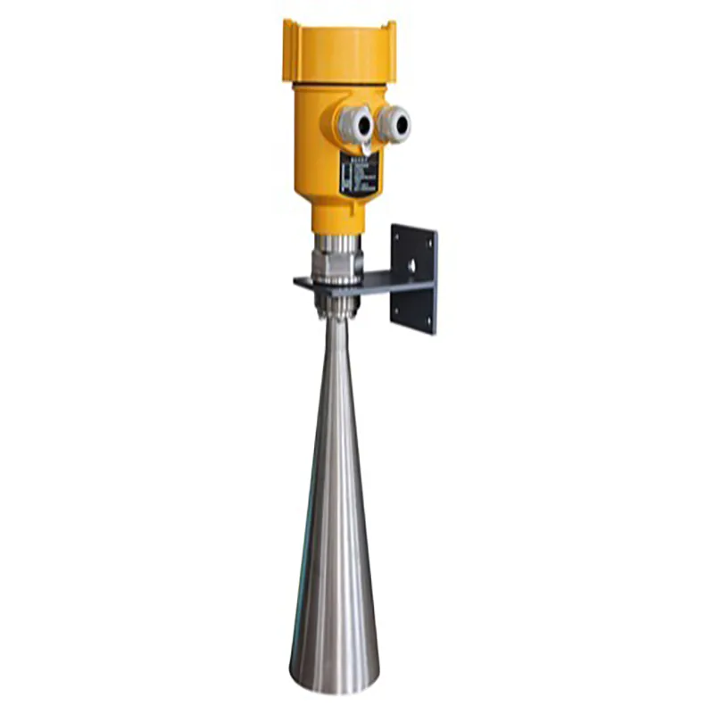
When installing the instrument, avoid installing it above the inlet, and try to avoid all kinds of objects that affect the signal, such as stirring paddles, etc.
● Under extremely complicated working conditions, the instrument can work normally if there is no obstacle in the area of 500px radius with the radar installation point as the center.
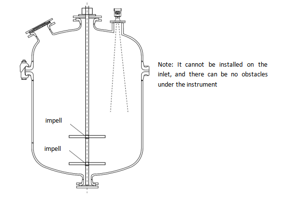
Can not be installed above the inlet, and there should be no obstacles under the instrument
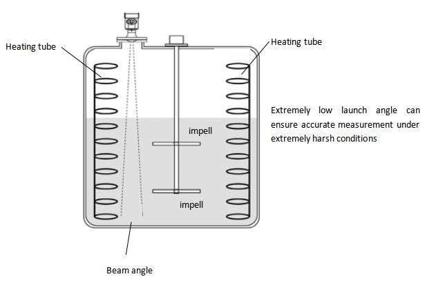
Under extremely complicated working conditions, the instrument can work normally if there is no obstacle in the area of 500px radius with the radar installation point as the center.
We are here to help you! If you close the chatbox, you will automatically receive a response from us via email. Please be sure to leave your contact details so that we can better assist


![kaidi KD-906 26G Radar Level Meter [Anti-corrosion] High Temperature Intelligent](https://img80003270.weyesimg.com/uploads/kaidi86.com/images/16760218661446.jpg?imageView2/2/w/1920/q/80/format/webp)


![kaidi KD-802 6G Radar Level Meter [Anti-corrosion Type]](https://img80003270.weyesimg.com/uploads/kaidi86.com/images/15936739299092.jpg?imageView2/2/w/1920/q/80/format/webp)
![kaidi KD-FMF15 FM radar level meter [chemical and electric power industry]](https://img80003270.weyesimg.com/uploads/kaidi86.com/images/15936722293812.jpg?imageView2/2/w/1920/q/80/format/webp)