

1.Product introduction
The magnetic column level gauge uses the principle of buoyancy and magnetic coupling to linearly transmit the change of the liquid level to the indicator, clearly indicating the height of the liquid level. The indicator and the storage tank are isolated, so use is guaranteed. The liquid level gauge can also be equipped with a liquid level alarm switch and a liquid level remote transmitter. Liquid level alarm switch can realize liquid level up and down control, limit alarm and interlock; liquid level remote transmitter can linearly convert liquid level change into DC 4-20mA output, realize remote liquid level indication, detection, Control and record
2.The main technical parameters
Measuring range: 0 ~ 12m
Indication accuracy: ±10mm
Working pressure: 1.0 ~ 6.4MPa
Working temperature: -20 ~ 350℃
Medium density: ≥0.45g/cm³
Medium density difference: ≥0.15g/cm³ (measurement interface)
Medium viscosity: ≤0.15Pa .S
Wetted material: 1Cr18Ni9Ti, SUS304, SUS316, SUS316L, titanium, PVC, PP, FRP
Connection flange: pressure ≤2.5MPa JB/T81-94 PN2.5 DN20 pressure ≥2.5MPa JB/T82.2-94 PN6.4 DN20 (or as required by the user)
Sewage takeover: ZG1/2 "(inside)
3.Principle
The magnetic turning column level gauge is composed of float, riser assembly and indicator. The float rises or falls with the change of the liquid level in the riser assembly. Through magnetic coupling, the indicator color outside the riser assembly is driven to change (liquid red and gas white), thereby indicating the height of the liquid level. The liquid level alarm switch is installed at the corresponding alarm position outside the riser assembly. When the float reaches the alarm position with the liquid level, the alarm switch closes and sends out a switch signal; the liquid level remote transmitter is also installed outside the riser assembly and passes The magnetic coupling linearly converts the change of the liquid level into a 4-20mA current signal and transmits it to the control room to realize the display, measurement , control and recording of the liquid level.
4. Use and maintenance
☆ Make the display all white before using the flop. The installation and connection of the main pipe of the magnetic flap level gauge must be kept vertical. The flange on the level gauge and the flange on the container are connected and fixed with bolts, nuts and gaskets, and the container valve can be opened to slowly enter the liquid. For example, there is a shut-off valve between the instrument flange and the container flange, which is very good to use , It is convenient to disassemble and repair the level gauge.
☆ Check regularly during use to check whether the connection of each part of the level gauge is loose.
☆ After the magnetic flap level gauge is put into operation, it should be ensured that the liquid level in the storage tank changes smoothly, and the liquid level cannot rise or drop rapidly, causing the turning column to fail or upset. (If this phenomenon occurs, you can use the calibration magnet to recalibrate ).
☆ When using for a long time, check the corrosion of the parts regularly.
☆ For the level gauge installed on the device, it should be strictly checked before operation whether each part of the meter head meets the technical requirements, and if any problems are found, they should be dealt with in time.
☆ Precautions for explosion-proof installation and use
☆ The selection, installation and maintenance of explosion-proof level gauges must be carried out in accordance with the "Electrical Regulations for Explosive Hazardous Locations of the People's Republic of China".
☆ The internal and external locations of the junction box must be firm and reliable.
☆The electrical wiring gap and creepage distance must be greater than 10mm.
☆ For maintenance, the power supply must be cut off and the cover must be opened. During disassembly, avoid damage to the explosion-proof surface. After maintenance, the lead wires and the meter cover must be locked to prevent slippage.
☆ The explosion-proof surface should not be painted, but should be painted with anti-rust paint.
☆ The level gauge should be placed under normal temperature and dry air.
☆ Make the display all white before using the flop. The installation and connection of the main pipe of the magnetic flap level gauge must be kept vertical. The flange on the level gauge and the flange on the container are connected and fixed with bolts, nuts and gaskets, and the container valve can be opened to slowly enter the liquid. For example, there is a shut-off valve between the instrument flange and the container flange, which is very good to use , It is convenient to disassemble and repair the level gauge.
☆ Check regularly during use to check whether the connection of each part of the level gauge is loose.
☆ After the magnetic flap level gauge is put into operation, it should be ensured that the liquid level in the storage tank changes smoothly, and the liquid level cannot rise or drop rapidly, causing the turning column to fail or upset. (If this phenomenon occurs, you can use the calibration magnet to recalibrate ).
☆ When using for a long time, check the corrosion of the parts regularly.
☆ For the level gauge installed on the device, it should be strictly checked before operation whether each part of the meter head meets the technical requirements, and if any problems are found, they should be dealt with in time.
☆ Precautions for explosion-proof installation and use
☆ The selection, installation and maintenance of explosion-proof level gauges must be carried out in accordance with the "Electrical Regulations for Explosive Hazardous Locations of the People's Republic of China".
☆ The internal and external locations of the junction box must be firm and reliable.
☆ The electrical wiring gap and creepage distance must be greater than 10mm.
☆ For maintenance, the power supply must be cut off and the cover must be opened. During disassembly, avoid damage to the explosion-proof surface. After maintenance, the lead wires and the meter cover must be locked to prevent slippage.
☆ The explosion-proof surface should not be painted, but should be painted with anti-rust paint.
☆ The level gauge should be placed under normal temperature and dry air.
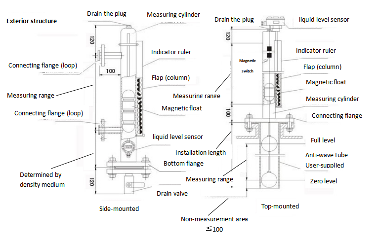
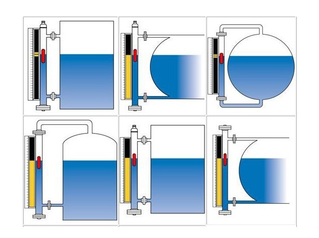
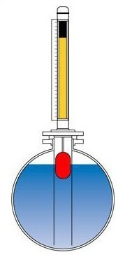
5.Outline structure and installation diagram


Product accessories
☆ After the user receives the package, first check whether the package is complete.
☆ Supplied accessories: Qualification certificate, instruction manual
6.Order Information
When ordering, please indicate product specifications, measurement range, measured medium density, working pressure, standard specifications of connecting flanges, material requirements, etc. If you have special orders, please negotiate face-to-face.
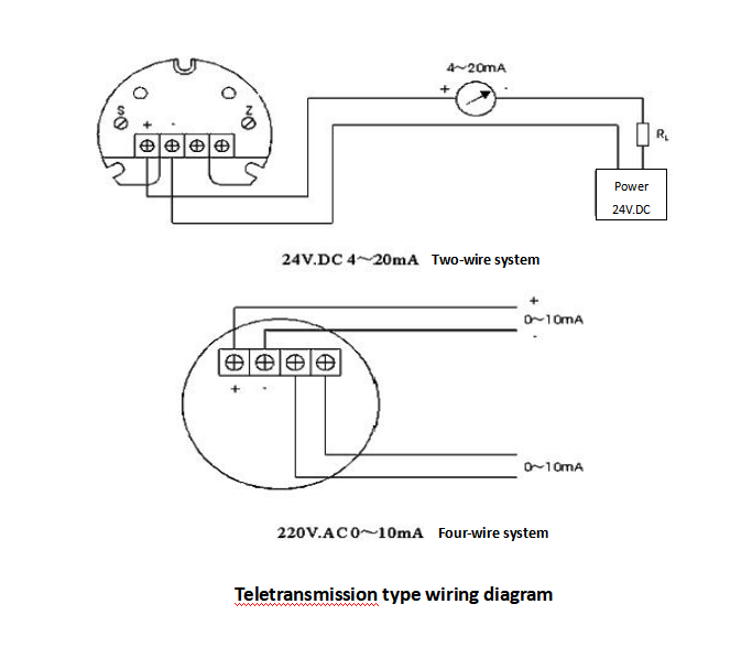
Note: If equipped with remote transmission and alarm switch wiring diagram

As follows:
When equipped with remote transmission supporting instrument (transmitter or liquid level controller), the following items need to be done:
(1) The remote transmission supporting instrument should be close to the tube of the level gauge and fixed with a stainless steel hoop. (Iron is prohibited).
(2) The green sensing surface mark on the remote transmission supporting instrument should face and be close to the main pipe body of the level gauge.
(3) The red zero mark on the remote transmission supporting instrument should be on the same horizontal line as the zero indication of the level gauge.
(4) The connection between the remote transmission supporting instrument and the display instrument or industrial computer shall be laid separately through a protective tube or with a shielded two-core cable. The shield can only be grounded at one end, and the cross-sectional area of the wire diameter shall not be less than 0.8mm2
(5) After the wiring hole of the junction box is tied, it is required to be well sealed to prevent rain, moisture, etc. from intruding and causing the remote transmission instrument to fail to work normally. The junction box should be opened during maintenance and debugging, and should be closed in time after completion.
Please Send Us your Application details
Measuring range , medium, Installation method (flange, thread), Pressure range, Remote transmitter, Level alarm switch
More Model available for all appication, different termperture and pressure!
We are here to help you! If you close the chatbox, you will automatically receive a response from us via email. Please be sure to leave your contact details so that we can better assist
Our technical team will check your specifications and make a best solution for you.