 Español
  pусский
  العربية
  Português

Kaidi KD UQD Intelligent Large Float Level Transmitter IP67 for chemical industry


Product Overview
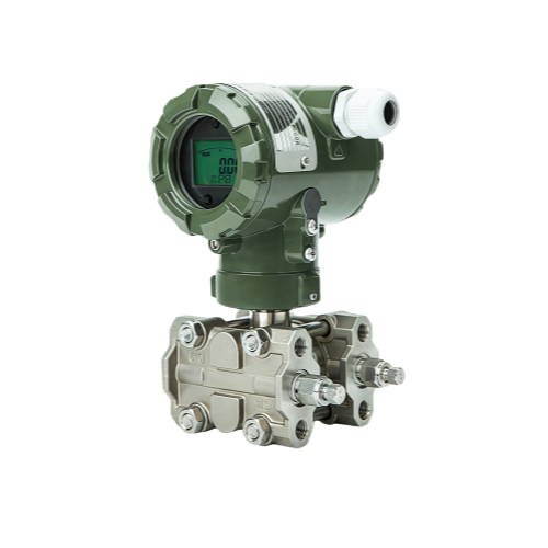
kaidi KDT800-4051DRpressure/differential pressure transmitter adopts the microprocessor as the core in the circuit design and supports the modular design with the advanced digital isolation technology, which makes the instrument have high anti-interference and stability. At the same time, the transmitter is compensated by the built-in temperature sensor, which improves the measuring accuracy, reduces the temperature drift, has the characteristics of good long-term stability, high reliability and strong self-diagnosis ability. In the structure, the user can easily calibrate, set and configure the transmitter by HART operator.
Product Features
1. Advanced monocrystalline silicon pressure, differential pressure sensor technology and packaging technology, carefully developed a leading technology of ultra-high performance pressure, differential pressure transmitter
2. One-way overvoltage up to 25 MPa
3. The microprocessor is designed with advanced digital isolation technology, which makes the instrument have high anti-interference and stability
4. Powerful 24-bit ADC for High Precision
5. The latest one-click zero-clearing function does not affect the level of electrical protection, more safe and faster.
Technical parameters
Measuring media: gas, steam,
liquid Inaccuracy:±0.05%,±0.075%,±0.1%(including linearity, return and repeatability from zero)
Stability:±0.1%/3 years
Ambient temperature effect:≤±0.04% URL/10℃
Static pressure effect:±0.05%/10MPa
Power supply:15~36VDC
Power effect:±0.001%/10V, negligible
Ambient temperature:-40℃ ~85℃
Measured medium temperature:-40℃ ~120℃
Storage temperature:-40℃ ~85℃
Show: LCD
Display module temperature:-20℃~70℃

Power supply voltage and external load diagram
Size and Weight of Transmitter
Outline dimension


Differential pressure transmitter dimension


Pressure Transmitter Size Chart
Weight
Differential pressure transmitter :2.8Kg Pressure transmitter :1.1Kg
Transmitter installation
Differential pressure transmitter installation
The differential pressure transmitter can be mounted directly on the 2 inch tube or directly on the wall as well as on the dashboard.

Pipe mounting bracket

Plate bending bracket

Pipe leveling support
Differential pressure transmitter

Welded pipe joints Waist flange

T-joint Three Valves Section
Installation of three valve groups: The three valve groups are installed to close the high and low end valves on both sides, open the middle balance valve, and after the differential pressure transmitter is cleared, open the high and low end valves on both sides to close the middle balance valve. Remove differential pressure transmitter: First open the middle balance valve, close the two sides of the high and low end valve middle balance valve open, you can remove the differential pressure transmitter.
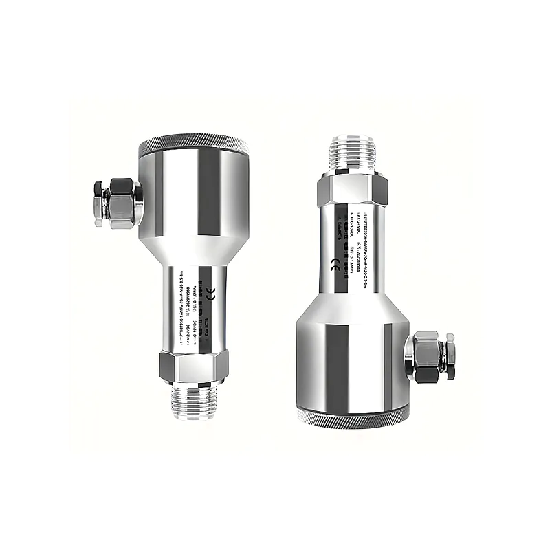
Pressure transmitter installation
The pressure transmitter can be mounted directly on the pipe using M20*1.5 external threads or other threads, or through the pressure pipe and bracket mounting.

Pressure pipe installation
The pressure introduction angle in the process is shown below:

Pressure introduction angle
When measuring the gas medium, the inductor pressure pipe shall be installed in the range of 45° vertical upward and both sides, and the transmitter shall be installed above the side pressure extraction port for liquid to be discharged into the process pipe. When measuring the steam medium, the pressure pipe should be installed in the range of 45° above the horizontal direction, and the transmitter should be installed under the side pressure extraction port so that the condensate can flow into the pressure pipe. It should be noted that when measuring steam or other high temperature media, it should not exceed the limit temperature of the transmitter. When measuring the liquid medium, the induced pressure pipe shall be installed in the range of 45° below the horizontal direction, and the transmitter shall be installed under the side pressure extraction port for the gas to be discharged into the process pipe. Use a transmitter with an exhaust/exhaust valve on the side. The pressure 9outlet should be mounted on the side of the process pipe. When the working medium is liquid, the exhaust / drain valve is installed in the upper part of the flange to discharge the gas; when the working medium is gas, the exhaust / drain valve is installed in the lower part of the flange to discharge the liquid. Flange level transmitter installation

Installation of remote flange pressure/differential pressure transmitter

Electrical connection of transmitter
Second Line Terminal

① Transmitter power supply
② Negative transmitter power
supply (4~20mA test terminal negative )
③ 4~20mA test terminal
④ Internal Grounding Screw
⑤ External earthing screws
4-wire terminal (RS485)

1 Transmitter power supply ② Negative transmitter power supply ③ RS485 Communication Port A ④ RS485 Communication Port B ⑤ Internal Grounding Screw ⑥ External earthing screws
2-wire power cord connection

Transmitter power connection diagram
Second Line Current Testing Instrument Connection

Transmitter power connection diagram
Second Line Hart Communication Connection

Hart Communicator Connection at Transmitter End

A computer or Hart communication device connected to a two-wire power supply
Four-line RS485 communication connection

Connection description of flameproof transmitter

Power connection diagram of explosion-proof transmitter
The structure and parts of the flameproof transmitter are strictly inspected and tested according to the flameproof explosion-proof standard, which conforms to GB3836.2-2010 Part 2: Equipment for the protection of the electrically insulated outer shell "d ", marked Exd IICT6Gb. Transmitter users should be reliably grounded in use, using an ambient temperature range of -20°C ~60°C. The flameproof transmitter should pay attention to the measures to protect the explosion-proof joint surface and explosion-proof when installed, the end cover must be rotated to the end and lock the anti-loosening device; the parts of the plane gap should prevent the plane collision and scratch to make the gap bigger when loading and unloading; the shell should prevent the collision and damage, so as not to reduce the strength; all the screws, housing and wiring after the instrument maintenance inspection must be fastened, cannot be damaged, or lose the explosion-proof performance. flameproof transmitter is strictly forbidden to open or loosen the end cap or shell under the condition of field electrification. One of the two outlet ports of the flameproof transmitter adopts the cable connection, and its cable joint adopts the special pressure nut type flameproof introduction device of our company. Hollow bolts, gaskets,sealing rubber traps on the outer diameter of the cable, the cable should choose the outer diameter of the cable 8mm, the mounting interface is tight, the sealing ring must be guaranteed to be tightly wrapped on the outer diameter of the cable, and the hollow bolts must be rotated above 6 wire buckles. Another outlet must also be fitted with a sealed rubber ring, solid bolts, solid bolts must be tightened, the screw must also be more than 6 threads.
Wiring instructions for explosion-proof transmitter

The connection diagram of the power cord of the explosion-proof transmitter

Ben'an wiring diagram
Explosion-proof safety performance conforms to GB3836.1-2010 Explosive Environment Part 1: General Equipment Requirements and GB3836.4-2010 Explosive Environment Part 4: Equipment protected by the intrinsically safe type "I ", the product explosion proof mark is Exia IICT4Ga. Ben'an parameter: Ui =28VIi =93mA Pi =0.65W Ci =52nF Li =138.6uH Transmitter users should be reliably grounded in use, using an ambient temperature range of -20°C ~60°C.This type of safety transmitter must be connected with the safety gate identified by the explosion-proof inspection organization when it is installed and used in the field. The safety grid must be placed in a non-hazardous location and its installation and use must comply with the instructions for the use of the safety grid. The connecting cable between transmitter and safety gate safety end is two core shielded cable (cable must have cable sheath). The cross section area of the core wire is more than 0.5 mm2, and its shield layer is grounded at the single end of the safe place and insulated from the product housing; the cable wiring should eliminate the influence of electromagnetic interference as much as possible, and the cable distribution parameters should be controlled within 0.06μF/1mH.
Key Instructions
Shell external one-click PV zero clearing function
The installation may result in a deviation of the measured value, which can direct the transmitter to the atmosphere and zero in the following 1,2 items without measuring the pressure. If the three valve groups are installed in the field, first close the high and low end valves on both sides, open the middle balance valve, the differential pressure transmitter press the following 1,2 items to clear zero, and then open the high and low end valves on both sides to close the middle balance valve. 1.explosion-proof products: screw the side screw of the shell with a screwdriver to loosen, spin the baffle, insert the magnetic rod into the bottom contact, protect, Hold for more than 10 seconds, display to zero and then take out the magnetic rod, then put the gear back to tighten. 2.Non-explosion-proof products: unscrew the display cover, press the Z key for 10 seconds, the display becomes zero before loosening the button.

Basic mode of key operation
1.Hold down the M key continuously for 5 seconds, enter the key setting mode; 2.After entering the first display is the various settings menu, press S key or Z key to achieve menu up and down; 3.When you find the page you need to set, press and hold the M key for 2 seconds to enter the menu settings. 4.In the Settings menu, hold down the S or Z keys to implement the up and down of the options. (Head button diagram).

Key to modify menu data operation
1.Positive and negative sign setting: When the number of symbols is set, the symbol bit flashes; when the number is negative, the "-" flashes; when the number is positive, the "▲;" flashes; hold down the S key to switch, hold down the Z key to confirm the saving symbol. Then the cursor switches to the first digital flicker. 2.Digital modification: After entering the menu, in the menu that needs data modification, holding down the S key when the number flashes can be accumulated from the "0-9" cycle, holding down the Z key to confirm the save. Note: Digital modification must not exceed the upper and lower limits of the range, otherwise the setting is not successful. 3.Decimal point setting: hold down the s key when the decimal point after the number flashes; hold down the m key setting successfully when the next number flashes, otherwise the setting is not successful. Note: The decimal point setting must not exceed the upper and lower limits of the range, otherwise the setting is not successful.
Combination button operation
1.Zero point migration: apply zero point pressure to the sensor at the same time hold down the M key and Z key for 5 seconds, the display below the display screen ZERO
display screen starts to flicker, when the display screen central display SAVE operation is completed, release the key. 2.Full migration: apply full pressure to the sensor and hold down the M and S keys for 5 seconds. The bottom of the display screen starts to flicker. When the center of the display screen shows SAVE, loosen the button 。

Key function table

Operation instructions for keys of the safety explosion-proof transmitter
PV zero and high and low point fine-tuning settings

General parameter settings

Restoration of factory settings

Please Send Us your Application details
Measuring range , medium, Installation method (flange, thread), Pressure range, Remote transmitter, Level alarm switch
More Model available for all appication, different termperture and pressure!
We are here to help you! If you close the chatbox, you will automatically receive a response from us via email. Please be sure to leave your contact details so that we can better assist


Our technical team will check your specifications and make a best solution for you.