 Español
  pусский
  العربية
  Português
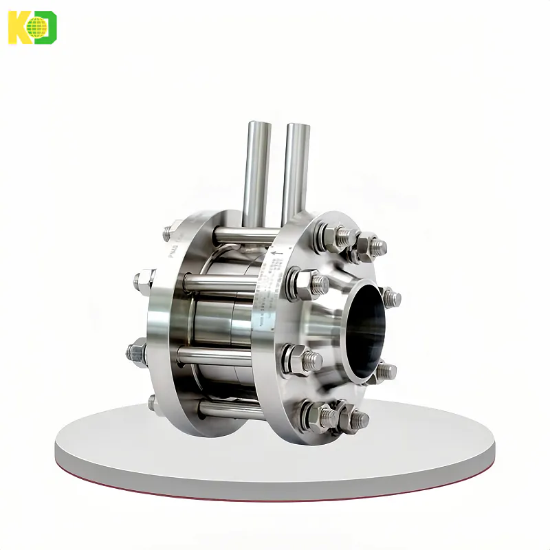
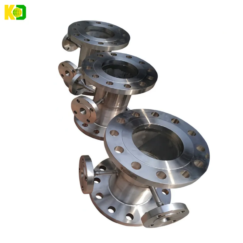
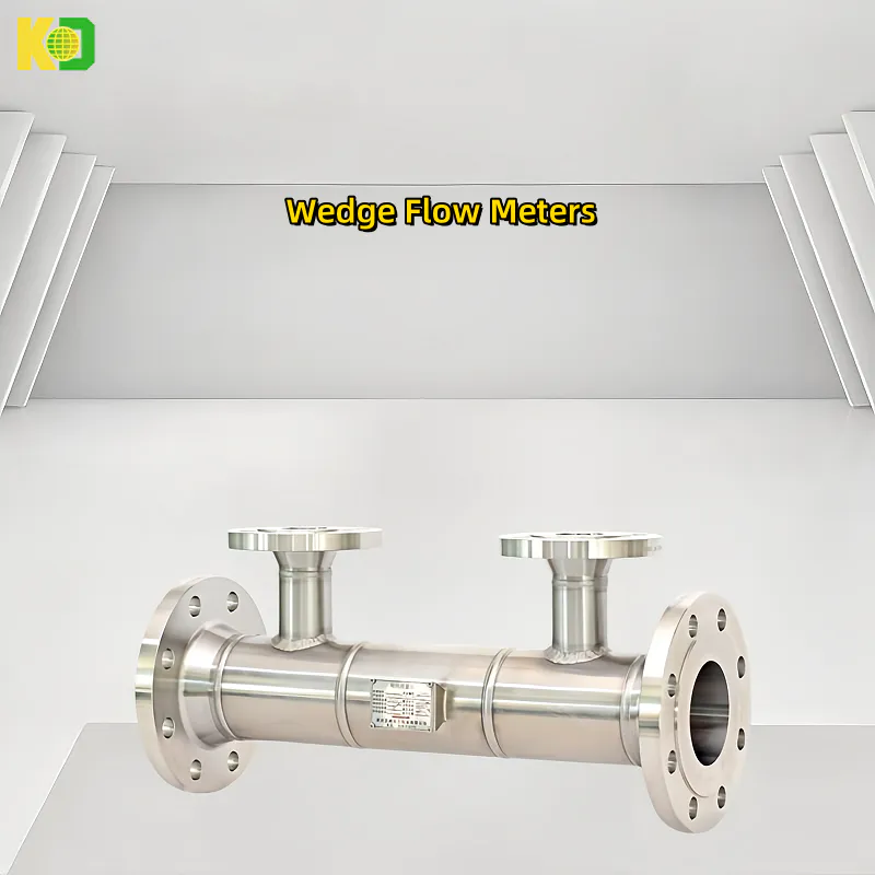
Kaidi KD YELJZ Standard Long Diameter Nozzle Flowmeter Integrated Differential Pressure Throttling Device High Temperature Steam Nozzle Flowmeter


APPLICATION
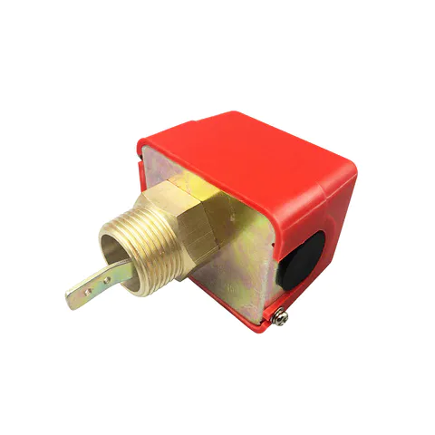
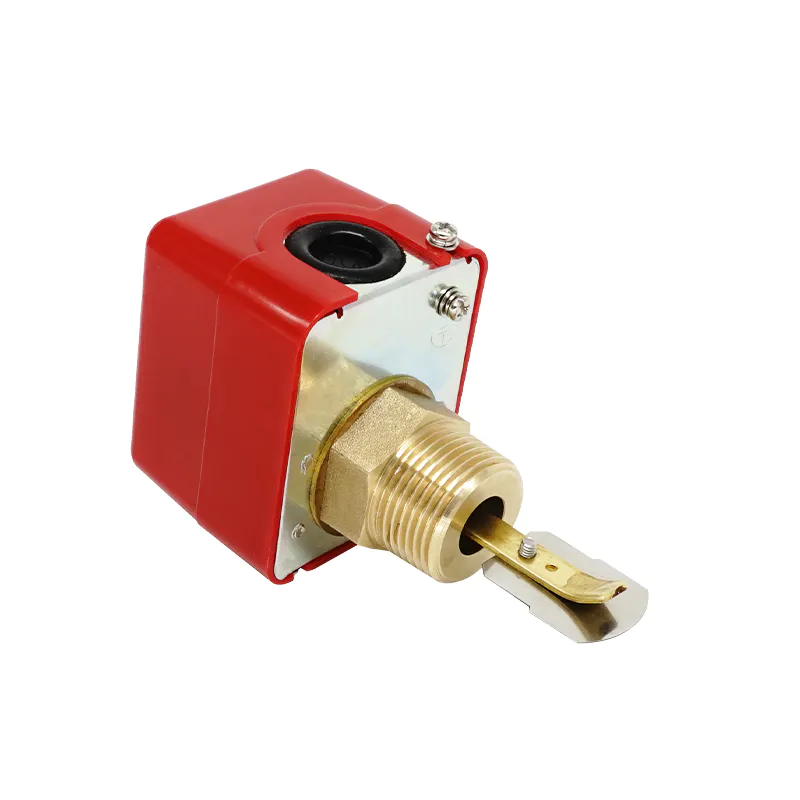
The paddle type SPDT KFS25 series are designed to provide excellent performance where accuracy, reliability, and rugged construction (IP54) are required used in liquid flow lines carrying water or any fluid neither harmful to brass and phosphor bronze nor classified as a hazardous fluids.
They can be wired to close one circuit and open a second circuit when liquid flow either exceeds or drops below the adjusted flow rate.
The KFS25 series are recommended for liquid pressure and temperature as mentioned below and must not be used on lines carrying liquids below 0 degree C.
These series may be used on liquids with high salt or chlorine content but is not for use in hazardous atmospheres.
They may be also used outdoors but must be protected from weather or splashing water.
All series KFS25 flow switches are designed for use only as operating controls.
Where an operating control failure would result in personal injury and/or loss of property, it is the responsibility of user to add safety devices that protect against, or supervisory systems that warn of control failure.
Electrical ratings:
Type | Voltage | Resistance Load | Lamp Load | Motor Load |
AC (Standard) | AC 125 V | 5A | 44A | 5A |
DC | DC 115 V | 0.3A |
|
Specification:
Operating Pressure | 10kgf/cm² (1MPa) |
Withstand Pressure | 17.5Kgf/cm² (1.75MPa) |
Insulation Resistance | Over 100Ω, DC500VM |
Withstand Voltage | AC1500V/1minute |
Contact Point Life | 1000K Cycle |
Bellows Life | 500K Cycle |
Temperature Of Fluid | Max 100°C (212°F) |
Flow control range table:
CLASSIFICATION | FLOW CONTROL RANGE | LPM (GPM) | |||
Pipe Diameter (inch) | Paddle | Minimum | Maximum | ||
On-Flow | Off-Flow | On-Flow | Off-Flow | ||
1 | 1 | 15 (4.0) | 8 (2.0) | 45 (12.0) | 41 (11.0) |
1-1/4 | 26 (6.9) | 13 (3.4) | 75 (20.0) | 68 (18.0) | |
1-1/2 | 29 (7.0) | 20 (5.3) | 105 (28.0) | 94 (25.0) | |
2 | 2 | 34 (9.0) | 17 (4.5) | 120 (32.0) | 105 (28.0) |
2-1/2 | 60 (16.0) | 34 (9.0) | 210 (55.0) | 188 (50.0) | |
3 | 3 | 68 (18.0) | 30 (8.0) | 288 (76.0) | 275 (73.0) |
4 | 128 (34.0) | 64 (17.0) | 412 (109.0) | 360 (95.0) | |
5 | 225 (59.0) | 113 (30.0) | 750 (198.0) | 652 (172.0) | |
6 | 345 (91.0) | 172 (45.0) | 1125 (297.0) | 975 (258.0) | |
*This table illustrates the flow control range obtained from experimental data. A variation of up to 10% can be expected, depending on operating conditions. Final adjustments should be made on site using a flow meter | |||||
Please Send Us your Application details
Measuring range , medium, Installation method (flange, thread), Pressure range, Remote transmitter, Level alarm switch
More Model available for all appication, different termperture and pressure!
We are here to help you! If you close the chatbox, you will automatically receive a response from us via email. Please be sure to leave your contact details so that we can better assist


Our technical team will check your specifications and make a best solution for you.