Español
  pусский
  العربية
  Português
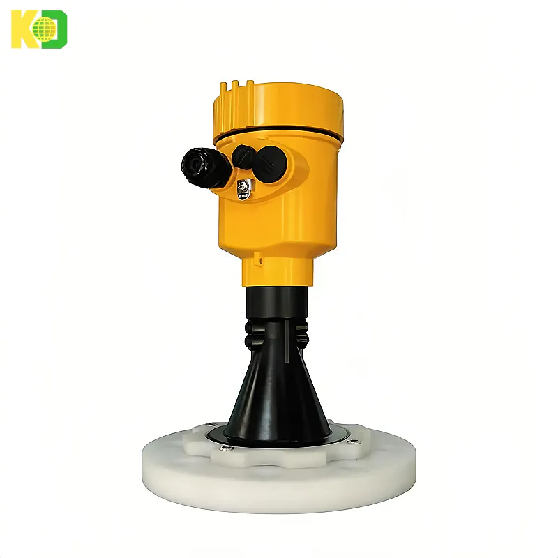
![kaidi KD-908S 26G Radar Level Meter [Anti-corrosion Type]](https://img80003270.weyesimg.com/uploads/kaidi86.com/images/16945046182991.png?imageView2/2/w/1920/q/80/format/webp)
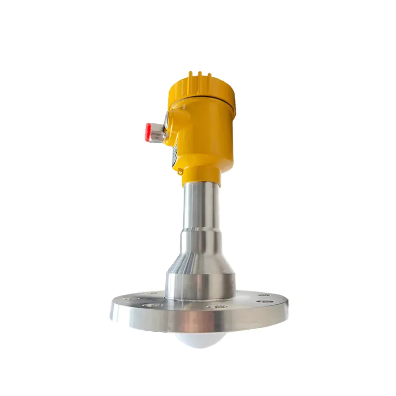
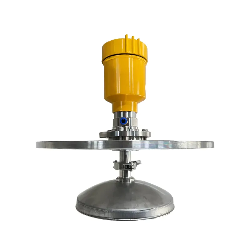
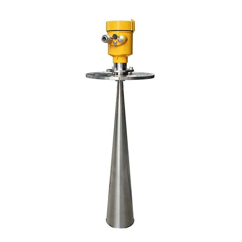
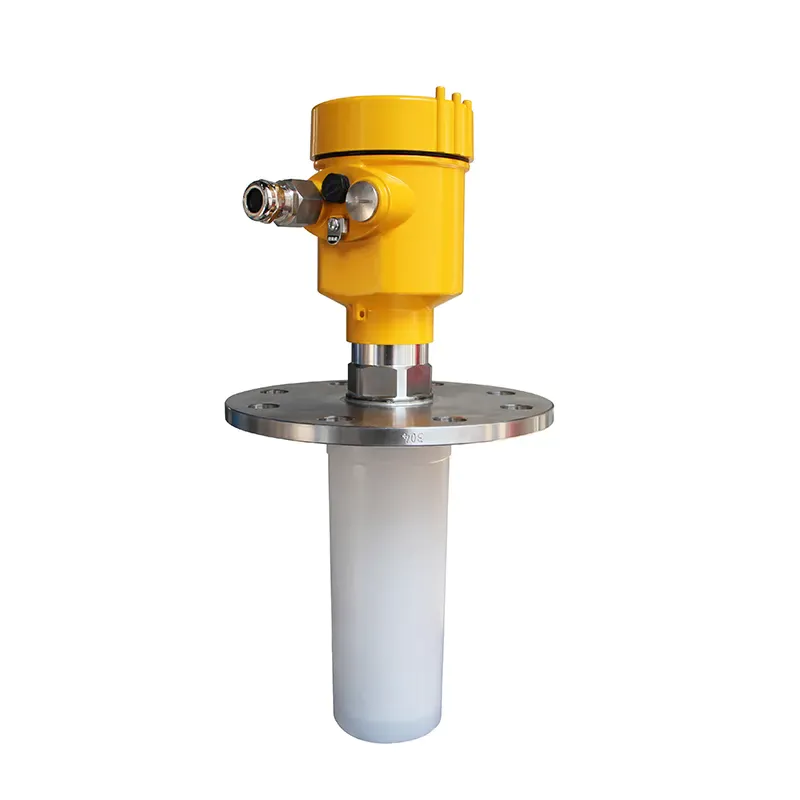
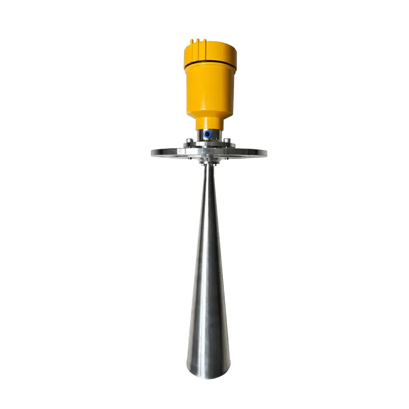
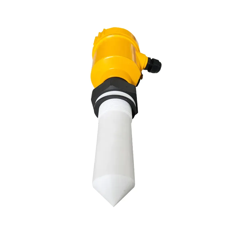
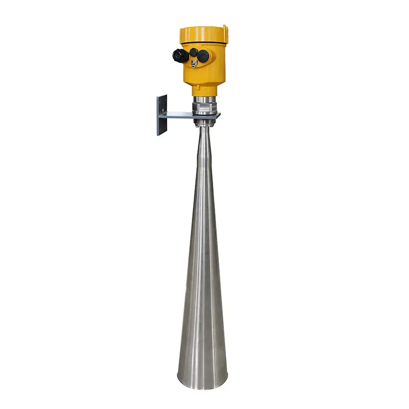
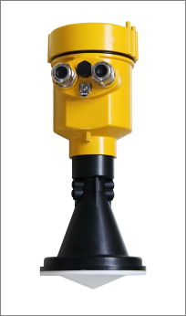
kaidi KD-908S 26G Radar Level Meter [Anti-corrosion Type]
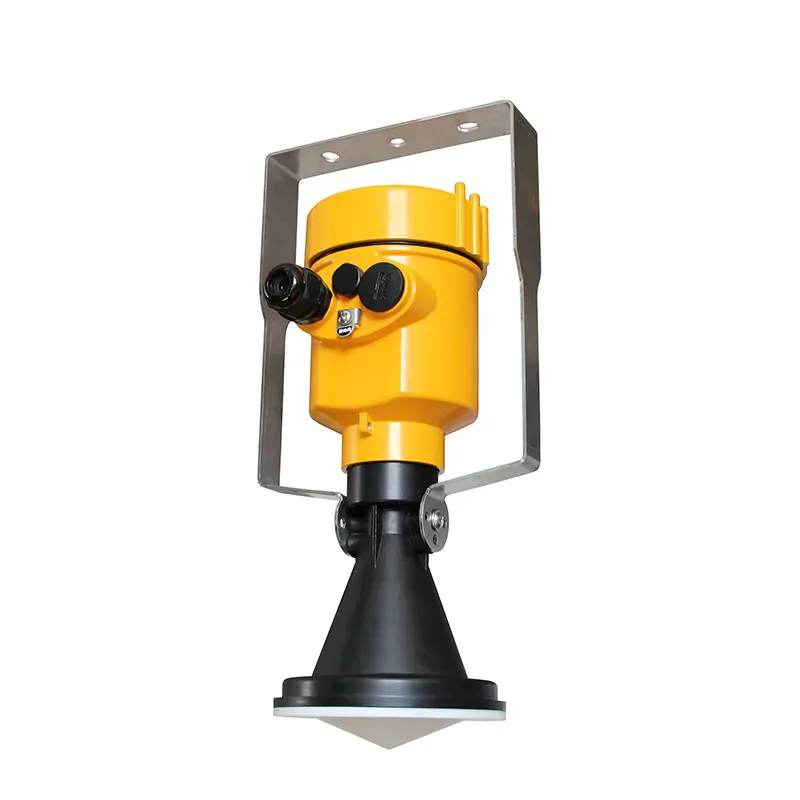
1. Product Overview
Principle
The radar water level antenna emits extremely narrow microwave pulses that travel at the speed of light, and part of the energy is reflected back when it encounters the surface of the measured medium and is received by the same antenna. The time interval between the transmitted pulse and the received pulse is proportional to the distance from the antenna to the surface of the measuring medium. Due to the extremely high propagation speed of electromagnetic waves, the time interval between the transmitted pulse and the received pulse is very small (nanosecond order) and it is difficult to confirm. The high-frequency radar water level gauge uses a special demodulation technology that can accurately identify the transmitted pulse and the received pulse The distance between the antenna and the surface of the measured medium can be further calculated.
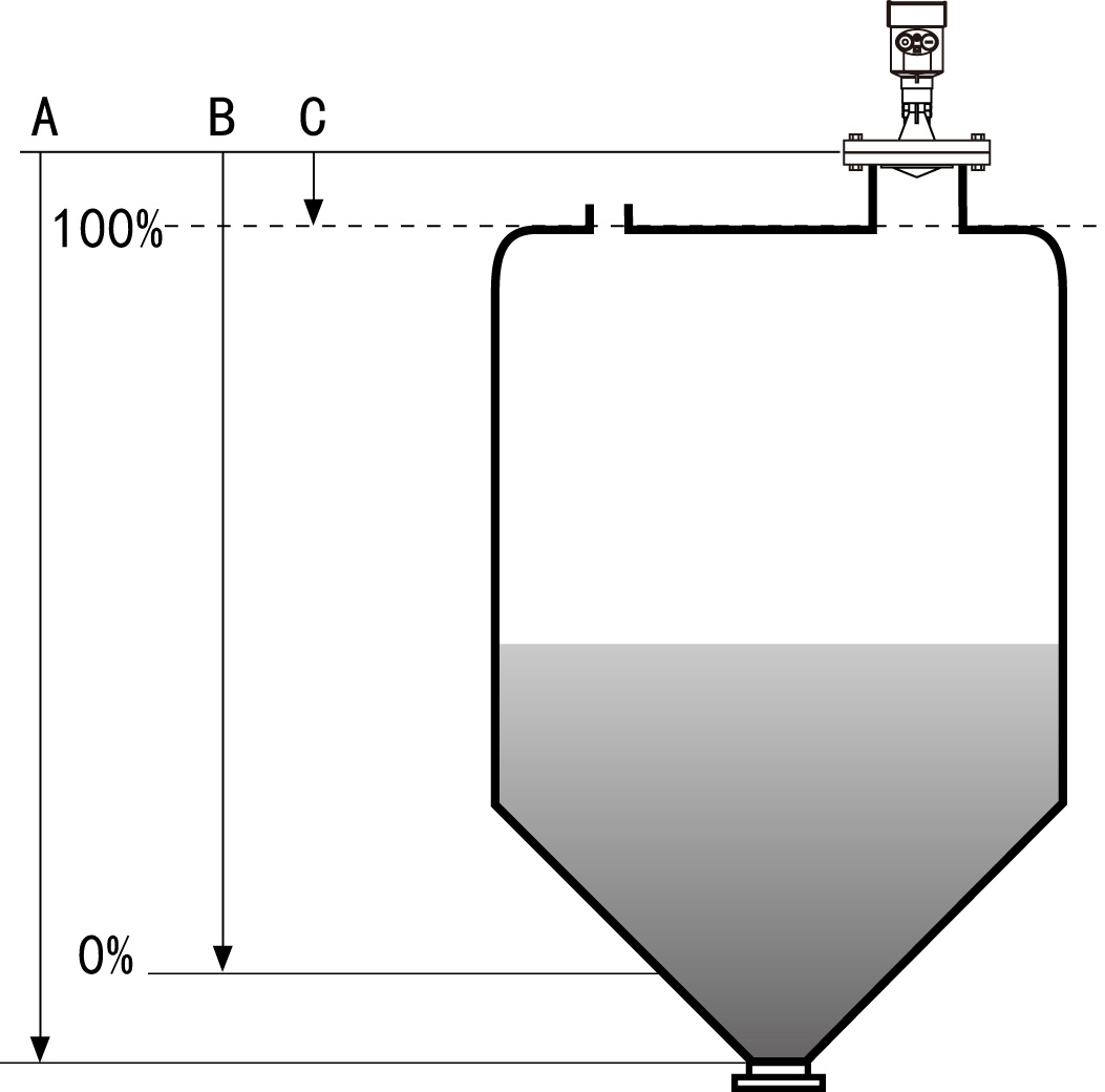
A Range Set
B Low Adjustment
C High Adjustment
Datum measurement: Screw thread bottom or the sealing surface of the flange
Note: Make sure the radar level meter the highest level cannot enter the measuring blind area.
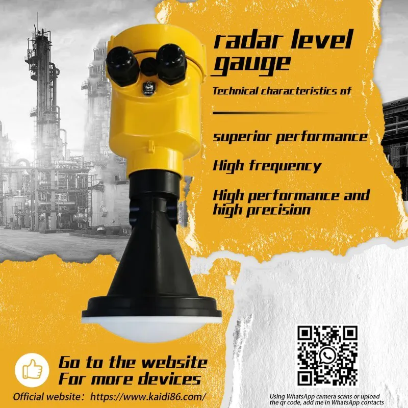
Application characteristics
The radar water level gauge uses a 26GHz transmitting frequency and has:
Ø Small beam angle, concentrated energy, stronger anti-interference ability, greatly improved measurement accuracy
Ø The antenna is small in size, easy to install, and easy to add dust cover and other antenna protection devices
Ø Lighter weight, about 1KG, easy to install
Ø The maximum measurement range can reach 70 meters, which can cover water level measurement such as large reservoirs
Ø With a variety of output circuit interface and data acquisition system.
Ø The pulse working mode, radar level meter transmit power is very low, no harm to human body and environment.
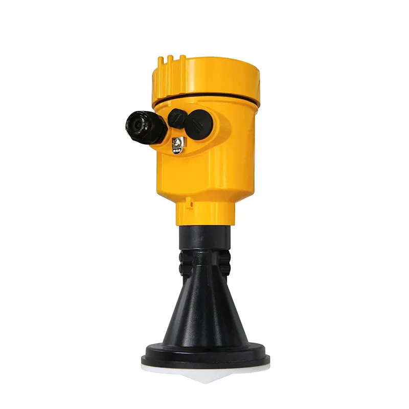
2. Product Introduction
908S
3.Instrument Installation
Installation Precautions:
Please pay attention to the following items to ensure that the meter can be installed correctly:
Please reserve enough space for installation.
Please avoid installation situations with strong vibration.
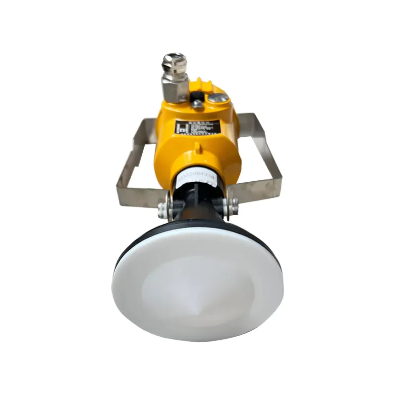
Illustration and installation position
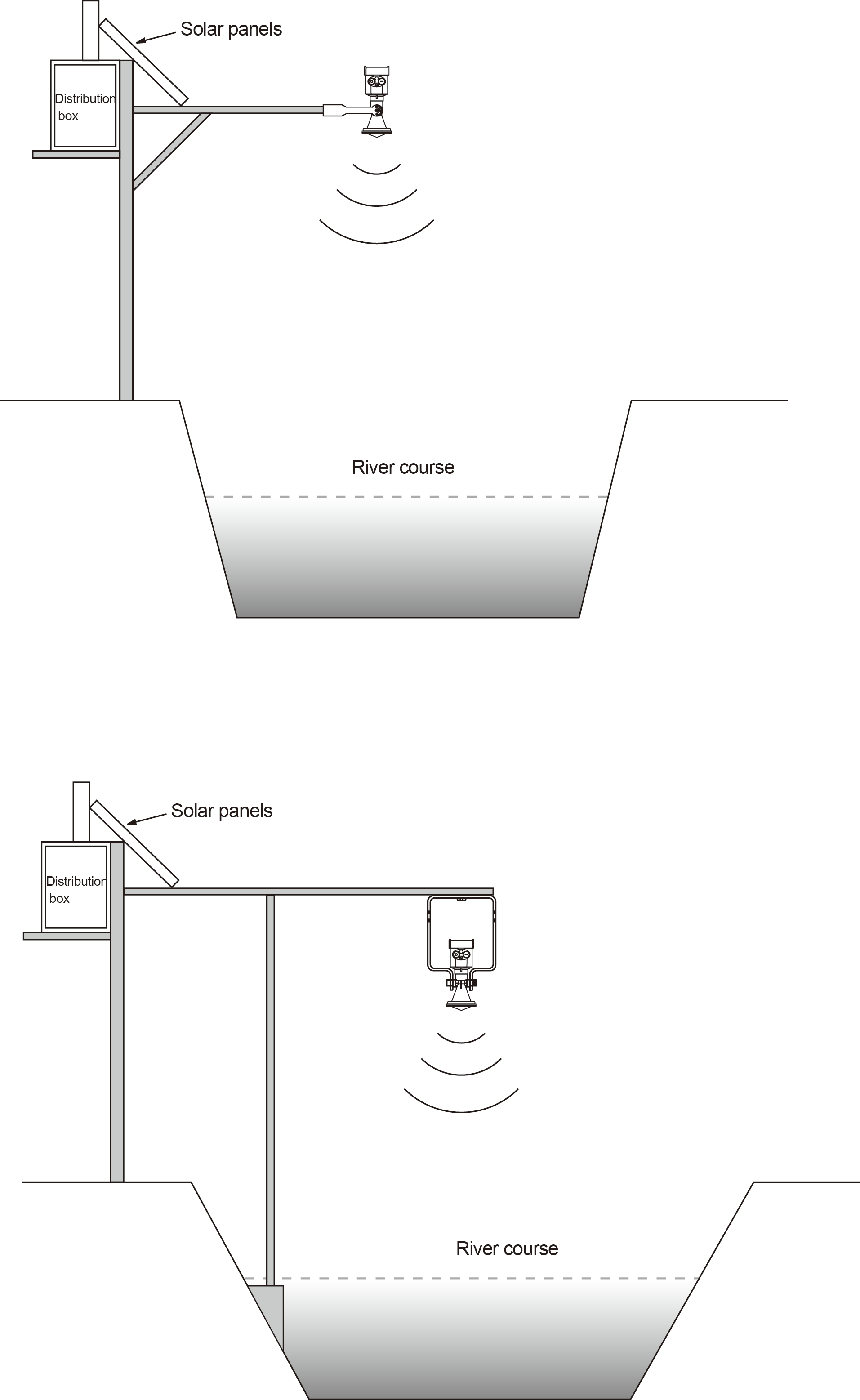
Radar and bracket installation diagram (1)
Radar and bracket installation diagram (2)
Note: When a radar antenna emits microwave pulses, it has a certain emission angle. There must be no obstacles from the lower edge of the antenna to the surface of the measured medium and in the area radiated by the emitted microwave beam. Therefore, shielding facilities should be avoided as much as possible during installation, and “false echo learning” must be carried out when necessary. When installing the instrument, also pay attention: the highest liquid level must not enter the blind area of the measurement; the instrument must be connected to the ground, and lightning protection measures shall be added; outdoor sun protection and rain protection measures shall be taken.
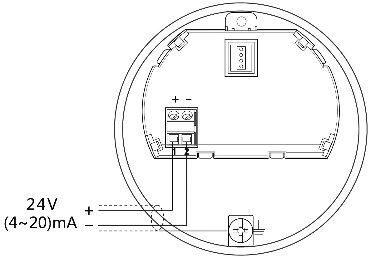
4. The Electrical Connection
The power supply voltage:
(4~20)mA/HART (Two wire system) | The power supply and the output current signal sharing a two core shield cable. The supply voltage range see technical data. For intrinsically safe type must be a safety barrier between the power supply and the instrument. |
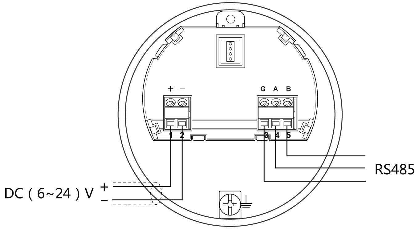
| Modbus - RS485 | Power supply and Modbus signal lines separated respectively using a shielded cable, the power supply voltage range of see technical data. |
Connection mode
Ø 24V two wire wiring diagram as follows:
Ø The Modbus-RS485 wiring diagram as follows:
Safety instructions:
Please comply with the requirements of local electrical installation regulations!
Please abide by the local regulations on personnel health and safety. All operations on the electrical components of the instrument must be completed by properly trained professionals.
Please check the nameplate of the meter to ensure that the product specifications meet your requirements. Please make sure that the power supply voltage is consistent with the requirements on the nameplate of the meter.
Protection grade:
This meter fully meets the requirements of protection class IP66/IP67, please ensure the waterproof characteristics of the cable seal. As shown below:
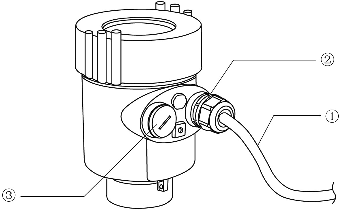
How to install to meet the requirements of IP67:
Please make sure that the sealing head is not damaged.
Please make sure that the cable is not damaged.
Please make sure that the cable for use with electrical connection specification.
Cable into the electrical interface before its curved downward, ensure that the water will not flow into the shell, see the①
Tighten the cable seal head, see the②
Please electrical interface will not use blind plug tight, see the③
5. Instrument Commissioning
There are two kinds of debugging method:
1) Display / Button (With split display, you need to debug on the split)
2) Debug through computer software
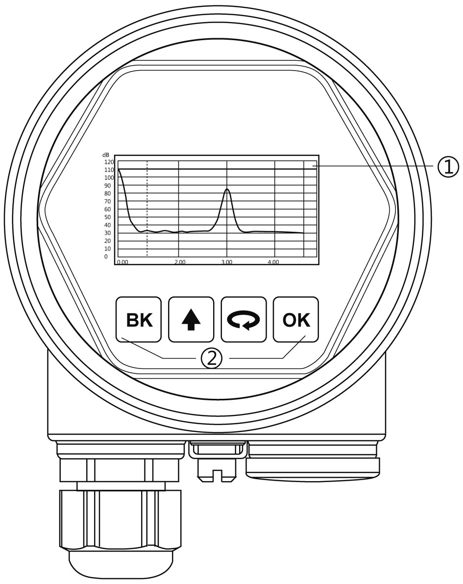
Display / Button:
Debug the meter through the 4 buttons on the display screen. The debugging menu has four languages to choose from. The measured value can be read very clearly through the glass window.
Display / Button
① Liquid crystal display(LCD) ② Adjust by button
PC software debugging:
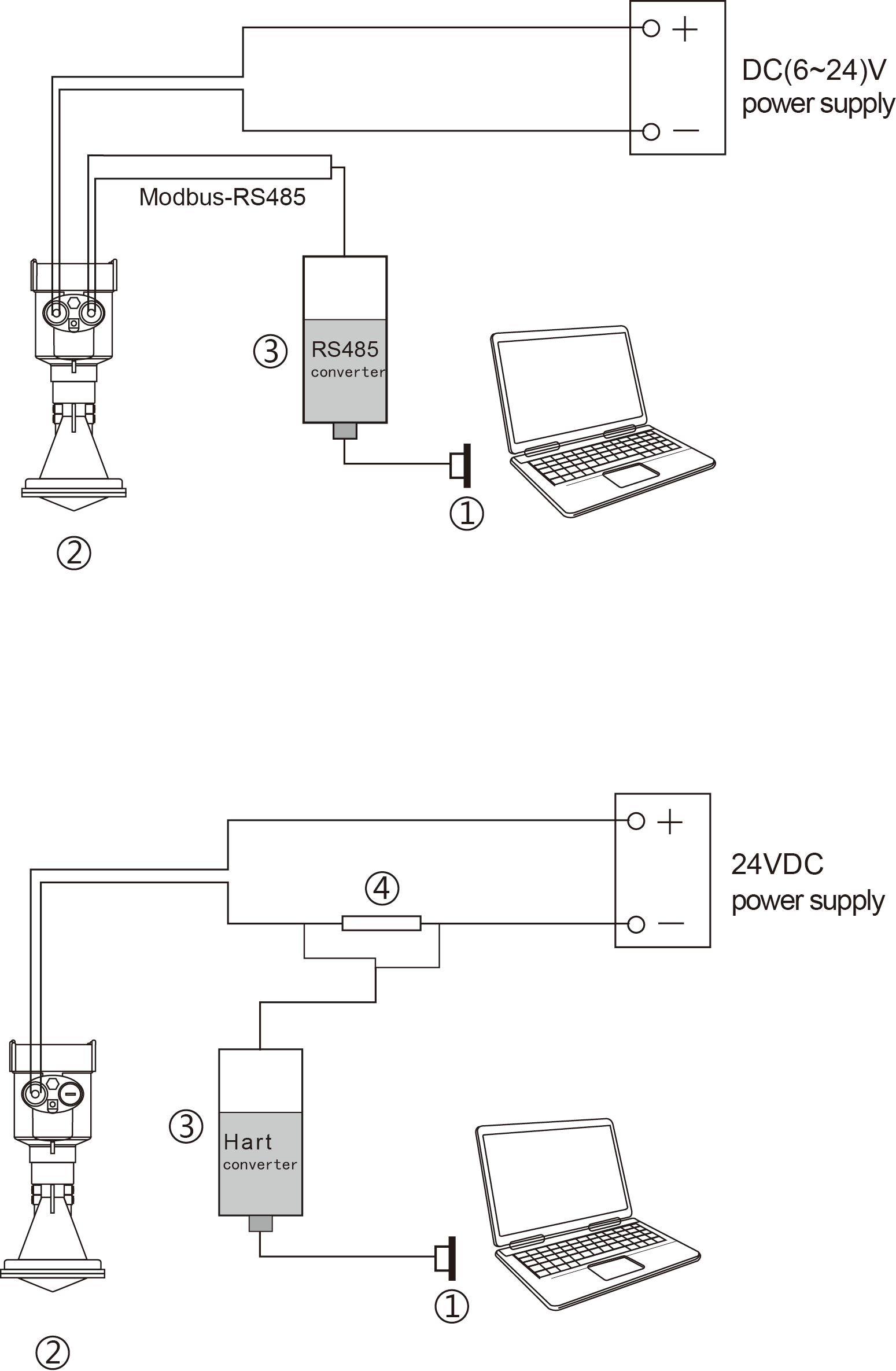
Connected to PC by HART
①USB interface ② Radar level meter ③ HART converter ④ 250Ω resistor
Connected to PC by RS485
①USB interface ②Radar level meter ③RS485 converter
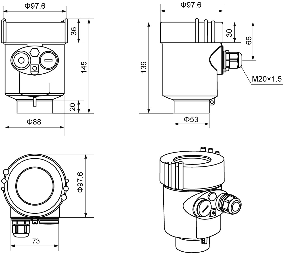
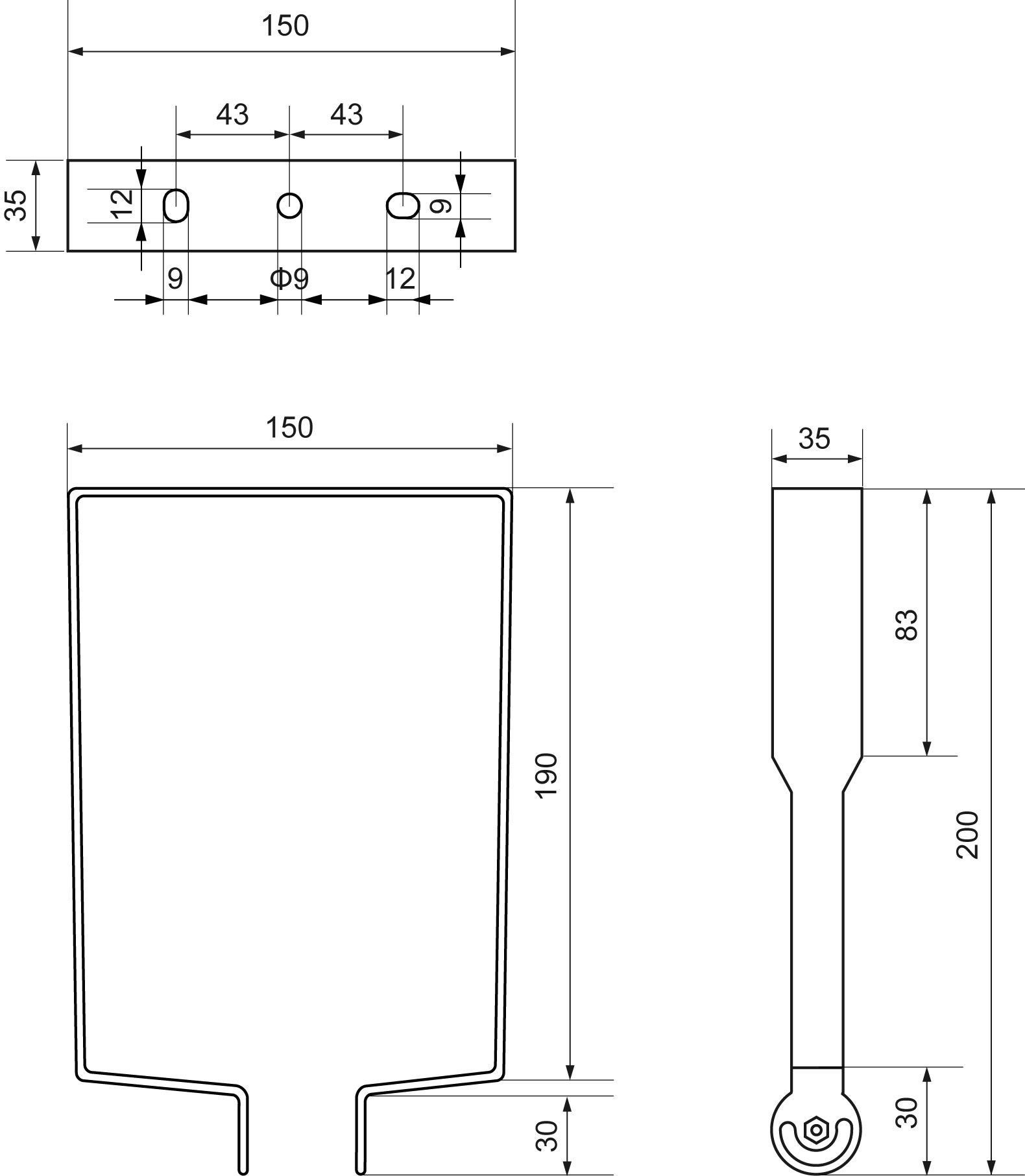
6. Structure Size (Unit: mm)
The outer shell
Ø Cast aluminum shell
Plastic shell
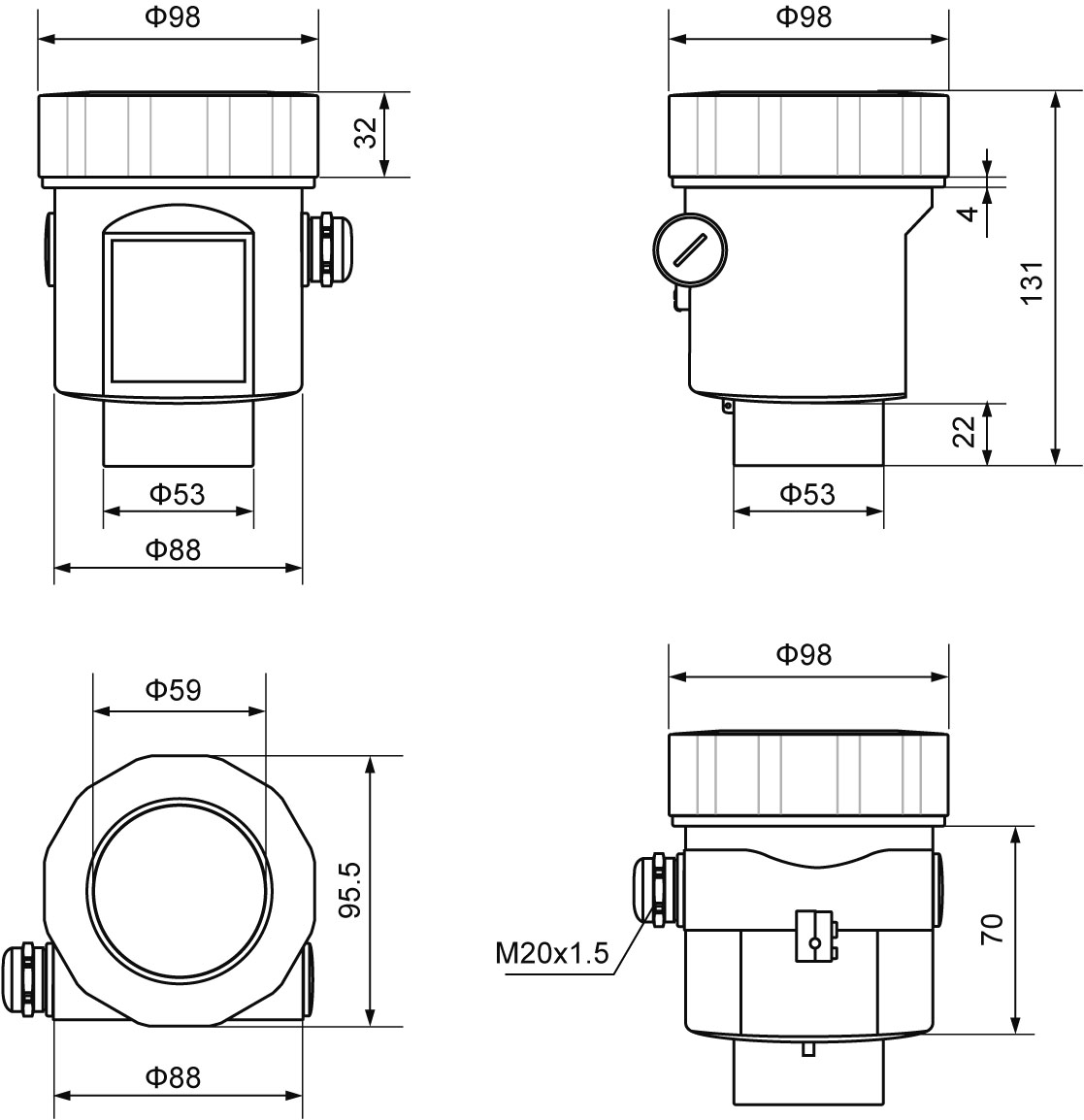
Product size:

With split display, split size:
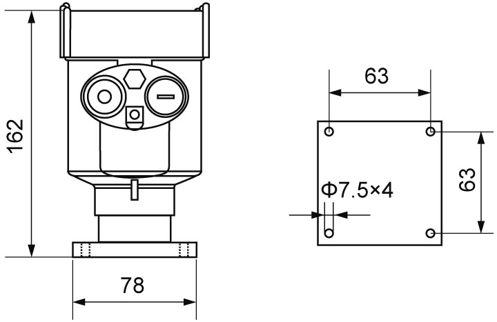
Gantry frame size:
7. Technical Parameters
General data | |
| The outer shell material | Cast aluminum, stainless steel, plastic |
The seal between the shell and cover | Silicone rubber |
Casing window | Polycarbonate |
The ground terminal | Stainless steel |
The power supply | |
Two wire system | DC 24V / 4~20mA / Power dissipation 0.75W |
Four wire system | (6~24) V DC / Modbus-RS485 / Power dissipation 90mW |
Allowable ripple | - <100Hz Uss<lV - (100~100K) Hz Uss<l0mV |
The cable parameters | |
Cable entrance / plug | 1 M20xl.5 cable entrance |
| Terminal | Conductor cross section 1.0mm² |
Output parameters | |
The output signal | (4 ~ 20) mA / Modbus-RS485 |
Communication protocol | Modbus / HART |
Resolution | 1.6μA |
Fault signal | Constant current output; 20. 5mA;22mA;3.9mA |
The integral time | (0 ~ 36) s, adjustable |
| Characteristic Parameters | |
| Blind area | the ends of the antenna |
Maximum distance measuremen | 30 meters |
Microwave frequency | 26GHz |
The measurement interval | about 1 second (depending on the parameter settings) |
Adjust the time | about 1 second (depending on the parameter settings) |
Display resolution | 1mm |
Working storage and transportation temperature | (-40~80) ℃ |
Process temperature (the temperature of the antenna part) | (-20~100)℃ |
Pressure | Normal atmospheric pressure |
Seismic | Vibration frequency (10~150) Hz, maximum vibration acceleration l0m/s² |
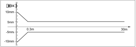
8. Meter Linearity
908S
The launch angle depends on the antenna size
-Φ76mm 12°
Precision See chart
9. Product Model Selection
908S
License |
P standard (non-explosion-proof) |
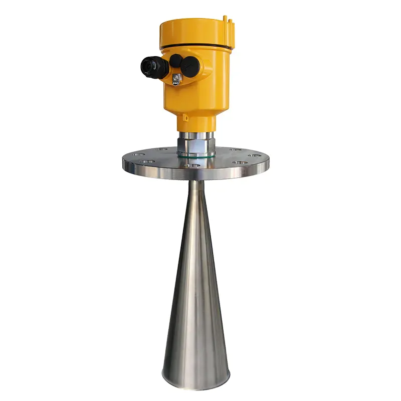
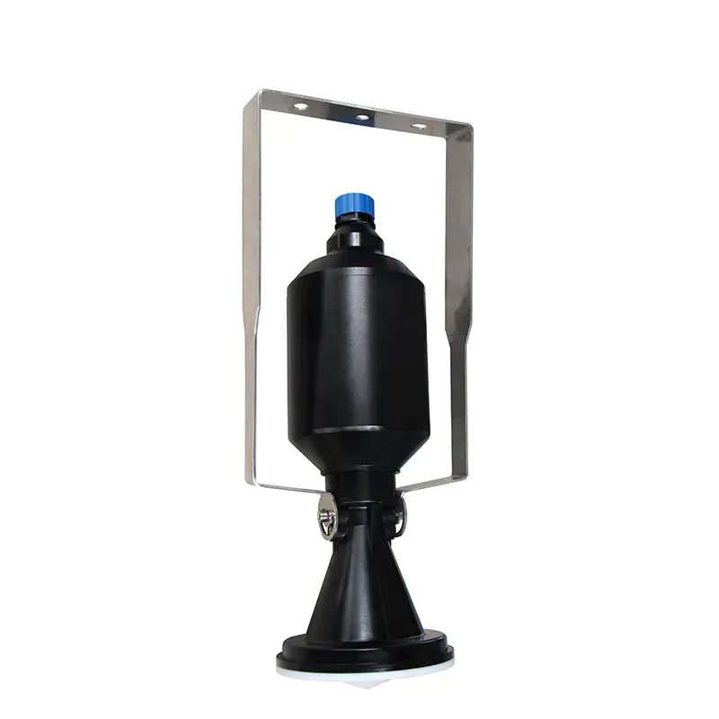
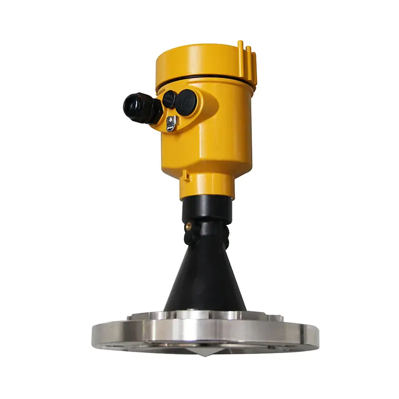
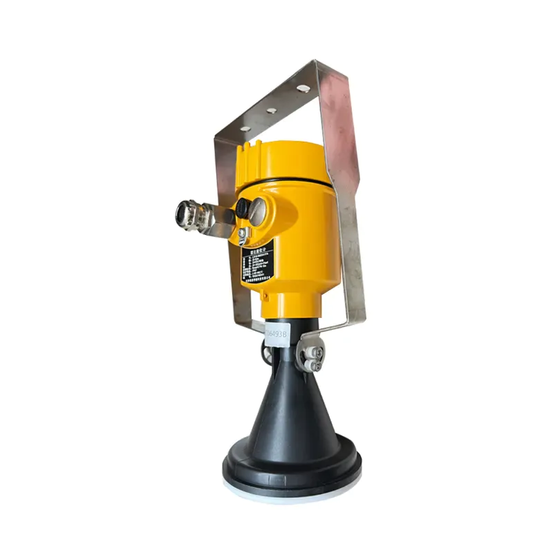
Process connection / material |
N gantry frame M PP flange installation Y special customization |
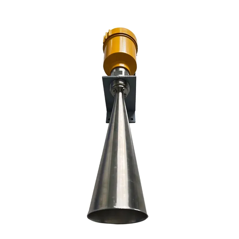
Antenna type/material |
A Horn antenna Φ76mm/PP Y special customization |
Seal / process temperature |
V Ordinary seal/(-40~80) ℃ |
Electronic unit |
V Modbus-RS485 / 6~24V DC four-wire system W (4~20) mA / 24V DC two-wire system |
Enclosure rating |
L aluminum/IP67 G plastic /IP65 |
Cable entry |
M M20 × l. 5 N ½″ NPT |
The scene shows/programming |
A With X With |
We are here to help you! If you close the chatbox, you will automatically receive a response from us via email. Please be sure to leave your contact details so that we can better assist
![kaidi KD-908S 26G Radar Level Meter [Anti-corrosion Type]](https://img80003270.weyesimg.com/uploads/kaidi86.com/images/16945010227981.png?imageView2/2/w/1920/q/80/format/webp)