Español
  pусский
  العربية
  Português
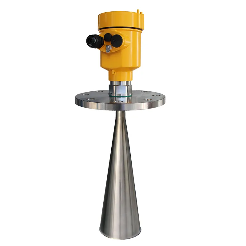
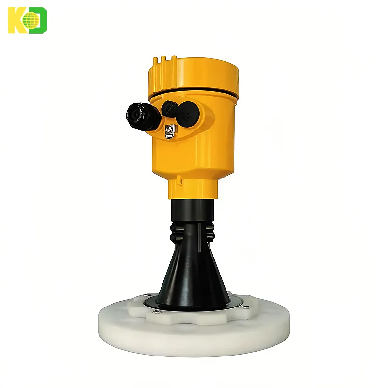
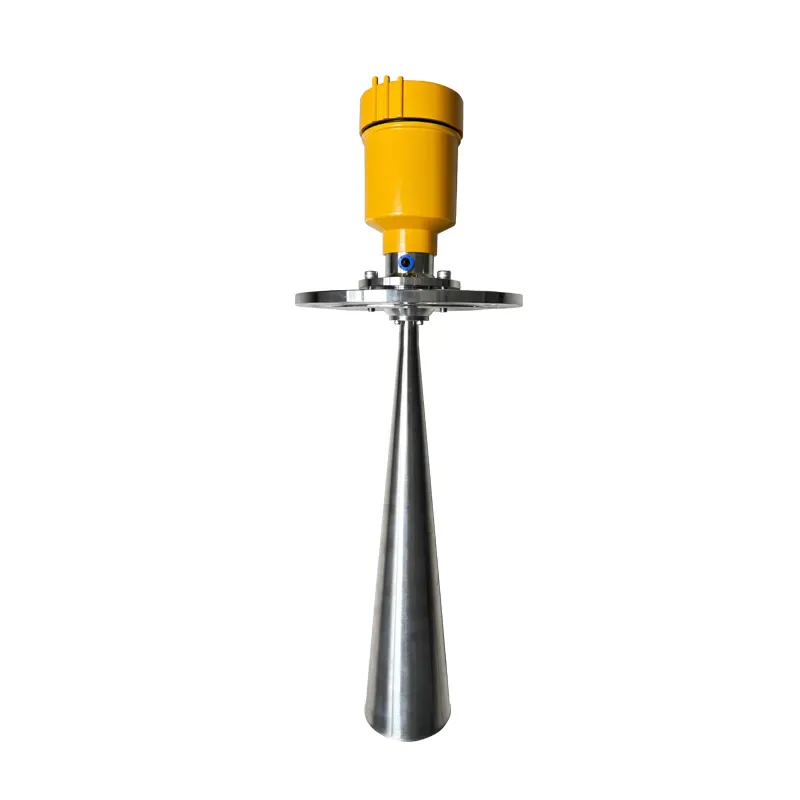
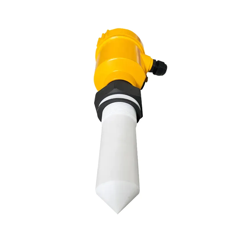
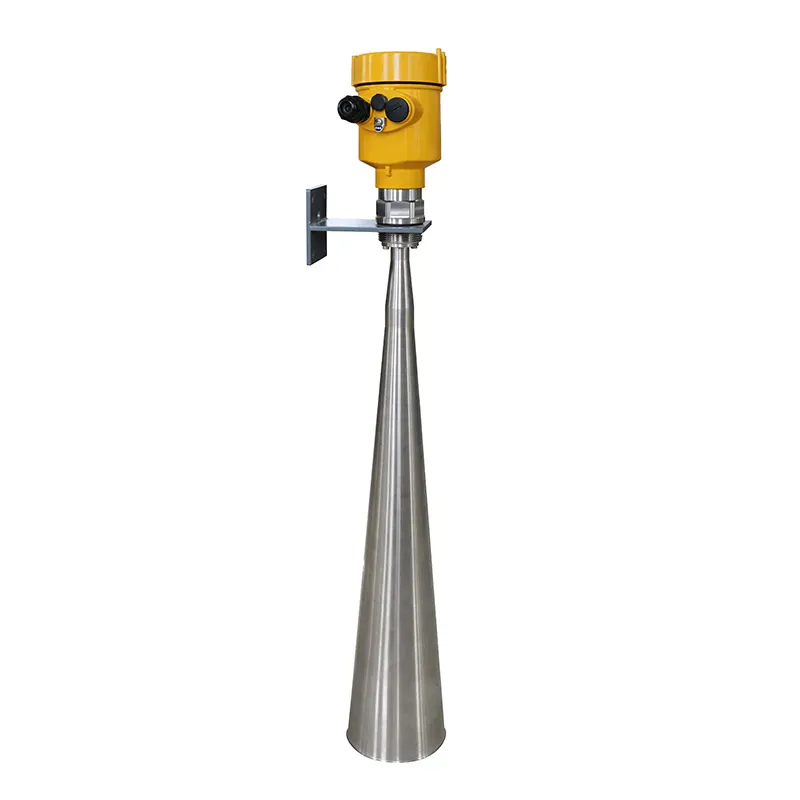
![kaidi KD-908S 26G Radar Level Meter [Anti-corrosion Type]](https://img80003270.weyesimg.com/uploads/kaidi86.com/images/16945046182991.png?imageView2/2/w/1920/q/80/format/webp)
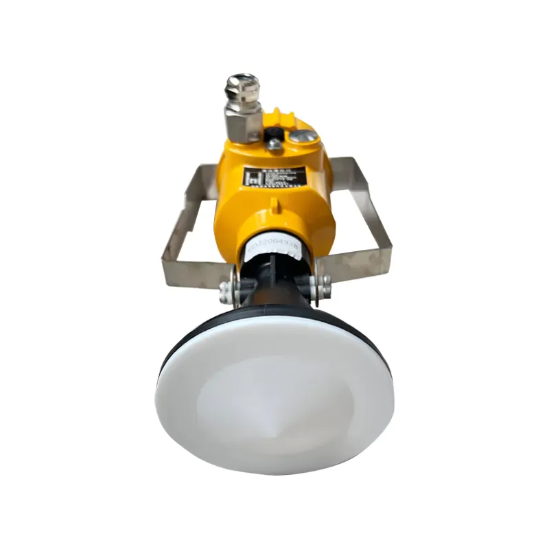
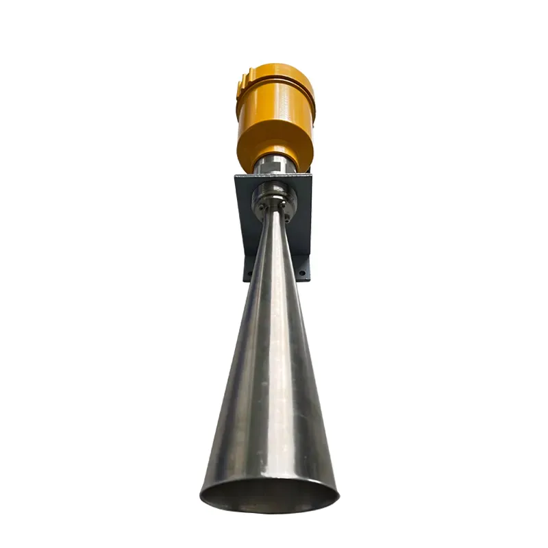
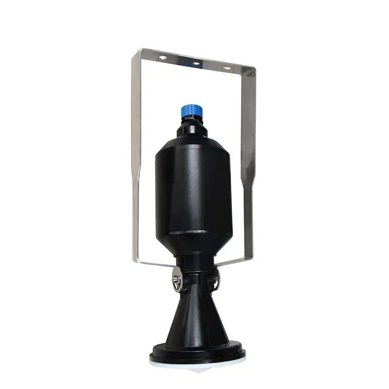
kaidi KD-908S 26G Radar Level Meter [Anti-corrosion Type]

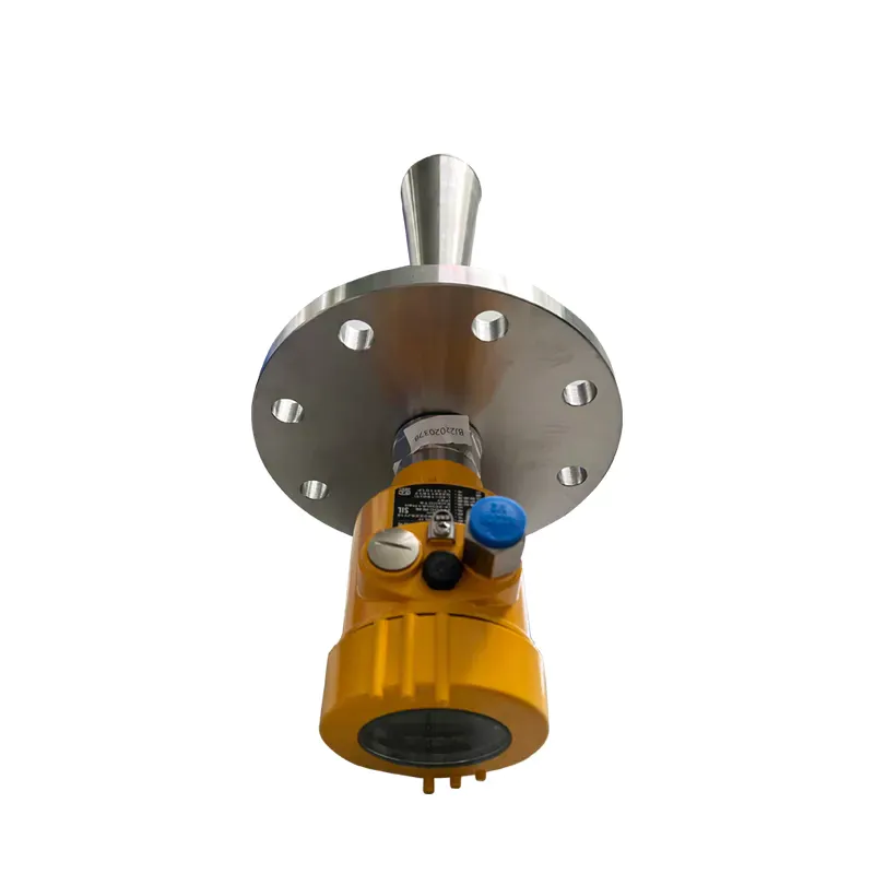
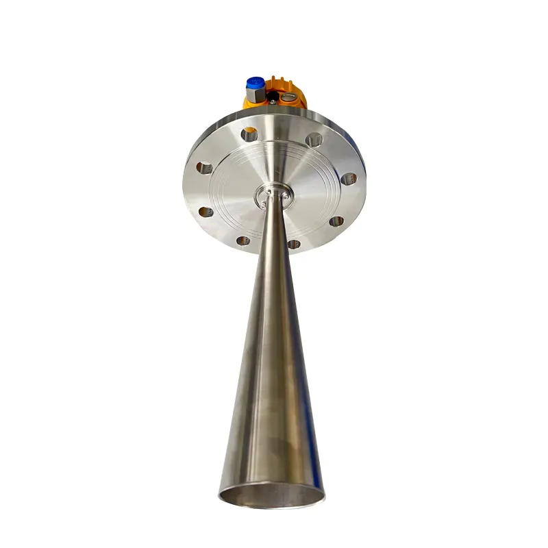
1. Product Overview
High Frequency Radar Level Meter 902 adopted 26G high frequency radar sensor, the maximum measurement range can reach up to 30 meters. Antenna is optimized further processing, the new fast microprocessors have higher speed and efficiency can be done signal analysis, the instrumentation can be used for reactor, solid silo and very complex measurement environment.
Principle
Radar level transmitter antenna microwave pulse is narrow, the downward transmission antenna. Microwave exposure to the medium surface is reflected back again by the antenna system receives, sends the signal to the electronic circuit automatically converted into level signals (because the microwave propagation speed, electromagnetic wave to reach the target and the reflected back to the receiver this time is almost instantaneous).
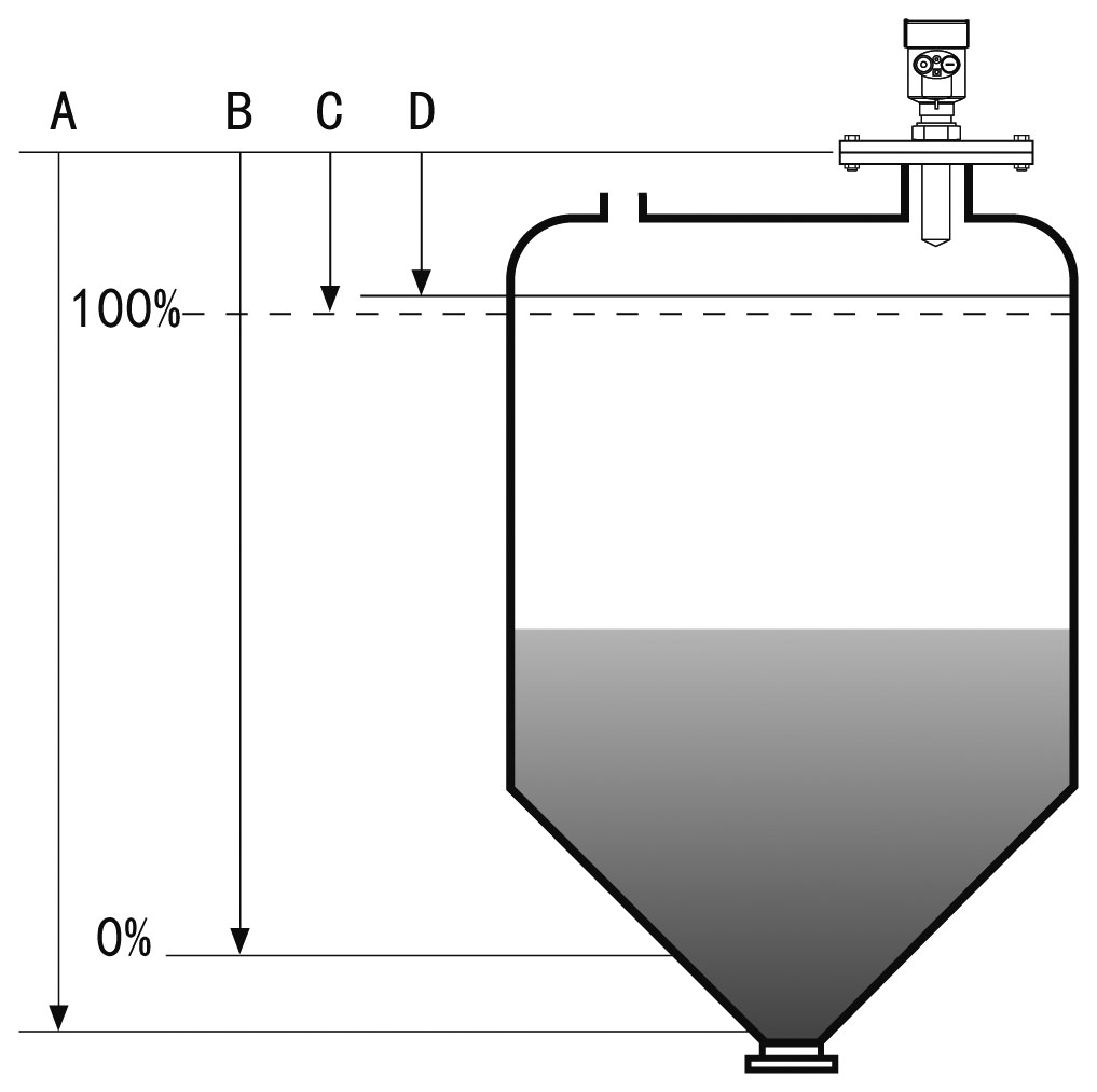
A Range set
B Low adjustment
C High
D Blind area
Datum measurement: Screw thread bottom or the sealing surface of the flange.
Note: Make sure the radar level meter the highest level cannot enter the measuring blind area (Figure D shown below).
The characteristics of 26G radar level meter:
Ø Small antenna size, easy to install; Non-contact radar, no wear, no pollution.
Ø Shorter wavelength, and there is better reflection on the solid surface.
Ø The measurement blind zone is smaller, and good results can be obtained for the measurement of small tanks.
Ø Hardly affected by corrosion and slight foam.
Ø Hardly affected by water vapor, temperature and pressure changes.
Ø Severe dust environment will not affect electromagnetic wave work.
Ø High signal-to-noise ratio, better performance can be obtained even with fluctuations.
Ø The wave speed gathering effect is very good, with various types of antennas, it can meet 90% of the working conditions.
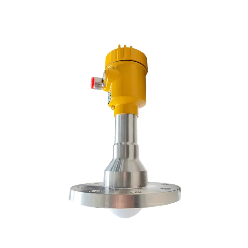
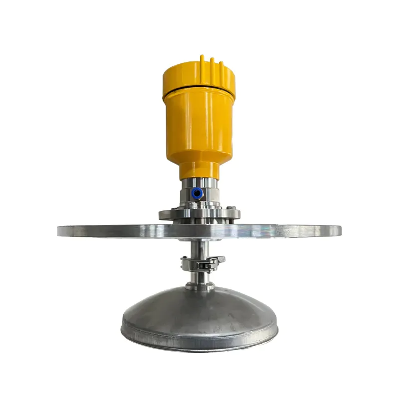
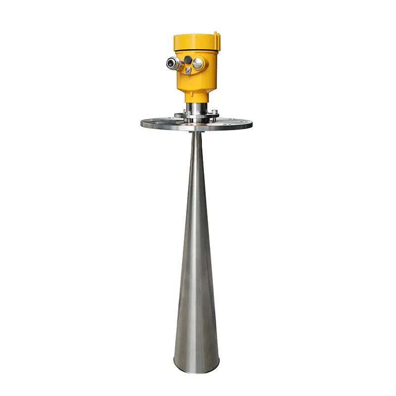
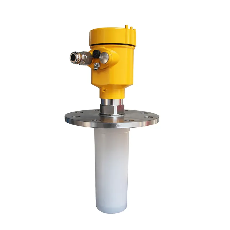
2. Product Introduction
902
3. The Installation Requirements
Installation notes:
There should be no obstacles between the bottom of the antenna and the surface of the measured medium, and the installation in the tank should be avoided as much as possible, such as: human ladders, limit switches, heating equipment, brackets, etc. Also note that the microwave beam must not intersect the material flow.
When installing, pay attention to the maximum liquid level not to enter the blind area of the measurement; the instrument must be kept a certain distance from the tank wall; the installation of the instrument should make the antenna emission direction perpendicular to the surface of the measured medium as much as possible.
Instruments installed in explosion-proof areas must comply with the national installation regulations for explosion-proof hazardous areas. Explosion-proof instruments can be installed in places with explosion-proof requirements, and the instruments must be connected to the ground. The shell of the explosion-proof instrument is made of cast aluminum.
Installation location:
The instrument is installed at 1/4 or 1/6 of the diameter of the tank.
Note: The minimum distance from the tank wall should be 200mm.
① datum ②The container center or axis of symmetry
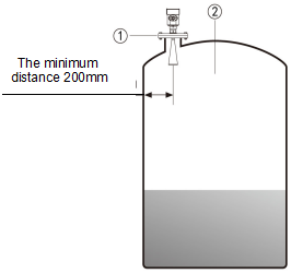
For conical tanks, the top is flat, and the meter needs to be installed in the middle of the tank top. It can be guaranteed to measure to the bottom of the cone.
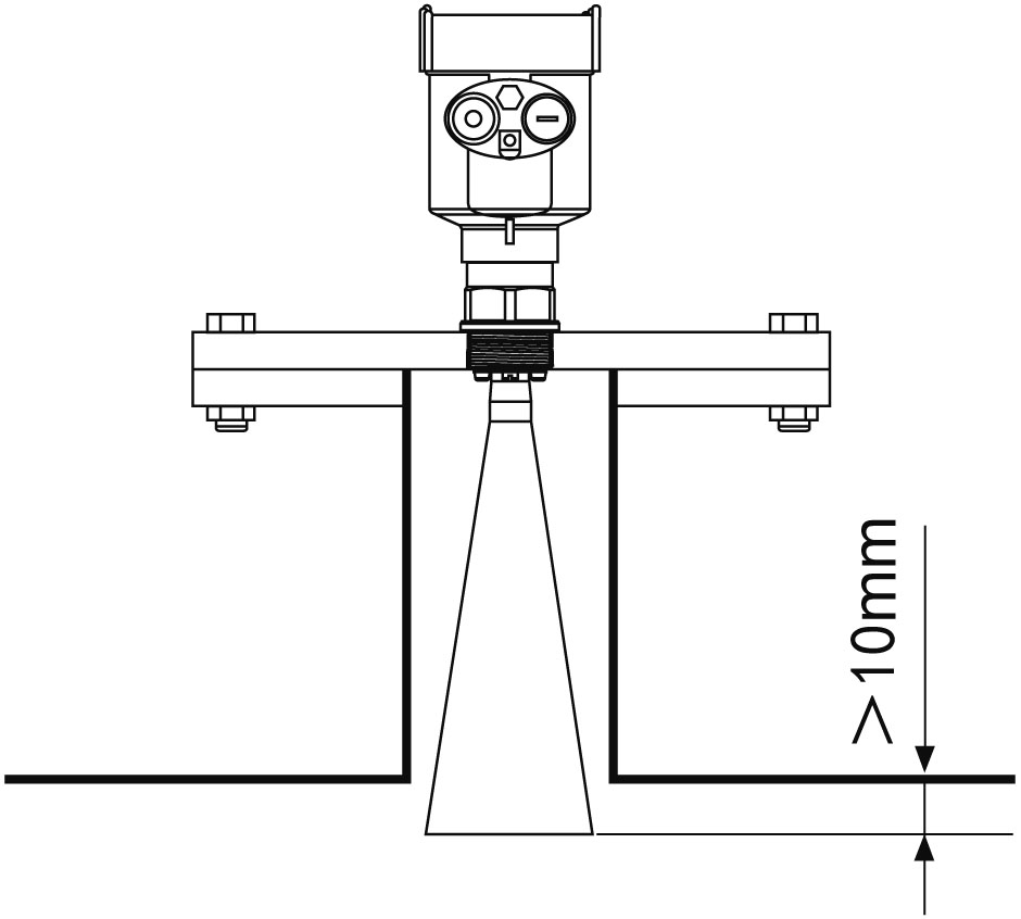
l Container takeover requirements:
Make sure that the antenna extends into the tank at least 10mm away.
Typical installation errors:
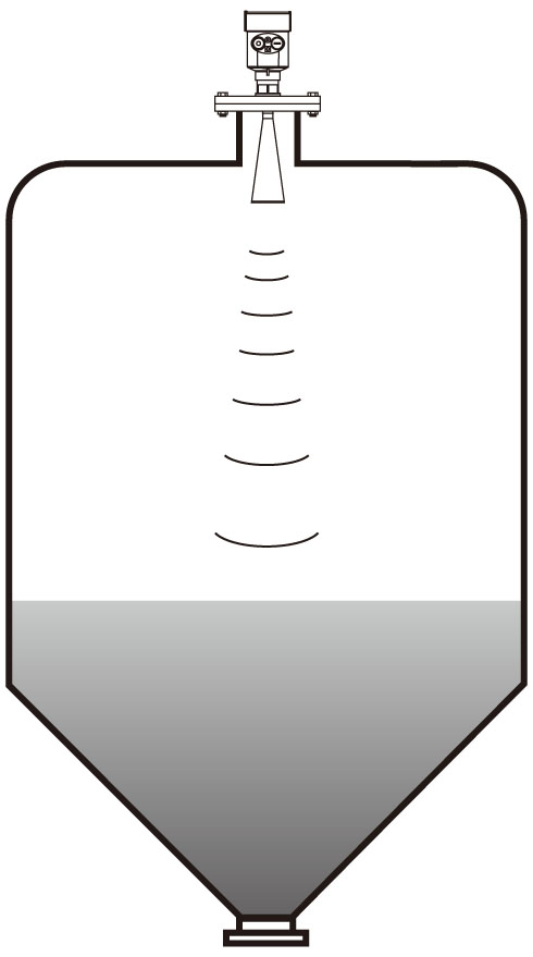
Ø Conical tank
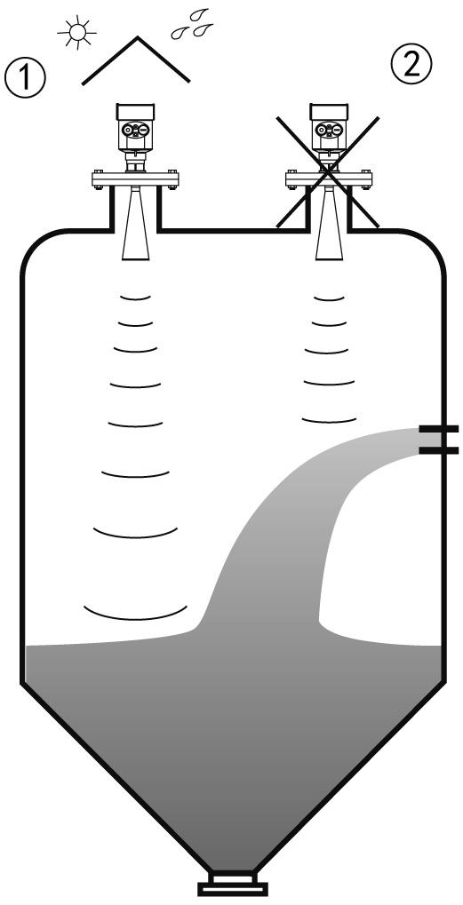
The instrument cannot be installed above the inlet.
Note: Sun-shading and rain-proof measures should be taken during outdoor installation..
①Correct ②Error rainproof measures
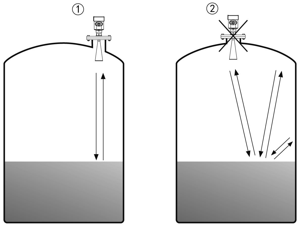
Ø The meter cannot be installed in the middle of the top of an arched or round tank. In addition to producing indirect echoes, it will also be affected by multiple echoes. Multiple echoes may be larger than the signal threshold of true echoes, because multiple echoes can be concentrated through the top, so they cannot be installed in the center.
①Correct ②Error
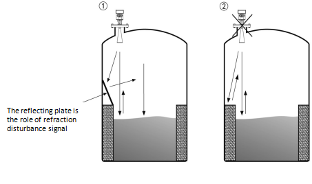
Ø When there are obstacles in the tank that affect the measurement, it is necessary to install a reflector to measure normally.
①Correct ②Error
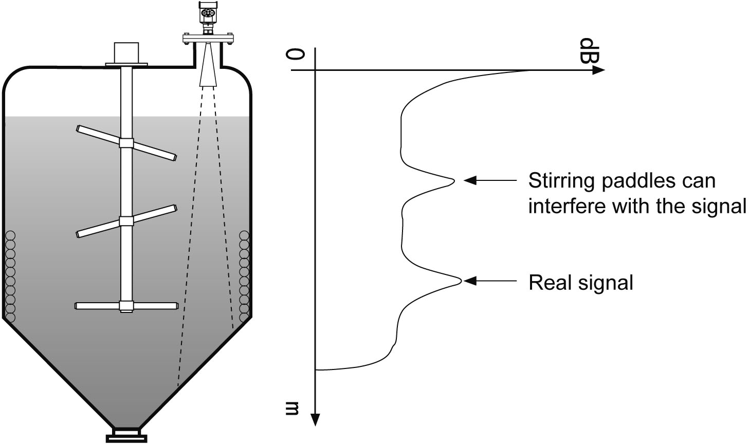
Measurement with stirring:
When there is stirring in the measuring tank, please try to stay away from the stirring paddle. After the instrument is installed, it is necessary to perform "false echo learning" in the stirring state to eliminate the influence of false echoes generated by the stirring blade. If foam or waves are generated during the stirring process, the still-pipe installation method should be used.
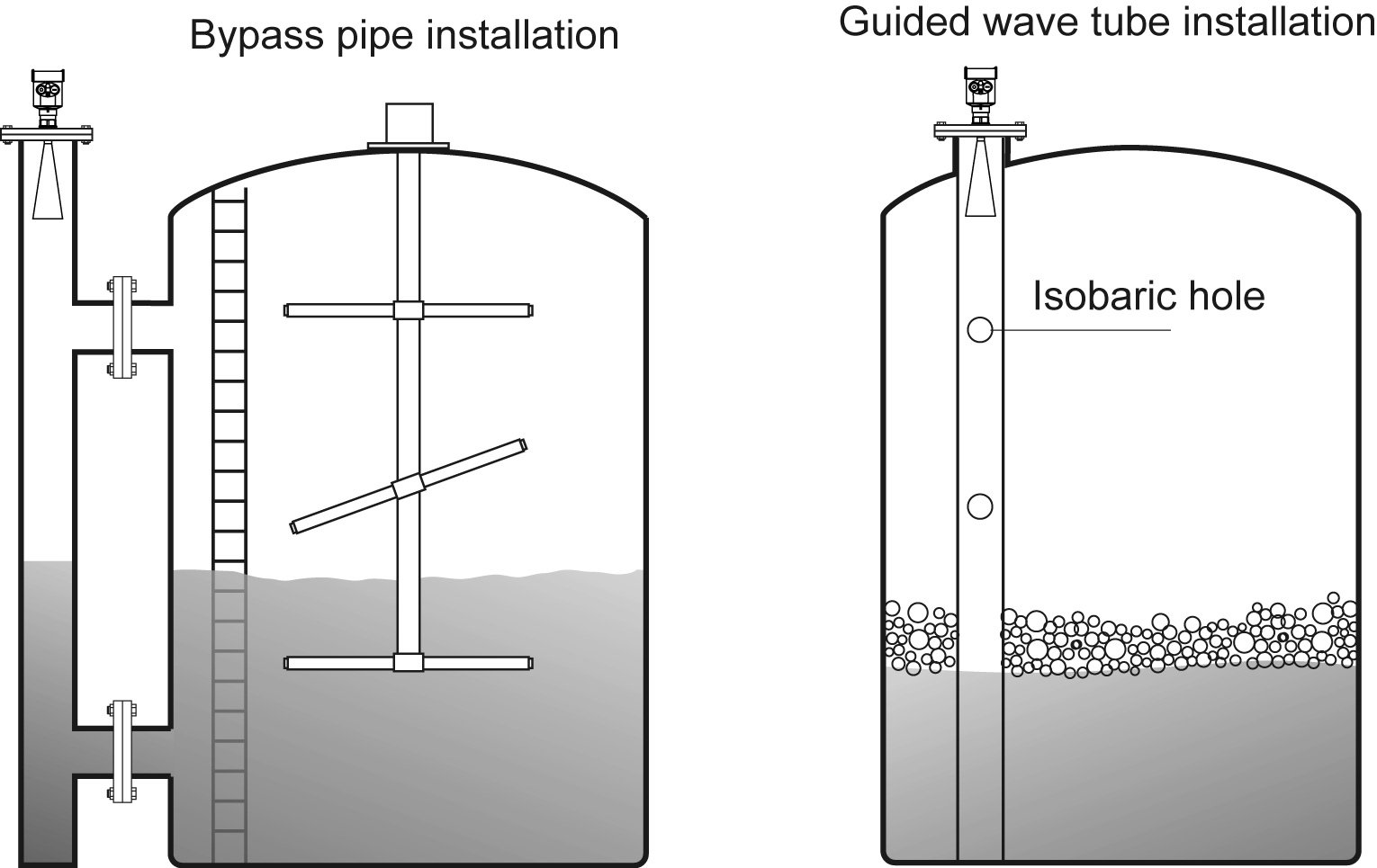
Installation of guided wave tube:
Ø The instrument is equipped with guide wave tube (or bypass tube) for measurement, which can avoid the influence of obstacles and foam in the container on the measurement.
Ø Due to stirring or some process reactions, foam will be formed on the surface of the liquid, and the foam will attenuate the signal, so a stilling wave tube should be installed for measurement.
Ø Install guide wave tube during measurement, the minimum diameter of guide wave tube should be 50mm. When connecting still pipes, avoid large cracks and welds. If necessary, "false echo learning" is required.
Ø When measuring with adhesive medium, the guided wave tube should not be used.
4. The Electrical Connection
The power supply voltage:
(4~20)mA/HART (Two wire system) | The power supply and the output current signal sharing a two core shield cable. The supply voltage range see technical data. For intrinsically safe type must be a safety barrier between the power supply and the instrument. |
| (4~20)mA/HART(Four wire system) | Separate power supply and the current signal, respectively using a two-core shielded cable. The supply voltage range see technical data. |
| RS485 / Modbus | Power supply and Modbus signal line separated respectively using a two-core shielded cable, the power supply voltage range see technical data. |
Cable Connection
General Introduction | Supply cable can use ordinary two-core cable, the cable diameter should be (6~12) mm, to ensure that the cable entry seal. If electromagnetic interference exists, recommended to use shielded cable. |
(4~20) mA /HART(Two-wire) | Supply cable can use ordinary two-core cable. |
(4~20) mA /HART(Four-wire) | Supply cable should be used with a dedicated ground cable |
Modbus-RS485(Four-wire) | Shielded cable should be used for the power supply cable. |
| Shielding and wiring | Both ends of the shielded cable should be grounded. Inside the sensor, the shield must be connected to the internal ground terminal. The external ground terminal on the enclosure must be connected to the ground. If there is ground current, the shielded cable must be grounded through a ceramic capacitor (for example: 1nF/1500V) far away from the shielding end of the instrument side to block direct and bypass high-frequency interference signals. |
Connection mode
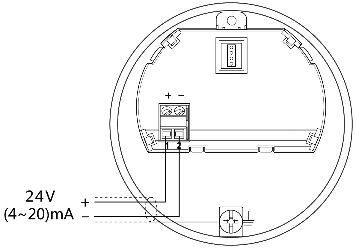
Ø 24V two wire wiring diagram as follows:
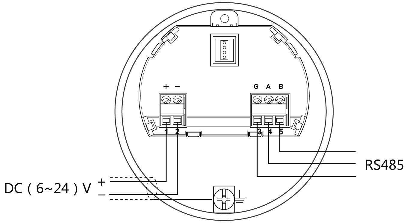
Ø 6~24V Modbus-RS485 wiring diagram as follows:
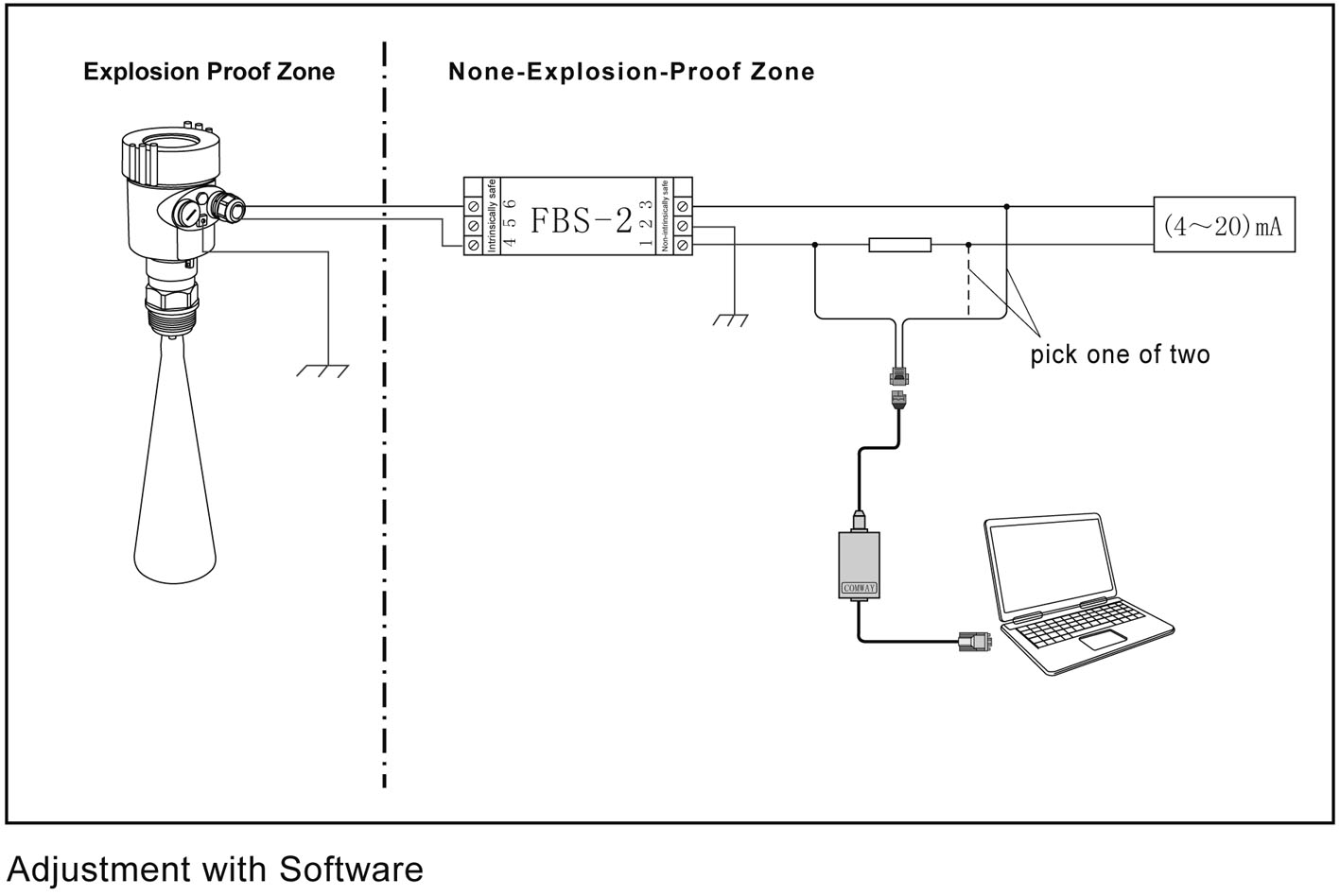
Explosion Proof Connection
The explosion-proof form of this product is intrinsically safe.The intrinsic safety version sensors (Exia Ⅱc T6) use Alu-die casting housing and filling Silicone rubber sealants internal structure aimed to prevent sparks resulted from circuit failure from leaking out. It is applicable for the continuous level measurement of flammable medium under Exia Ⅱc T6.
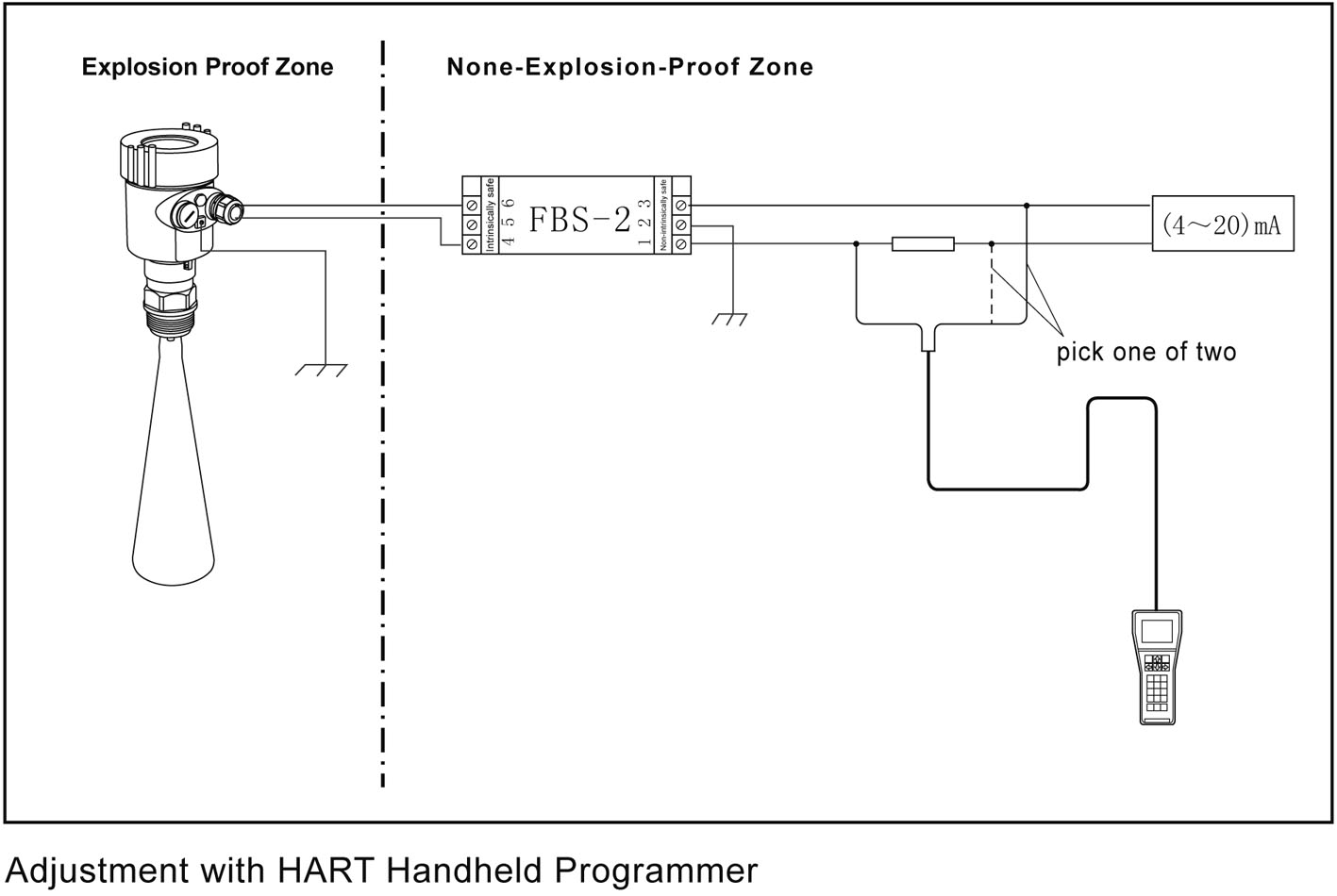
A safety barrier FBS-2 must be used together with the intrinsic safety instrument. It is an associated device to this product for the power supply of this product. The main specification is intrinsic safety: ExiaⅡc, voltage of power supply: 24V DC±5%, short-circuit current: 135mA, operating current: 4...20mA.
All cables must be shielded. The max length is 500m for the cable from the barrier to the sensor. Stray capacitor≤0.1μF/Km, stray inductance 1mH/Km. Instrument must be connected to the ground potential. Any unapproved associated device is not allowed to be used.
Safety instructions:
Ø Please observe the local electrical code requirements!
Ø Please comply with local requirements for personnel health and safety regulations.
All electrical components of instrument operation must be completed by the formal training of professionals.
Ø Please check the instrument nameplate to provide product specifications meet your requirements. Please make sure that the power supply voltage and instrument nameplate on the requirements.
Protection grade:
This meter fully meets the requirements of protection class IP66/IP67, please ensure the waterproof characteristics of the cable seal. As shown below:
How to install to meet the requirements of IP67:
Please make sure that the sealing head is not damaged.
Please make sure that the cable is not damaged.
Please make sure that the cable for use with electrical connection specification.
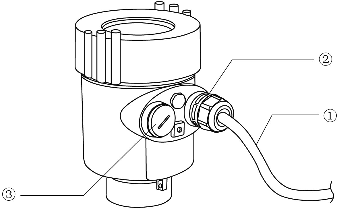
Cable into the electrical interface before its curved downward, ensure that the water will not flow into the shell, see the①
Tighten the cable seal head, see the②
Please electrical interface will not use blind plug tight, see the③
5. Instrument Commissioning
Three kinds of debugging method:
1) Display / Button (With split display, you need to debug on the split)
2) Debug through computer software
3) HART Handheld programmer
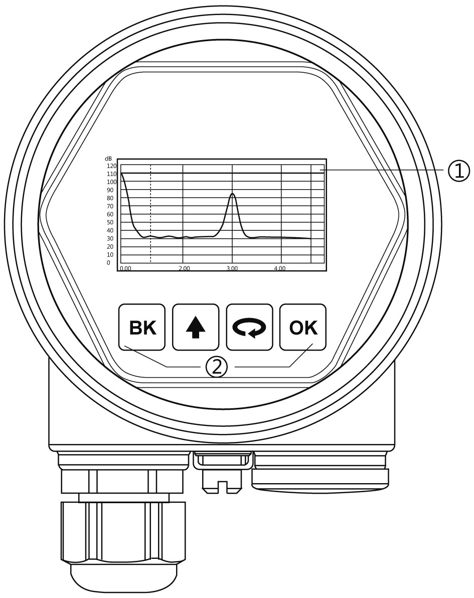
Display / Button:
Debug the meter through the 4 buttons on the display screen. The debugging menu has four languages to choose from. The measured value can be read very clearly through the glass window.
Display / Button
① Liquid crystal display(LCD) ② Adjust by button
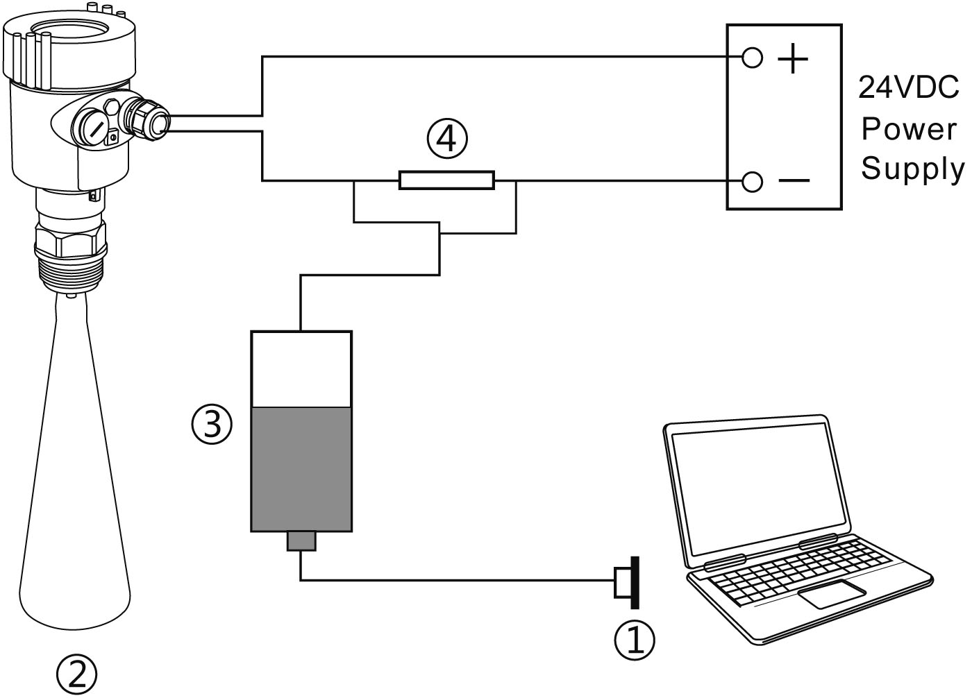
PC debugging:
Connected to PC by HART
① USB interface ② Radar level meter ③ HART converter ④ 250Ω resistor
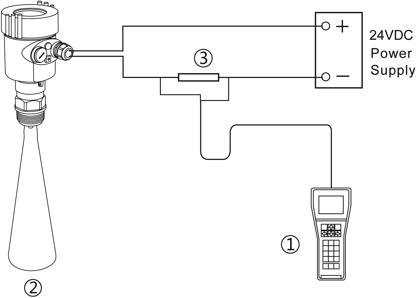
HART handheld programmer:
① HART handheld programmer ② Radar level meter ③ 250 Ω Resistor
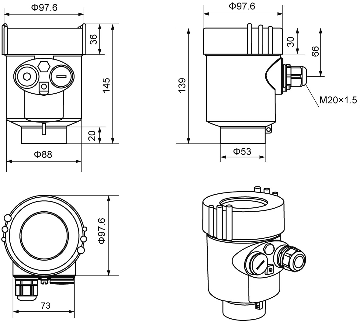
6. Structure Size (Unit: mm)
The outer shell
Ø Cast aluminum shell
Plastic shell
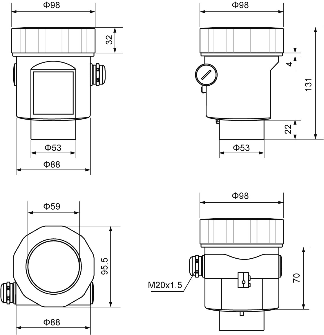
Appearance size:
902
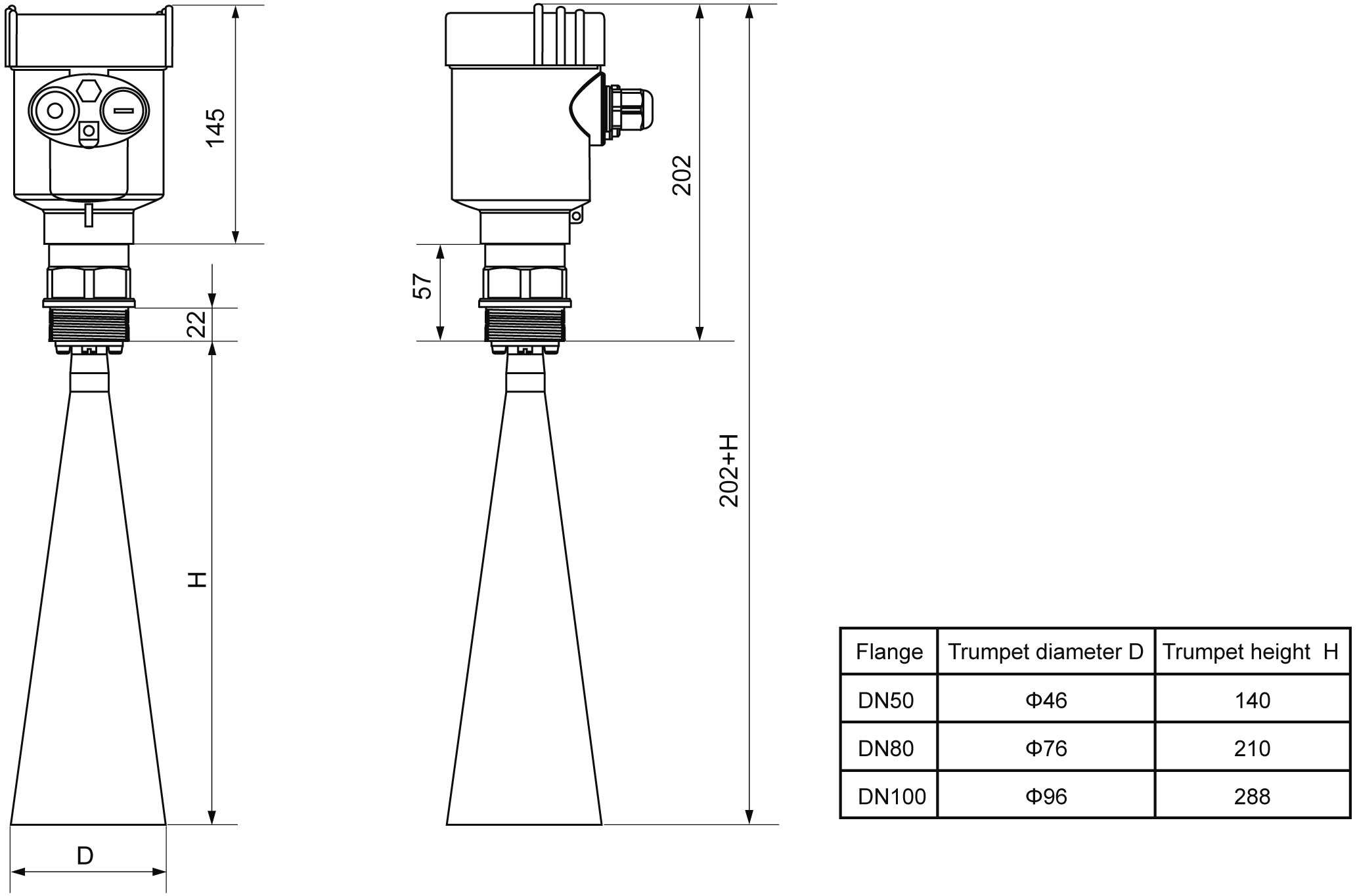
Flange type:
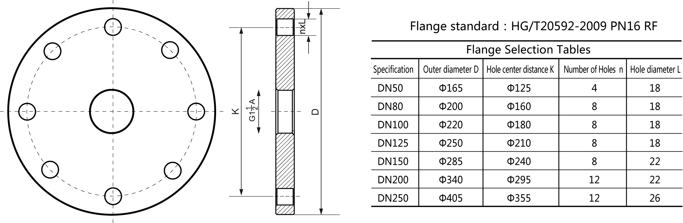
7. Technical Parameters
General data | |
Process Connection | Thread G1½″A / Thread 1½″NPT / Flange |
Antenna Material | Stainless steel |
The outer shell material | Cast aluminum, stainless steel, plastic |
The seal between the shell and cover | Silicone rubber |
Casing window | Polycarbonate |
The ground terminal | Stainless steel |
The power supply voltage | |
Two wire system | 24V DC |
Four wire system | 6~24V DC ( Modbus-RS485 ) 198 ~242 VAC (Flameproof type /Double chamber) 110 VAC (Flameproof type /Double chamber) |
Power dissipation | Max. 22.5mA / 1W |
Allowable ripple | - <100Hz Uss<lV - (100~100K) Hz Uss<l0mV |
The cable parameters | |
Cable entrance / plug | 1 M20xl.5 cable entrance 1 Blind plug (M20×l.5) |
| Terminal | The maximum usable wire is 2.5mm² |
Output parameters | |
The output signal | (4 ~ 20) mA / Modbus-RS485 |
Resolution | 1.6μA |
Fault signal | Constant current output; 20. 5mA;22mA;3.9mA |
The integral time | (0 ~ 36) s, adjustable |
Two-wire load resistance | See below |
Four-wire load resistance | Max 500Ω |
The integral time | (0 ~ 36) s, adjustable |
| Characteristic Parameters | |
| Blind area | the ends of the antenna |
Maximum distance measuremen | 30 meters |
Microwave frequency | 26GHz |
Communication interface | HART communication protocol Modbus-RS485 communication protoco |
The measurement interval | about 1 second (depending on the parameter settings) |
Adjust the time | about 1 second (depending on the parameter settings) |
Display resolution | 1 mm |
Working storage and transportation temperature | (-40~80) ℃ |
Process temperature (the temperature of the antenna part) | (-40~130)℃ Standard type/ (-40~230)℃ High temperature type |
Relative humidit | ˂ 95% |
Pressure | Max.4MPa |
Shock resistance | Vibration frequency (10~150) Hz, maximum vibration acceleration l0m/s² |
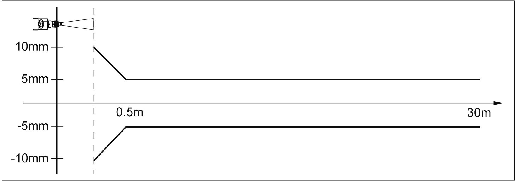
8. Meter Linearity
902
The launch angle depends on the antenna size
-¢46mm 18°
-¢76mm 12°
-¢96mm 8°
-¢121mm 6°
Accuracy See below(±5mm)
9. Product Model Selection
902
License | |||||||||||||||
P Standard (Non-explosion-proof) I Intrinsically safe (Exia ⅡC T6 Ga) D Flameproof (Exd ⅡC T6 Gb) | |||||||||||||||
Process Connection / Material | |||||||||||||||
G Thread G1½″A / Stainless Steel 304 N Thread 1½″ NPT / Stainless Steel 304 Y Special Custom | |||||||||||||||
| |||||||||||||||
Antenna Type / Material | |||||||||||||||
A Horn Antenna Φ46mm / Stainless Steel 316L B Horn Antenna Φ76mm / Stainless Steel 316L C Horn Antenna Φ96mm / Stainless Steel 316L Y Special Custom | |||||||||||||||
Seal Up / Process Temperature | |||||||||||||||
V Viton / (-40~130) ℃ K Kalrez / (-40~230) ℃ | |||||||||||||||
The Electronic Unit | |||||||||||||||
3 (4~20) mA / 24V DC / HART 2-wire system 4 (4~20) mA / 220V AC / HART 4-wire system 5 Modbus-RS485 / 6~24V / 4-wire system | |||||||||||||||
Outer Covering / Protection Grade | |||||||||||||||
L Aluminum / Single chamber / IP67 H Aluminum / Double chamber / IP67 G Plastic / Single chamber / IP65 K Stainless steel / Single chamber / IP67 | |||||||||||||||
Cable Line | |||||||||||||||
M M 20×1.5 N ½″ NPT | |||||||||||||||
Field Display /The Programmer | |||||||||||||||
A With X Without | |||||||||||||||
We are here to help you! If you close the chatbox, you will automatically receive a response from us via email. Please be sure to leave your contact details so that we can better assist
![kaidi KD-908S 26G Radar Level Meter [Anti-corrosion Type]](https://img80003270.weyesimg.com/uploads/kaidi86.com/images/16945010227981.png?imageView2/2/w/1920/q/80/format/webp)