Abstract: Analysis of electromagnetic flow sensor online periodic inspection information is provided by excellent flowmeter and flowmeter production and quotation manufacturers. Chengfeng Instrument's intelligent
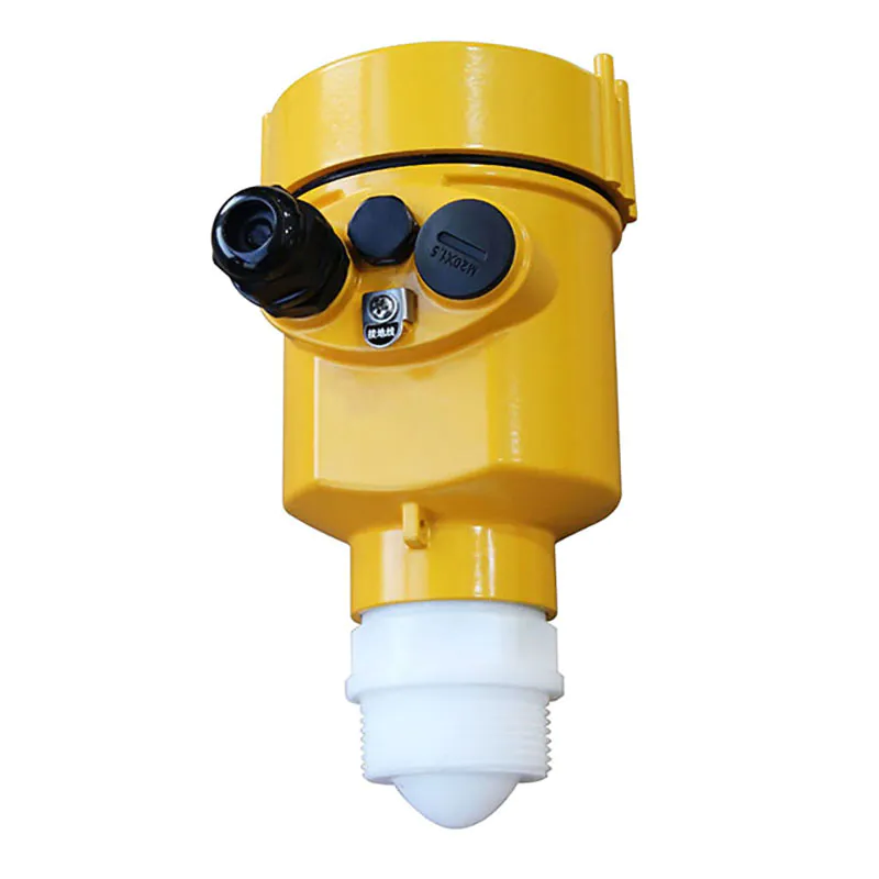
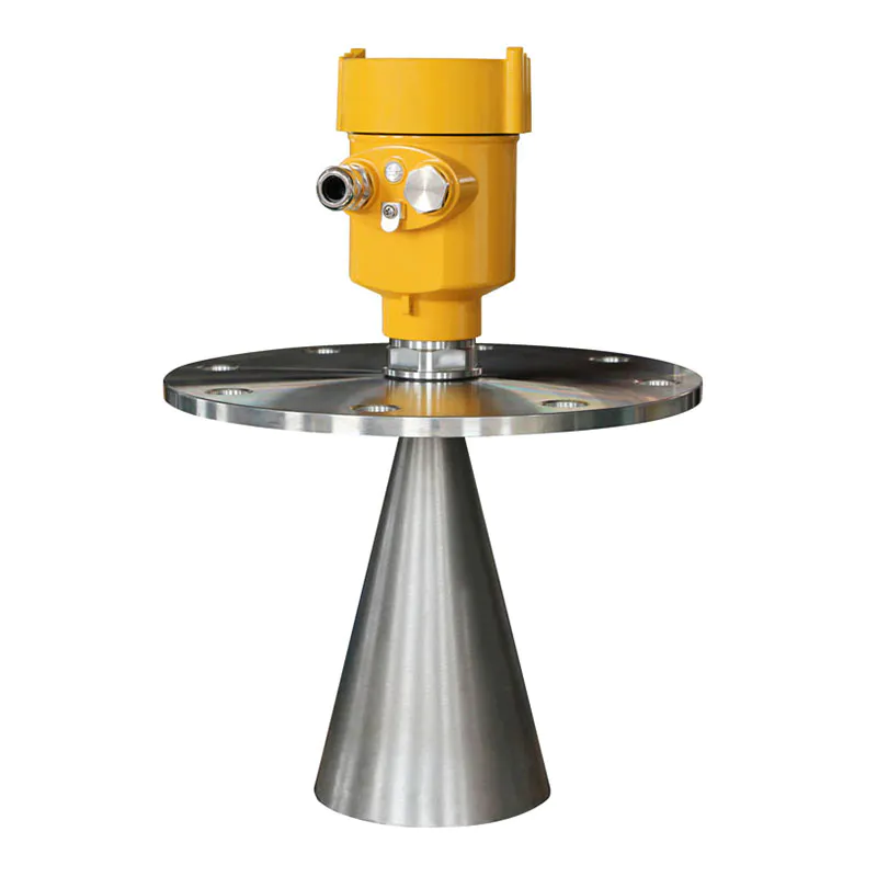
electromagnetic flowmeter is developed based on a standardized manufacturing system. Its advanced design concept ensures the high precision and high reliability of the product. Compared with the old electromagnetic flowmeter, it has high measurement accuracy and reliability. Strong and stable. More flowmeter manufacturers choose models and price quotations. You are welcome to inquire. The following is the details of the article analyzing the online periodic inspection of electromagnetic flow sensors. The intelligent electromagnetic flowmeter is developed based on the standardized manufacturing system. Its advanced design concept ensures the high precision and high reliability of the product. Compared with the old electromagnetic flowmeter, it has high measurement accuracy, strong reliability and stability. It has the advantages of good performance, complete functions and long service life. Measuring instruments must operate under controlled conditions, and therefore must be regularly calibrated. The medium and small diameter
flow meters in the process industry are generally equipped with bypass pipes and corresponding stop valves, and once the meters are commissioned and put into operation, it is generally not allowed to stop water delivery, so it is unlikely to remove the flow sensor and send it to the laboratory offline. Verified on flow standard device. In order to make the measurement of the electromagnetic flowmeter correct and reliable within a period of time without affecting the water delivery of the pipe network, the water supply industry often adopts the method of online inspection and verification instead of regular offline periodic verification. 1. Check the electrode insulation resistance and lining condition. To check the electrode insulation resistance, lining integrity or adhesion layer condition, for small bore meters only remove from the pipeline for inspection. For large-diameter instruments, the measuring medium should be emptied and observed from the manhole into the pipeline. Dry the electrode and the inner surface of the liner without leaving any liquid stains. Use a 500VDC megger to measure the insulation resistance of the two electrodes to the ground respectively. If the lining adhesion layer must be removed, determine the future cleaning interval according to the thickness of the laminate. A large part of the decrease in electrode insulation is caused by the external moisture or water immersion of the sensor, and sometimes it can be recovered by removing the moisture with a hot air blower. If the insulation is indeed damaged, such as electrode leakage, you can only replace the sensor and return it to the manufacturer for repair. 2. Check the insulation resistance of the excitation coil. After the excitation coil and its terminals are damp, the insulation of the excitation circuit to the ground will decrease, which will introduce common mode interference signals, make the zero point of the converter drift, and affect the measurement accuracy. In practice, due to negligence, the junction box is not well sealed, such as installing a sealing gasket at the lead-in end of the cable, introducing moisture, and reducing the insulation of the terminal is a frequent failure case. Dry the terminal with a hot hair dryer, usually the insulation can be improved or restored to the factory insulation level, and the fault can be eliminated. 3. Measure the copper resistance of the excitation coil. Measure the coil resistance with a high-precision digital multimeter or a Wheatstone bridge, and correct the temperature coefficient if necessary. Compare the measured value with the instrument file value to confirm that the coil is well connected and there is no short circuit between turns. In fact, the probability of short circuit between turns of the coil is very low. This check, together with the converter excitation current check, indirectly evaluates whether the magnetic field strength of the flow sensor has changed. 4. Check the insulation of the signal circuit and the insulation between the excitation circuit/signal. The purpose of this inspection is also to evaluate the interference introduced by the insulation degradation. When checking the signal circuit, the signal wire should be temporarily disconnected from the electrode. Insulation degradation can occur for many reasons, with unsealed junction boxes entering moisture being a common cause. 5. Check the electrode contact resistance. Measuring the contact resistance between the electrode and the liquid can indirectly evaluate the general condition of the electrode and the backing layer, such as whether the electrode surface and the backing layer are attached to the deposition layer, and whether the deposition layer is conductive or insulating. The electrode contact resistance of the flow sensor should be measured immediately after the newly installed instrument is debugged and recorded. After each measurement is performed during maintenance, analyzing and comparing these data will help to identify the cause of the instrument failure. The contact resistance between the electrode and the measured medium depends on the size of the contact surface (ie the size of the electrode end face) and the conductivity of the measured medium. When the measured electrode contact resistance value is compared with the original measured value, if it is inconsistent, there may be the following different trends: (1) The resistance value increases. Indicates that the electrode surface is covered with an insulating layer. (2) The resistance value is reduced. It indicates that there is a conductive deposition layer on the surface of the electrode, or the insulation performance of the electrode is reduced. Experience has shown that the contact resistance values of the two electrodes are close. The difference between the two resistance values should be less than 10% to 20%. Otherwise, it means that the insulation of the adhesion layers on the surfaces of the two electrodes is different, or the insulation of the signal circuit of one electrode is greatly reduced. The electrode contact resistance can be obtained by measuring the resistance between each electrode terminal and the ground when the pointer multimeter is filled with the measured medium. The following points should be paid attention to when measuring: (1) When measuring the resistance of two electrodes, the polarity of the measuring rods must be the same, that is, one measuring rod is fixed to the electrode, and the other measuring rod is always grounded. (2) When comparing the measured values before and after the second regular inspection,Must use the same type of multimeter, and use the same range.
The level gauge approach to customized level indicator is becoming increasingly popular; consequently, there is a surge in the demand for .
Our vision serves as the framework for our level gauge and guides every aspect of our business by describing what we need to accomplish in order to continue achieving sustainable, quality growth.
Guangdong Kaidi Energy Technology Co., Ltd. really created a whole persona around level gauge’s manufacturing and selling, and it's so innovative that people really respond to it.
 Español
  pусский
  العربية
  Português