 Español
  pусский
  العربية
  Português
BETTER TOUCH BETTER BUSINESS
Contact Sales at KAIDI.
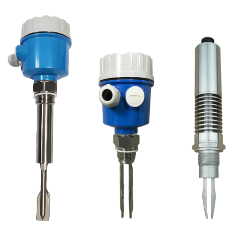
Tuning fork level switches are widely used in petrochemical, metallurgy, light industry, building materials, environmental protection and other industries to achieve the upper and lower limits of the liquid level or material level alarm and control.
A pair of piezoelectric crystals mounted on the tuning fork base causes the tuning fork to vibrate at a certain resonant frequency. When the tuning fork is in contact with the measured medium, the frequency and amplitude of the tuning fork will change, and these changes will be detected, processed and converted into a switching signal by the intelligent circuit to achieve the purpose of alarm or control.
Whether the installation of tuning fork level switches is standardised or not, it directly affects whether the later use of tuning fork level switches can be carried out safely and smoothly, and also relates to whether the production efficiency can be effectively improved. In this paper, the installation, connection and commissioning of tuning fork level switches are introduced in detail to help the field instrumentation personnel to master the tuning fork level switch installation matters needing attention, and to avoid as far as possible the occurrence of faults and accidents in the use of level switches.
Installation instructions:
1, the instrument is generally fork end down vertical installation, horizontal installation or fork end down tilt installation (when the material adhesion is strong, it is recommended to use the fork end down vertical installation).
2, the instrument is not allowed to be mounted on the back, that is, the fork end upward installation.
3、It is recommended to use vertical or inclined installation when the material is mixed with lumps or hard particles.
4、Before installing on the equipment, it is recommended to use a small amount of media samples to test the calibration sensitivity. For example: the instrument will be immersed in a container installed with media to test the reliability of the switch.
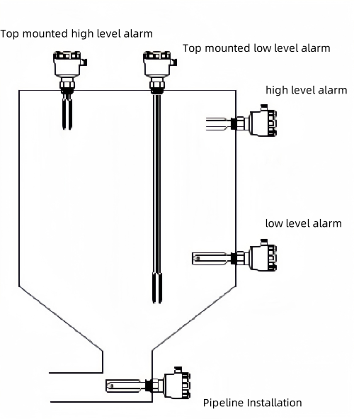
5, the actual installation is generally divided into the top of the installation (high level monitoring of the medium), side wall installation (high or low level monitoring of the medium), pipe installation (air flow monitoring of the material pump).
When installing and using, do not hold the fork strand of the instrument by hand or strike the fork strand, so as to avoid deformation of the fork strand by force, or even damage to the internal piezoelectric element.
I. Installation
1、Before installation, please reconfirm whether the model of the instrument meets the environmental requirements of the site, such as: process pressure, process temperature, chemical properties of the medium, etc., in order to ensure that the instrument can be used normally after installation.
2. Generally speaking, the tuning fork level switch can be installed horizontally, vertically or inclined in any position. However, if the measured medium is sticky, it is necessary to install the tuning fork level switch vertically to reduce or avoid the phenomenon of hanging material.
3, when installing the tuning fork level switch, should make the fork face and the liquid lift or flow to keep the same direction, you can avoid hanging material or due to the resistance of the medium to the fork body and the resulting measurement error.
4, select the tuning fork level switch installation position, should avoid the measurement error caused by the installation in the feeding port position, or even damage to the instrument. Avoid installing the switch close to the feeding port to reduce the damage to the tuning fork; if the switch must be installed close to the feeding port, please install a 4″ wide protection plate 200mm above the switch.
5、High viscosity (>2000mm2/s) liquid installation should make the tuning fork part of the barrel wall, pipe wall distance increase to no liquid adhesion.
6、For over-pressure or under-pressure containers or pipelines, must ensure that the process of connecting the integrity of the seal. Before installation, it should be confirmed that the sealing material meets the requirements of on-site process temperature and process pressure.
7, when the instrument is installed outdoors or in a humid environment, such as rain or the village in the condensation phenomenon, rain and condensation will then flow down, so before accessing the cable, please bend the cable line and lead downwards to prevent water or moisture into the instrument.
II. Connections
1、Safety tips
(a) from the safety point of view, only in the case of power failure can be wired;
(b) for explosion-proof instrument wiring must follow the relevant explosion-proof wiring requirements.
2、Access cable
The cable for the tuning fork level switch is generally a general-purpose cable with a round cross-section. The diameter of the cable cross-section is 5-9 mm, otherwise the sealing effect of the cable entrance cannot be ensured. If you need to use other specifications of the cable, please use the matching cable entrance bolt, and pay attention to the sealing performance of the cable entrance after replacement.
3、Wiring matters
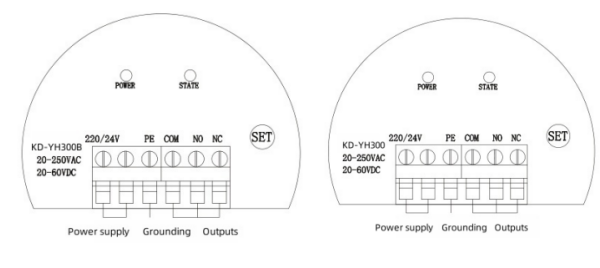
(1) Each instrument comes with a set of relay contacts (SPDT) single-pole, double-throw, the relay is only used as a switch, and cannot directly drive the alarm or other larger power equipment action. All control signals are output from the terminal block on the top of the electronic unit. When the green light is on, it indicates that the relay is working normally, and when the light is off, the relay is in an alarm state (the relay is also in an alarm state when there is a power failure or a malfunction in the instrument).
(2) open the shell cover, there are terminals, toggle switch, light-emitting diode LED, sensitivity adjustment knob. Sensitivity adjustment knob clockwise rotation, sensitivity decreases; counterclockwise rotation, sensitivity increases. Usually the factory has been well labelled without adjustment, for high viscosity liquid media, generally lower sensitivity.
III. Commissioning
1、The density adjustment switch on the control panel can change the measuring sensitivity of the tuning fork level switch to make it better adapt to the measured liquid. The density switch of the tuning fork level switch is located in the lower gear when it is shipped from the factory, and the measuring density is 0.7g/cm?; when encountering the liquid with especially low density, the density switch can be dialled up to the upper gear, and the measuring density can be up to 0.5g/cm? at this time, which makes the detection more sensitive, and the measurement more reliable.
2, for overflow protection and anti-dry operation of the two limit alarm function, need to be combined with the actual requirements of the site to adjust the instrument's high and low mode (High/Low) switch, and ultimately to achieve the signal output state required by the customer.
3、Indicator lamps for displaying switch status
1)Green = Normal working state
2)Red = Alarm status
3)Red (blinking)=fault status.
We are here to help you! If you close the chatbox, you will automatically receive a response from us via email. Please be sure to leave your contact details so that we can better assist

