 Español
  pусский
  العربية
  Português
BETTER TOUCH BETTER BUSINESS
Contact Sales at KAIDI.
Float level sensor working principle:
Float level sensor utilise Archimedes' principle to observe the liquid level by continuously measuring the load on a float rod submerged in the process liquid.
The displacer is cylindrical in shape, has a continuous cross-sectional area, and is made as long or short as desired. The normal height range is from fourteen inches to one hundred and twenty inches.
As the level increases, the float rod is subjected to greater buoyancy, making the sensing instrument appear lighter, and the sensing instrument interprets the weight loss as a rise in level and transmits a proportional O/P signal.
As the level decreases, the buoyancy force on the displacer rod decreases with a corresponding increase in weight, which is interpreted as the level detector lowering the level and then providing a proportional signal output.
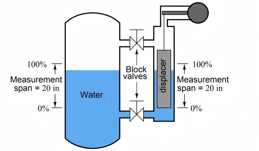
A typical float level detector installation is shown below:
Although the basic principles of operation have been outlined for a higher level than the very practical float level sensor, the structure is built to achieve a specified measurement objective through complex electronic circuitry.
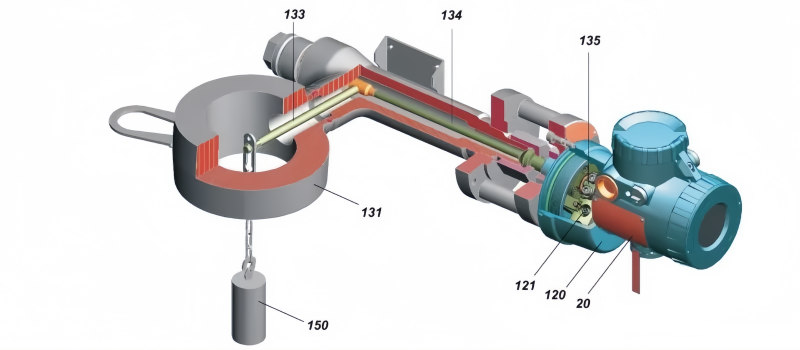
In these types of float level sensors, the float is connected to a spring that restricts movement with each increment of buoyancy (i.e., level change).
A transmitter incorporating a linear variable differential transformer (LVDT) is used to track the increase and decrease of the displacer rod as the level changes. Complex electronics then typically process the voltage signal from the LDVT into a 4-20mA o/p signal.
Archimedes' Principle Applied to Displacers
According to Archimedes' principle, the buoyancy force on a submerged object is usually equal to the load on the volume of fluid displaced by the object.
Suppose that in a magnetic float level sensor we have a cylindrical float rod with density ρ, radius r, length L and density of the method fluid У. During installation, the length of the displacer rod is proportional to the measured level:
The volume of the displacement rod, V = πr2L
The displacer level sensor shown in the figure is mounted above the vessel, and once the vessel is full, the displacer rod is completely submerged in the method fluid, so the volume of method fluid discharged is V = πr2L. Once the vessel is empty or at its lowest level, the volume of method fluid discharged V = zero
Therefore:
The buoyancy force on the float rod when the vessel is full is given by the following equation:
Buoyancy = weight of method fluid discharged
= πr2LУg (g = acceleration of gravity)
Actual weight of the displacer = πr2Lρg
Once the vessel is full, the net weight of the displacer as detected by the LVDT, transmitter and associated electronics is:
= πr2Lρg - πr2LУg = πr2Lg(ρ-У) = Vg(ρ-У)
From the above, it can be seen that the net weight detected by the LVDT is proportional to the density difference between the displacer rod (ρ) and the method fluid (У)
Therefore, the relative density of the displacer rod should be lower than the density of the measured level and the specific gravity of the fluid must be forced to be labelled.
Typical relative densities of liquids are in the range of 0.25 to 1.5 regardless of the displacement level sensor used. Another purpose worth mentioning is that the range of the displacer level gauge depends only on the length (L) of the displacer rod specified for a given application.
When the vessel is empty or the level is at its lowest, the
Buoyancy on the float = 0
Therefore, the LVDT detects a weight of = πr2Lρg
The LVDT registers a voltage signal at the minimum vessel level and outputs the corresponding signal. The displacer length is determined by the working range (span) nominal, the specific gravity of the method fluid, pressure and temperature. Factory-calculated diameters and weight-area units ensure proper operation and provide an accurate 4-20mA output.
We are here to help you! If you close the chatbox, you will automatically receive a response from us via email. Please be sure to leave your contact details so that we can better assist

