The common industrial automation instruments include flow meters and liquid level gauges,
pressure gauges, temperature gauges and so on. The standardized management and operation in the instrument construction stage is indispensable, which is the precondition to ensure the correct and stable operation of the instrument equipment. 1 Overview of instrument construction Instrument construction includes the construction of the following equipment: solenoid valve control cabinet, pneumatic actuator, electric actuator, electric valve drive device, transmitter, logic switch, temperature measuring element, liquid level gauge, flow meter, analytical instrument , Local display instruments, local incubators, local junction boxes and other equipment, as well as the laying of cable trays and cables (including various shielded cables, control cables, communication cables and optical cables, etc.) of the entire set of instruments and control equipment in the system, Cable wiring and system checking, trial operation, etc. 2 Installation of control panels, tables and cabinets (1) The installation of instrument panels and cabinets should be carried out after the civil construction is completed. When absolutely necessary, effective measures should be taken to ensure that the instrument panels and cabinets are not damaged or stained with dirt. (2) During the loading, unloading and transportation of the panel cabinet, pay attention to the brakes to prevent the dial from tipping, scratches and violent bumps. In order to prevent damage to the equipment and paint on the tray, the tray is generally transported to the installation site before unpacking. (3) Cabinets such as computers are stored in the constant temperature warehouse, and the cabinets taken out from the constant temperature warehouse should be installed in time and cannot be left in the open air environment. (4) Check the unpacked cabinet, including whether the equipment is complete, whether there are missing parts, damage, etc. (5) During the installation and transportation of the dial, a thick rubber pad is laid on the ground to protect the ground and equipment, and the dial is transported horizontally by a manual hydraulic forklift. (6) An isolation layer should be erected around the local enclosure and sealed with a plastic sheet. The sealing tape cannot be directly attached to the panel, and the enclosure cannot be used as a toolbox. (7) Turn on the temporary power supply of the heater for drying immediately after it is in place, send a special person to check it regularly, and make a maintenance record. (8) The holes of the dial cable should be blocked at any time to prevent the intrusion of dust, moisture and small animals. (9) After the installation of the dials in the unit control room and the electronic equipment room, send a special person to be on duty 24 hours a day. 3 Installation of the air system for the instrument (1) When laying the pipeline, the thermal expansion of the main equipment should be considered. (2) When the pipeline is laid horizontally, a certain slope should be maintained. (3) The laying of pipelines should be neat and beautiful, and crosses and turns should be reduced. (4) When the pipeline is connected to the instrument, the joint must be aligned and not subject to mechanical stress. (5) After the pipeline is laid, it should be checked, and there should be no leakage, blockage and misconnection. (6) The pipeline in front of the instrument valve should be tested for working pressure. (7) Signs with serial numbers and names should be hung at both ends of the pipeline after construction. (8) The installation of equipment should be easy to maintain and repair. 4 Installation of electric and pneumatic actuators (1) The actuator must be installed firmly, without shaking during operation, and without being corroded by soda water and rain. When the operating handwheel of the actuator is turned clockwise, the adjustment mechanism is closed. When the operating handwheel is turned counterclockwise, the adjustment mechanism is opened. The adjustment mechanism from fully closed to fully open should correspond to the full stroke of the actuator. (2) For the outdoor part of the actuator, a rain cover should be installed to prevent the sun and rain and prolong the service life. (3) Take corresponding protective measures for the installed and debugged actuators to prevent damage to paint and accessories. (4) The direction of the arrow on the valve should be consistent with the direction of the flow of the medium, the inlet and outlet of the gas source should be checked accurately, and the inlet must be equipped with a pressure reducing valve and a filter. (5) After the installation is completed, cover the positioner, feedback mechanism, solenoid valve, etc. with a dust cover, and take protective measures to prevent the finished product from being polluted. 5 Installation scheme of thermal control source components Determine the position of the sampling opening according to the requirements specified in the regulations. The steam medium opening is between the horizontal angle of 45°, the water and oil medium opening is the horizontal downward angle of 45°, the gas medium opening is the vertical upper part of the pipeline and the 45° angle between the two sides. . 5.1 Temperature (1) The measuring element shall not be installed in the dead corners of pipes and equipment. (2) The temperature measuring element should be installed in a place free from severe vibration and impact. If it is in a hidden place, its terminals should be led to a place that is convenient for maintenance. (3) For the temperature measuring element installed horizontally, if the insertion depth is greater than 1 m, measures should be taken to prevent the casing from bending. (4) The temperature measuring element installed on the pulverized coal pipeline should be equipped with a large protective cover to be removed to prevent damage to the element. 5.2 Pressure (1) To measure the pressure of the gas-powder mixture, a pressure-taking device with a separator and an anti-blocking and purging device should be used. (2) The diameter of the pressure-taking aperture of the wind pressure should be equal to the outer diameter of the pressure-taking device to prevent clogging. The pressure-taking device should have a purging plug and a detachable pipe joint. (3) The end of the pressure source part shall not exceed the inner wall of the main equipment or pipeline (except for the measurement of dynamic pressure), and both the sampling hole and the source part shall be free of burrs. 5.3 Flow (1) Check and measure the appearance of the installed throttle and the diameter of the orifice, and make a record.And meet the design and national standards. (2) The roundness of the pipeline where the throttling is installed should be measured on the throttling piece and within the downstream 2D length. (3) Use the pressure equalizing ring to take pressure, the pressure taking holes should be evenly arranged on the same section, and the number of upstream and downstream pressure taking holes must be equal. 5.4 Liquid level (1) The position of the liquid level measuring point should be selected at a place where the medium working condition is stable, and should be consistent with the measuring range.
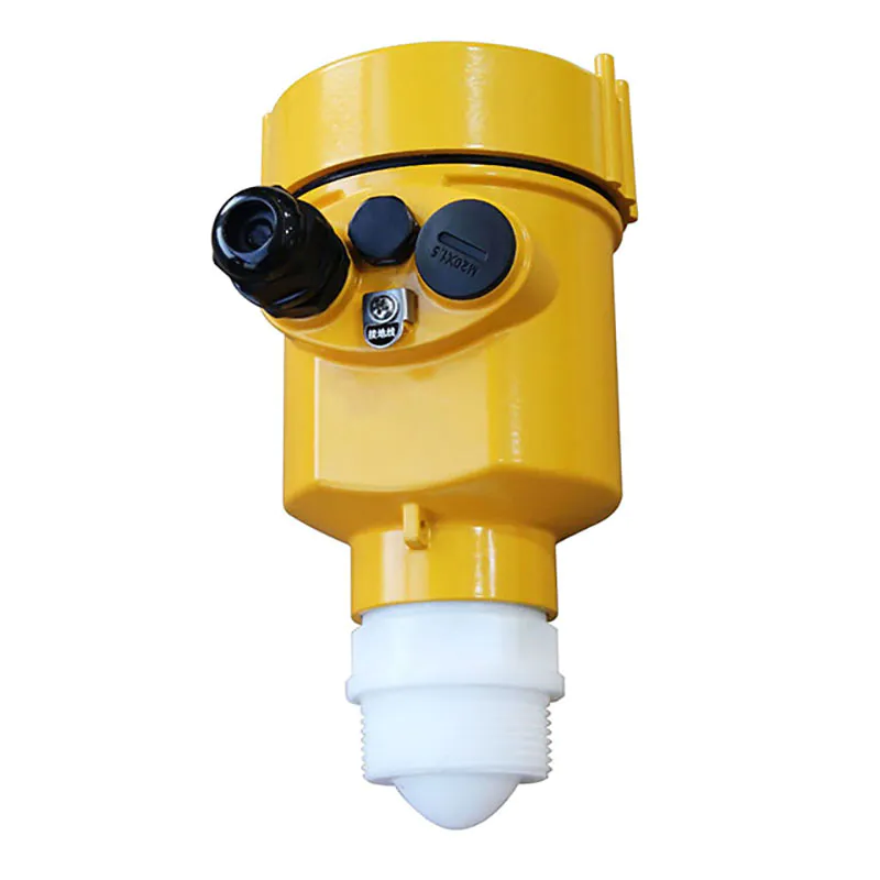
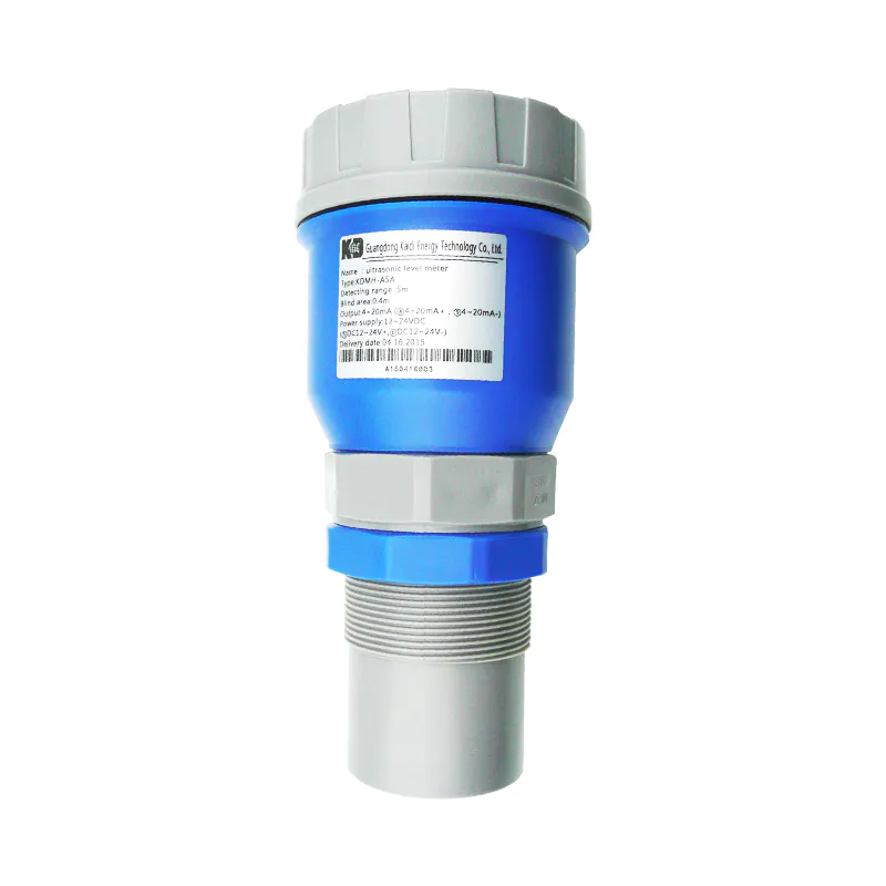
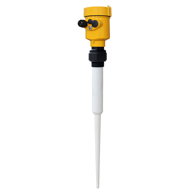
Guangdong Kaidi Energy Technology Co., Ltd. has an array of branches in domestic for munufacturing level gauge.
customized level indicator are the in thing today. To buy a for yourself do visit Guangdong Kaidi Energy Technology Co., Ltd. at Kaidi level indicator.
Visit Kaidi level indicator for the best in customized level indicator level gauge supplies and get the most cost effective for your level gauge solution. Design and customization are also welcomed.
The success of level gauge of campaigns largely rides on how you market your company to the crowd.
 Español
  pусский
  العربية
  Português