 Español
  pусский
  العربية
  Português
BETTER TOUCH BETTER BUSINESS
Contact Sales at KAIDI.
I. Differential pressure transmitter working principle:
Fluid flow through the pipeline throttle device, the formation of local contraction at the throttle, so that the flow rate increases, the static pressure decreases, so the formation of pressure drop, that is, the differential pressure, the media flow the larger the flow rate, before and after the throttle device produces a greater pressure difference, so the differential pressure flowmeter can be measured by measuring the pressure difference in order to measure the size of the fluid flow.
Differential pressure flowmeter consists of a primary device and a secondary device. Primary device called flow measurement element, which is installed in the measured fluid pipeline, resulting in a pressure difference proportional to the flow rate (flow rate) for the secondary device for flow display. Secondary device called display meter. It receives the differential pressure signal generated by the measuring element, and will be converted to the corresponding flow rate for display. Differential pressure flowmeter primary device is often a throttling device or dynamic pressure measurement device (Pitot tube, homogeneous tube, etc.). Secondary device for a variety of mechanical, electronic, combined differential pressure meter with a flow display instrument. Differential pressure sensitive components of the differential pressure gauge are mostly elastic components. As the differential pressure and flow rate is square root relationship, so the flow rate display instrumentation are equipped with a square device in order to linearize the flow rate scale. Most of the instruments are also equipped with flow accumulation device to display the cumulative flow for economic accounting. This method of measuring flow using differential pressure level indicator has a long history, more mature, countries around the world are generally used in more important occasions, accounting for about 70% of the various electromagnetic flow measurement methods. Power plant main steam, feedwater, condensate and other flow measurement are used in this meter.
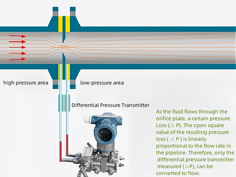
The measured medium flow rate is proportional to the open square of the differential pressure. Most meters also have a flow accumulation device to display the cumulative flow for economic accounting.
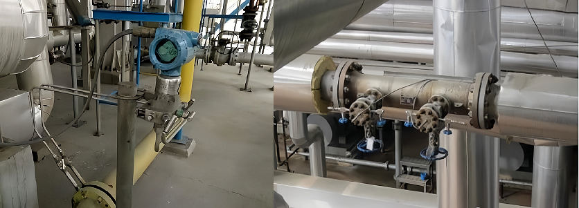
Structure:
Throttling element: A device installed in the pipeline to generate differential pressure level indicator.
Pressure conduit: Takes the differential pressure generated before and after the throttling device and transmits it to the pressure transmitter.
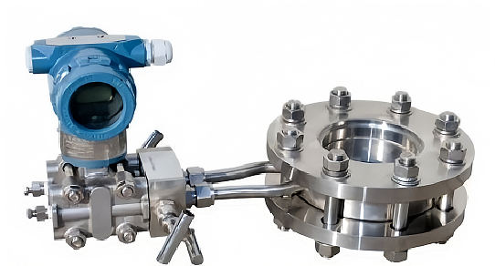
Differential pressure transmitter: The differential pressure generated is converted into a standard electrical signal (4~20mA or FF).
Valve set:
Used to connect the pressure guide tube with the differential pressure transmitter assembly to prevent the membrane box from being damaged by the single cavity pressure when the transmitter is put into operation.
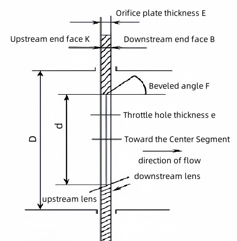
Due to the different geometrical profiles of the throttling elements, the different ways of taking pressure and the different specific technological conditions of the application, the specific structures of the throttling devices are also varied.
Standard throttling device: according to the unified standard regulations for the design, production and installation of the standard differential pressure device, do not have to go through individual calibration can be used.
Non-standard throttling device: refers to the test data is not very sufficient, design and production must be individually calibrated to use the differential pressure device.
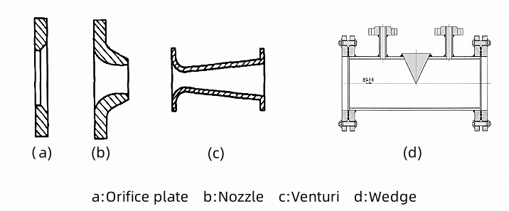
Common standard throttling devices: standard orifice plates, standard nozzles, classic venturi, venturi nozzles
Common types of differential pressure flow meters in industry
Orifice plate flowmeter, balance flowmeter, wedge flowmeter, Aniuba flowmeter, Venturi flowmeter and so on.
Common Differential Pressure Flow Meter Throttling Elements
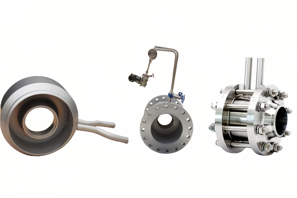
(standard orifice plate)
(Wedge Type Throttle Elements)
(Venturi throttle)
Valve manifolds
Differential pressure flowmeter connection commonly used valve group has three valve group and five valve group.
Three-valve group and five-valve group put into use steps:
1, open the balance valve, so that the high and low pressure side at the same time under pressure
2、Open the high pressure side shut-off valve
3、Close the balance valve
4、Open the low-pressure side shut-off valve
Note: When opening the high and low pressure side shut-off valve, you should first loosen a circle to confirm that the instrumentation side of the connection is not leaking before the valve is fully open.
Steps for deactivating three-valve and five-valve manifolds:
1、Close the low-pressure side shut-off valve
2、Open the balance valve
3、Close the high-pressure shut-off valve
4、Close the balance valve
Note: The operating principle of the three-valve group is to avoid heat or one-way pressure on the measuring instrument, and not to let the isolation fluid in the guide tube or isolation tank disappear.
II. Features and applications of differential pressure flow meter
Orifice plate flowmeter:
The structure is easy to copy, simple, solid, stable and reliable performance;
Wide range of applications, including all single-phase fluids (liquid, gas, steam);
Narrow range, the general range of degrees only 3:1 ~ 4:1;
There are longer straight pipe length requirements before 10D after 5D;
Pressure loss;
Corrosion, wear and tear, scaling, dirt sensitive, long-term use of precision is difficult to guarantee
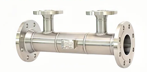
Balance flow meter
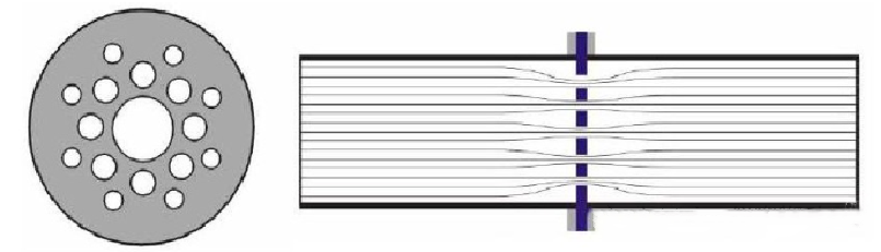
Low straight pipe section requirements, as low as 0.5D before and 0.5D after;
Low permanent pressure loss;
Long service life;
Wide measuring range;
Simple installation;
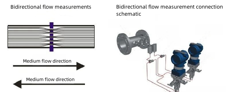
Measurement of bidirectional flow
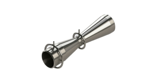
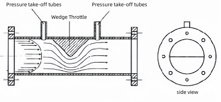
Wedge Flow Meter
Suitable for low viscosity large flow, high viscosity small flow fluids;
Unique structure, no deposition, no clogging, wide range of application, especially for high viscosity, crystallization mixture, dirty liquids, for DN25-DN1200 pipeline;
Straight pipe section requires 5D before and 2D after;
Bidirectional flow can be measured;
Good abrasion resistance, high precision in long-term operation, easy installation and maintenance;
III. Installation matters and requirements of differential pressure flow meter:
1, before and after the installation of the original throttle straight pipe section in differential pressure transmitter working principle, the longer the better, but the actual project is not possible, in order to ensure that the throttle original before 10D after 5D;
2, throttle original opening center needs to be concentric with the pipe centerline, the deviation shall not exceed 1 degree;
3, the installation of the orifice plate, to determine the direction of the orifice plate throttling member with the pipeline media direction in line with the orifice plate reverse installation will cause the flow rate indication becomes smaller;
4, the flow beam in the pipeline should be stable;
5, the measured medium in the flow through the throttle device should not occur phase change;
6, for the newly installed piping system must be flushed in the pipeline before the installation of the throttle device
Commonly Used Pressure Taking Methods
Angle connection pressure taking: applicable to: standard orifice plate, nozzle
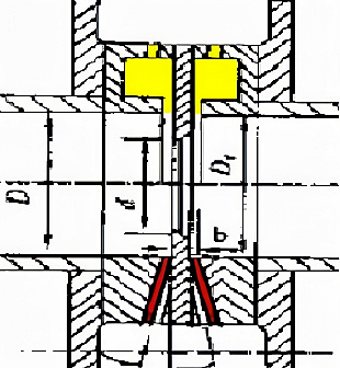
Two pickup ports are mounted at an angle upstream and downstream of the throttling element. The upstream and downstream pickup tubes are located at the front and rear end faces of the orifice plate (or nozzle). Angle pickup includes separate drilling and ring chamber pickup. Individually drilled holes are used in DN400 and above caliber occasions, generally for the ring chamber pressure extraction.
Flange pressure extraction: applicable to: standard orifice plate, wedges
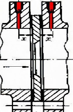
The distance between the axes of the upstream and downstream pressure-taking holes and the end faces of the upstream and downstream sides of the orifice plate is 25.4±0.8mm (1inch). Pressure-taking holes are opened on the flanges of the upstream and downstream sides of the orifice plate.
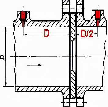
Diameter taking pressure: applicable to: standard orifice plate (large diameter), long diameter nozzle
The distance from the axis of the upstream pressure-taking hole to the upstream end face of the orifice plate is 1Dm±0.1Dm, and the distance from the axis of the downstream pressure-taking hole to the downstream end face of the orifice pole is 0.5Dm.
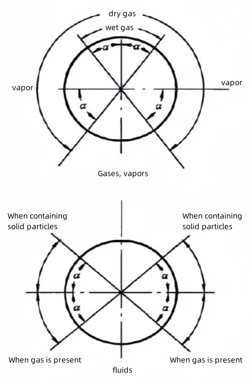
Installation of the pressure take-off port
When measuring gas flow, in the upper half of the process piping, as shown in the figure.
When measuring liquid flow, in the lower half of the process piping within 0~45° angle with the horizontal centerline of the process piping, as shown in the figure.
When measuring steam flow, in the upper half of the process piping within 0~45° angle from the horizontal centerline of the process piping, as shown in Fig.
We are here to help you! If you close the chatbox, you will automatically receive a response from us via email. Please be sure to leave your contact details so that we can better assist

