 Español
  pусский
  العربية
  Português
BETTER TOUCH BETTER BUSINESS
Contact Sales at KAIDI.
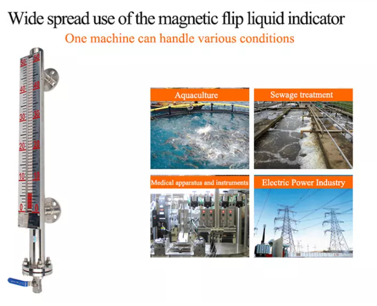
Detailed explanation of on-site calibration method of magnetic flip column liquid level gauge
The biggest feature of the magnetic flip column level gauge is its intuitiveness. People can easily and intuitively observe the liquid level in the tank by visual inspection without any other means, and the current one can be matched with the magnetic flip column. There are also more technical means. Some data with a measurement range of more than 2 meters in production are often no worse than differential pressure transmitters. Its application in actual production is becoming more and more extensive, and its role is also subject to more and more. people's attention.
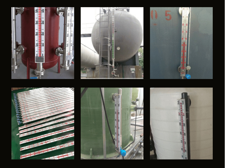
However, since the conditions of the measurement site are very different, there are many aspects that need to be paid attention to how to obtain the most accurate data in different measurement sites. This paper takes a side-mounted liquid level gauge with an electrified remote signal (4~20mA) as an example to discuss a simple and effective on-site calibration method, in order to measure the liquid level error and uncertainty of the entire system under on-site installation conditions. purpose, has practical significance.
According to the description of the national verification regulations, the liquid level gauge below 2m needs to be verified by the standard water tank device, and if it exceeds 2m, it needs to be verified by the simulation method. However, due to the limitation of the size of the large-range magnetic flip-column liquid level gauge itself, there are problems in the installation of the liquid level gauge over 2m in the laboratory, and the regulations do not specify the simulation verification method.
So can this type of liquid level gauge achieve online calibration? To sum up, the following problems need to be solved:
The density range of the medium measured by the liquid level gauge is often wide, generally 0.8~1.2g/cm3, how to correct the influence of density on the measurement error of the liquid level gauge;
The on-site storage tank is like a black box, how to determine the liquid level reference point for calibration is a key issue;
The installation of the liquid storage tank cannot be absolutely vertical, so how to choose the measuring standard and how to measure it will be very important.
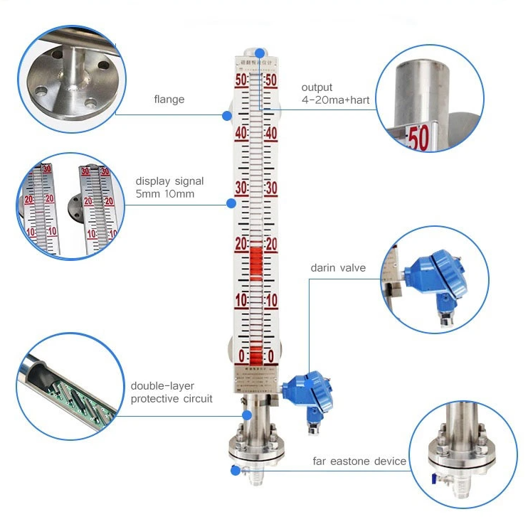
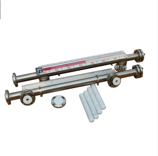
Before introducing the specific steps of on-site calibration, let's review the structural principle of the magnetic flip column level gauge; the magnetic flip column level gauge is developed based on the principle of buoyancy and magnetic coupling. When the liquid level in the container to be tested rises and falls, the magnetic float in the body tube of the liquid level gauge also rises and falls. The permanent magnet in the float is transmitted to the magnetic flip column indicator through magnetic coupling, and drives the red and white flip columns to flip so as to realize Clear indication of liquid level.
Through the opening and closing of the built-in reed switch contacts, the transmission of current or voltage signals is realized. Magnetic flip-column liquid level gauges are generally adjusted by the simulation method (not described in this method specification) when they leave the factory to ensure that they match the actual medium when supplied.
The specific steps of on-site calibration include:
* First determine the density of the medium
The density of the medium can be measured with a standard density meter, or it can be obtained according to the specific information provided by the user. The density of the medium needs to be recorded and recorded to ensure that the density of the medium can meet the requirements of the liquid level meter instruction manual. Although the medium density has an influence on the indication value of the liquid level gauge in theory, the zero position and full scale value of the liquid level gauge can be directly adjusted by the potentiometer in actual use.
*Secondly determine the reference zero point
Measure the inner diameter D of the connecting pipeline with a vernier caliper, and determine a lower ruler point of the standard liquid level on the upper part of the tank body, if conditions permit; it is best to grind it into a groove to prevent the sounding gauge from swinging, and make a mark;
Manually inject water into the storage tank without pressure in the tank, stop the water injection when the water level is slightly higher than the water level gauge inlet pipe, open the manual ball valve E at the lower connecting flange port and loosen the tank body and the liquid to be calibrated The connecting flange F between the level gauges (do not remove, so that the water flow does not overflow) until there is no surging flow in the pipeline, close E, and remove the flange; when the liquid in the tank is stable, open E, and then wait for the dripping flow. Status, stable for 1min (if necessary, it can be drained through the drain valve to improve the detection efficiency);
Use the depth sounding steel tape measure to measure the distance ha from the measuring point to the water surface, the actual zero empty height h0=ha-D/2, this state is the zero point of the liquid level gauge measurement
*Again the calibration of each liquid level point
Install the flange, close E, and continue to fill the tank with water until the column turns over to indicate the main scale of the liquid level to be calibrated. After the water surface is stable, measure the output current li and the water level hi. The actual liquid level is: HO=h0- hi=ha-D/2-hi; continue the measurement of other points until full scale.
*The fourth is the adjustment of the zero point and full scale of the liquid level
While determining the reference zero point, adjust the zero point potentiometer so that the output electrical signal is displayed as 4mA; the full scale adjustment is performed at the upper limit of the standard liquid level, and the full star range potentiometer is adjusted to make the output electrical signal display as 20mA. If there is a deviation in the output during the downstroke measurement, please refer to this method to adjust. Field calibration requires repeating the above steps for three return measurements.
*Other issues and methods that need attention
The instruments used for on-site calibration are simple and practical, and have strong operability. In the case that the liquid medium cannot be directly contacted, if the inclination of the tank body is small and the surface of the measuring point is level, a laser range finder can also be used to replace the depth sounding steel tape. Suitable for liquid level calibration of pressurized vessels or volatile media.
We are here to help you! If you close the chatbox, you will automatically receive a response from us via email. Please be sure to leave your contact details so that we can better assist

