 Español
  pусский
  العربية
  Português
BETTER TOUCH BETTER BUSINESS
Contact Sales at KAIDI level gauge manufacturer.
Overview
IFD-IR(UV)-111(C) explosion-proof integrated flame detector is a new type of intelligent flame detector with communication function, which is a new product independently developed by our company following the development trend of the latest international flame detecting products and accumulating years of experience in the production of fire detecting equipments and on-site debugging of fire detecting equipments. It is mainly applicable to the detection of flame signals of boiler burners with explosion-proof function when fuel oil, blast furnace gas and coke oven gas are the main fuels.
IFD-IR(UV)-111(C) flame detector is a microprocessor-based intelligent integrated flame detector that combines fire detection probe and signal amplifier into one. This series of products has the characteristics of beautiful appearance, reliable work, small volume, strong function and so on. In the design, taking into account the nature of the flame signal in the furnace chamber and the influence of changes in the strength of the flame signal on the detector, in the hardware and software design.
The measures have been taken in the design of the system. The product can be interconnected with the FSSS system, but also through its own host computer software to form a separate flame detection system. This series of products can be convenient to replace the imported fire detection products, can also be used to upgrade the traditional fire detection products.
uses
IFD-IR(UV)-111(C) Flame-proof Integrated Flame Detector is mainly suitable for detecting the flame signal of boiler burner with natural gas, flare gas, coke oven gas, light oil and other main fuels on site.
It can be widely used in the burners of large, medium and small boilers in petroleum, chemical, metallurgy, paper making and other industries.
specificities
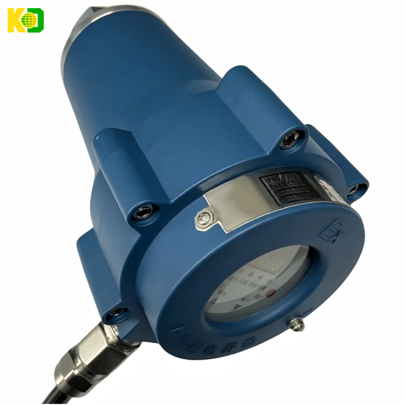
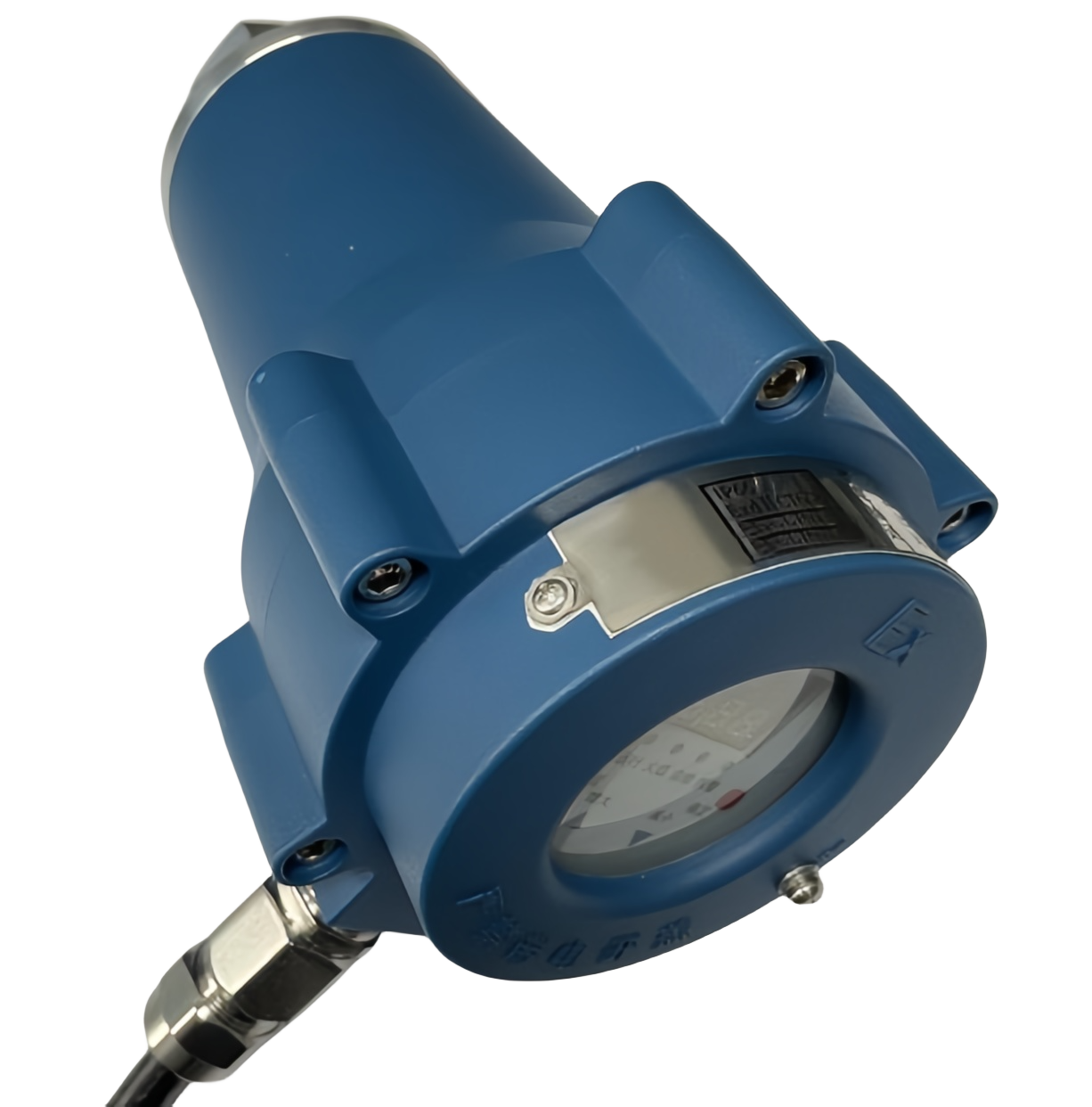
▶Integrated structure, convenient for on-site installation, eliminating the fire detection amplifier cabinet, saving space and reducing investment.
▶Shell protection grade IP66, suitable for all kinds of harsh working conditions.
▶Shell explosion-proof grade Exdb Ⅱ CT6Gb, can be applied to a variety of dangerous occasions
▶Internal temperature detection, with over-temperature alarm function
▶Touch keyboard or RS485 communication interface, all parameters can be set through the local, on-site/remote multiple methods
▶Professional configuration and debugging software, with convenient and flexible operation interface in English and Chinese.
Main technical indicators
1.Mechanical parameters
a. External dimensions: D (maximum diameter) × L (length)
Note: 1. D=156mm
2、For flangeless products, L=213.5mm
3、For short flange products, L=236.5mm
4、For long flange products, L=260.5mm
b. Shell material adopts metal die-casting aluminium, weight ≤3kg
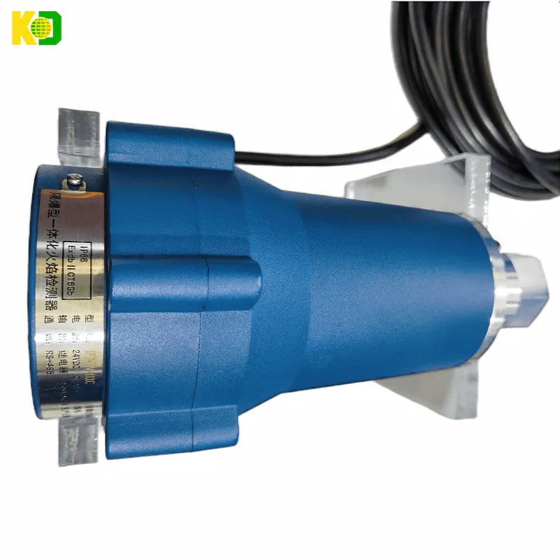
The appearance of the IFD-IR(UV)-111(C) explosion-proof integrated flame detector is shown in Figure 1:
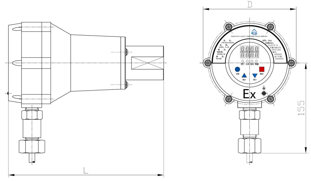
Fig. 1 Dimensional drawing of the appearance of the fire test
2. Working environmental conditions
a. Temperature range: -40°C to +75°C (IFD-IR(UV)-111C) -20°C to +60°C (IFD-UV-111)
b. Relative humidity: 0%~95% non-condensing
c. Atmospheric pressure: 86kPa~108kPa
d. Cooling/blowing air requirements:
Air source: clean, dry, low temperature
Flow rate: The required cold air flow rate is 25.5Nm3/h, accessed by a 3/8" threaded connection on the mounting flange.
Air pressure: properly exceeding the pressure of the furnace chamber or air box is sufficient
3、Technical parameters
a. Response wavelength: 850nm ~ 1700nm (IFD-IR-111C)
190nm~600nm (IFD-UV-111C)
185nm~260nm (IFD-UV-111)
b. Input power supply: 24VDC±10%
c. Operating current: ≤200mADC
d. Power consumption: ≤5W
e. Electrical connection: 12-core coloured, flame-retardant, low-smoke, shielded cable for direct connection
f. Relay output: flame relay, SPST (normally open)
Alarm Relay, SPST (Normally Closed, Normally Open)
Contact capacity: MAX: 3A, 250VAC (resistive load)
g. Analogue output: 4mA~20mADC, maximum connected load: 750Ω
h. Status display: 8-bit digital tube and 4-bit light-emitting diode display
i. Keyboard input: 4-digit touch keypad
j. Cable specification: 12-core coloured, flame retardant, low smoke, shielded cable
k. Data communication: communication mode: RS485 (controllable type)
Baud rate: Adjustable
Communication distance: ≤1300 metres
Number of connected nodes: ≤128
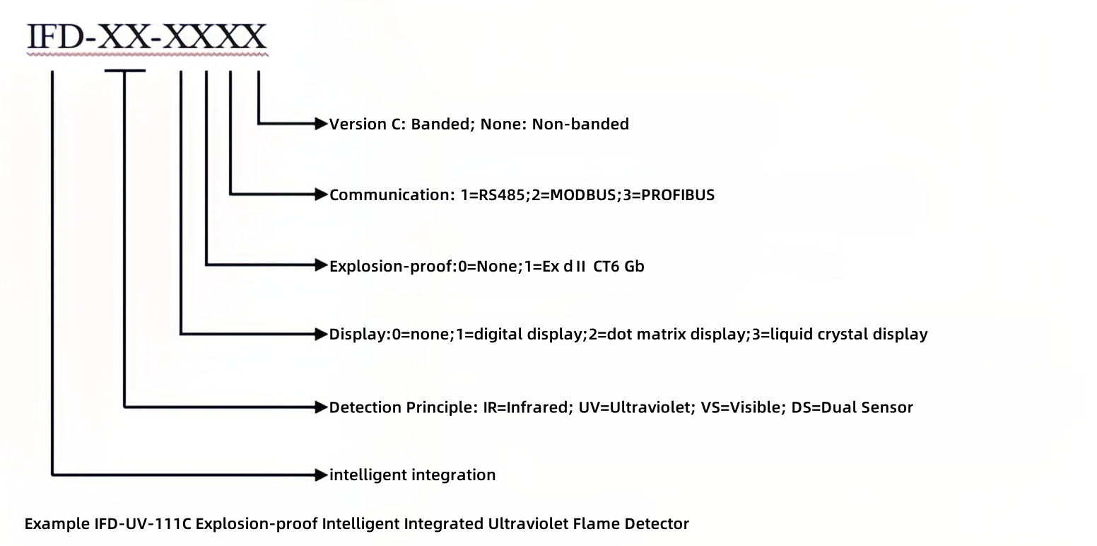
Model Code
mounting
1. Electrical installation
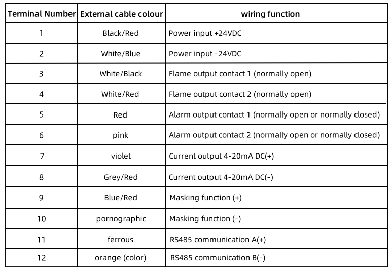
Product wiring cable (coloured 12-core) description, see Table 1:
2. Mechanical installation
The installation is divided into two types: external and internal peeping, as shown in Figures 2 and 3:
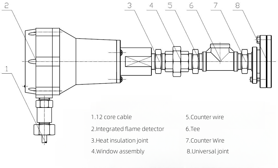
Fig. 2 Schematic diagram of external peep installation
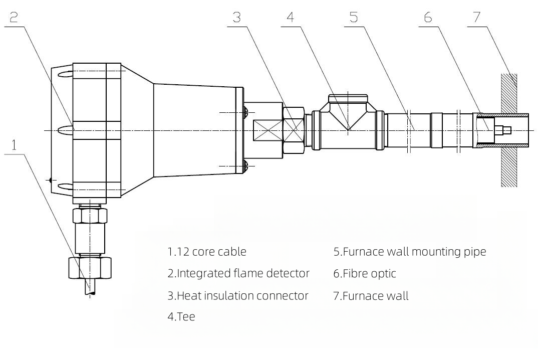
Figure 3 Schematic diagram of endoscopic installation
VII. Methods of use
1. Definition of terms
a. Flame intensity: refers to the intensity of the signal from the boiler burner flame transformed by the sensor and amplified by the amplifier.
b. Flame gain: refers to the amplification of the flame intensity signal of the detector.
c. Flame threshold: refers to the minimum value set by the detector to have a fire, i.e. the threshold of having a fire,Refers to the maximum value set by the detector for no fire, i.e., the no-fire threshold.
d. With fire delay time: in normal operating conditions detector power in the working state, flame input signal is valid, the detector from no fire to have a flame signal and stimulate the flame relay output this process time, that is, with fire delay time.
Flame signal and stimulate the flame relay output the process of time, that is, the fire delay time.
e. Flame response time: under normal operating conditions the detector is powered on in the working state, when the flame signal disappears, the detector flame relay
State are in a delay time to remain unchanged, the delay time that the fire response time.
f. Maximum alarm temperature: the detector set the maximum temperature of the internal work, when the detector's operating temperature ≥ the set temperature, the detector automatically
Alarm
2、System operation status
The system operation status screen is shown below:
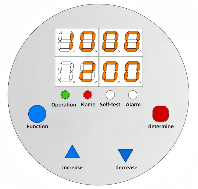
Brief description of the working process:
When the system is in operation, the keypad is locked, the "Run" lamp lights up, the system dynamically detects and displays the flame intensity as well as the fire threshold.
The system dynamically detects and displays the flame intensity and the fire threshold.
When the flame is effective (flame intensity > fire threshold) and the duration exceeds the fire delay time, "Flame" lamp lights, flame relay output is effective (normally open contact closed).
When the flame is effective (flame intensity > fire threshold and the duration exceeds the fire delay time, the "flame" lamp lights up, the flame relay output is effective (normally open contact is closed), the current output is the corresponding value (4mA-20mA DC), and the system starts the self-checking function automatically according to the time to be set.
When the self-test time arrives, the "self-test" lamp lights up, and at the same time detects whether the probe, the system interface is normal and whether the system is over-temperature or not, when the system fails or the system is over-temperature, the "self-test" lamp lights up.
When the system is faulty or the system is over-temperature, the "Alarm" lamp lights up, the alarm relay output is effective (normally open and closed, normally closed and open), and the system remembers the type of alarm. The system remembers the alarm type.
The system reopens by pressing the "Function" key 2 times continuously.
In the flame effective running state ("running", "flame" lamp is lit), press the "OK" key, then the manual self-test function, the system manual self-test mechanism and automatic self-test.
The mechanism of self-test is the same as that of automatic self-test.
When the flame is invalid (flame intensity < no fire threshold) and the duration exceeds the flame failure response time, the "flame" lamp goes out, the flame relay output is invalid, and the current output is in line with the intensity.
When the flame is invalid (flame intensity <no flame threshold and duration exceeds the flame out response time), the "flame" lamp goes out, the flame relay output is invalid, the current output is the value corresponding to the intensity (4mA-20mA DC), and the self-test function stops.
In the flame invalid operation state ("operation" lamp lit, "flame" lamp off), press the "OK" key, artificial self-test function is invalid.
When the external wiring (12-pole) terminal No. 9, No. 10 line shorted, the system for the masking function - forced to no fire state: no flame switch effective output, current output and intensity of the
Switch effective output, current output and intensity of the corresponding value (4mA ~ 20mA DC), flame lamp out. The system alarm function is normal.
3、System Setting Status
When you need to set the system parameters, press the "Function" key, which is the background 4-digit digital tube display "---- ", prompting the input of
The system password is displayed as "-hundred and ten", the "Increase" key becomes the function key for adjusting the number, each time it is pressed, it increases by 1, and it cycles between 1 and 9.
The "Decrease" key becomes the right shift key, each time you press it, the display will cycle in hundred, ten, one, one hundred respectively, when a certain bit is valid, the bit will flash. When the password is entered correctly, the system automatically enters the setting state.
When the password is entered correctly, the system automatically enters the setting state.
When entering the system setting state, different display characters are used to represent the setting of different parameters, and the characters are displayed on the leftmost side of the background digital tube area.
The meaning is as follows:
(1), Flame Roughing --------- -- "C"
(2), AC gain --------- -- "A"
(3), DC gain --------- -- "Γ"
(4), file type --------- --- "E"
(5), with fire threshold --------- --- "b"
(6), without fire threshold --------- --- "d"
(7), upper frequency threshold --------- -- "upper c
(8), the lower frequency limit --------- -- "Lower C
(9), logic selection --------- -- "Upper "
(10), with fire delay time --------- "F"
(11), flame out response time -------- "H "
(12), self-test time --------- - "L"
(13), current factor --------- - "Lower O"
(14), Damping factor --------- - "Upper O"
(15), temperature setting --------- - "U"
(16), password setting --------- - "-"
(17), communication address --------- - "P"
(18), baud rate setting --------- "S"
(19), System version --------- - "Upper U"
Parameter setting operation instructions
〈1〉、Flame coarse adjustment
When entering the flame coarse adjustment setting state, the upper digital tube at any time to display the actual flame value, the lower digital tube on the left side of the display "C", the right side of the flame coarse adjustment value.
Display the flame coarse adjustment value, each time you press the "increase" key to increase 1, the maximum value of 5; each time you press the "reduce" key to reduce 1, the minimum value of 1; the default value of the system is 1.
The default value is 1. The flame coarse adjustment value 2-5 means the flame is 2-5 times of the coarse adjustment value 1 (default value). Press "Increase" or "Decrease" key, the flame intensity value will do the same when you press "Increase" or "Decrease" key.
When pressing "Increase" or "Decrease" key, the flame intensity value will be changed accordingly, and the maximum flame value is 1000, after the setting is completed, you can press "OK" key to enter into the system running state, or press "OK" key to enter into the system running state.
After setting, you can press "OK" key to enter the system operation status, or press "Function" key to enter other parameter setting menu. Each time you press the "increase" or "decrease" key, the system will automatically store the number of presses.
The system automatically stores the number of presses each time the "increase" or "decrease" key is pressed (with the function of power-down storage, the same below). When the system parameter setting is completed but do not press the "OK" key, the system delays for a certain period of time (1M).
After a certain time delay (1M), the system will automatically return to the running state, the keyboard will be locked automatically, and the system will run according to the new parameters (the same below).
〈2〉、AC Gain
When entering the AC gain setting state, the upper digital tube at any time to display the actual flame value, the lower digital tube on the left side of the display "A", the right side of the flame gain value.
Display the flame gain value, each time you press the "increase" key increase 1, the maximum value of 100; each time you press the "decrease" key decrease 1, the minimum value of 0;
When pressing "increase" or "decrease" key, the flame intensity value will be changed accordingly, and the maximum flame value is 1000; after the setting is completed, you can press "Confirm" key to enter the system operation.
After setting, you can press the "OK" key to enter the system operation state, or press the "Function" key to enter other parameter setting menu. Each time you press the "Increase" or "Decrease" key, the system will automatically store the value (the value of the key).
The system automatically stores the pressed value (with power-down storage function, the same below). When the system parameter setting is completed but do not press the "OK" key, the system
After a certain time delay (1M), the system will automatically return to the running state, the keypad will be locked automatically, and the system will run according to the new parameters (the same below).
〈3〉、DC Gain
When entering the DC gain setting state, the upper line of digital tubes at any time to display the actual flame intensity value, the lower line of digital tubes on the left side of the display "Γ", the right side of the flame DC gain value.
The right side displays the flame DC gain value, each time you press the "increase" key to increase 1, the maximum value is 100; each time you press the "decrease" key to decrease 1, the minimum value is 0; press the "increase" key to decrease 1, the minimum value is 0; press the "decrease" key to decrease 1, the minimum value is 0.
When pressing "increase" or "decrease" key, the flame intensity value will be changed accordingly, and the maximum flame background value is 1000.
When the setting is finished, press "OK" key to enter the system operation state, or press "Function" key to enter other parameter setting menu.
〈4〉、Document type
When entering the file type setting state, the upper digital tube at any time to display the actual flame value, the lower digital tube displays the left most "E", the right display file type value, each time you press the "increase" key to increase 1, the maximum value of 10; each time you press the "decrease" key to decrease 1, the minimum value of 10.
When entering the file type setting state, the upper line digital tube displays the actual flame value at any time, the leftmost side of the lower line digital tube displays "E", and the right side displays the value of file type, every time you press the "Increase" key to increase by 1, the maximum value is 10; every time you press the "Decrease" key to decrease by 1, the minimum value is 0.
After setting, you can press "OK" key to enter the system operation status, or press "Function" key to enter other parameter setting menu. Each time you press "Increase" or "Decrease" key, the minimum value will be 0.When the "small" key is pressed, the system automatically deposits the pressed value (the same below).
〈5〉、Fire threshold
When entering the fire threshold setting state, the upper digital tube at any time to display the actual flame value, the lower digital tube on the left side of the display "b", the right side of the display of the fire threshold value.
Display the fire threshold value, each time you press the "increase" key increase 4, the maximum value of 999; each time you press the "decrease" key decrease 4, the minimum value of 20.
After setting, you can press the "OK" key to enter the system operation status, or press the "Function" key to enter other parameter setting menu. Each time you press the "Increase" or "Function" key to enter other parameter setting menu.
Increase" or "reduce" key each time you press, the system automatically deposits the value of the press (the same below).
〈6〉、No fire threshold
When entering the no-fire threshold setting state, the upper digital tube displays the actual flame value at any time, and the leftmost digital tube displays "d", and the right side displays the no-fire threshold value.
Display the no-fire threshold value, each time you press the "increase" key to increase 4, the maximum value of the fire threshold value -20; each time you press the "reduce" key to reduce 4, the minimum value is 0. After the setting is completed, you can set the actual flame value at any time.
After setting, you can press "OK" key to enter the system operation status, or press "Function" key to enter other parameter setting menu. Each time
Each time you press the "increase" or "decrease" key, the system automatically deposits the value (the same below).
〈7〉 Frequency upper limit
When entering the upper limit of frequency setting state, the upper digital tube displays the actual flame value at any time, and the left side of the lower digital tube displays "upper c", and the right side displays the upper limit of frequency setting value.
The left side of the lower digital tube displays "upper c", and the right side displays the set value of the upper frequency limit, each time you press the "increase" key to increase 1, the maximum value of 200; each time you press the "decrease" key to decrease 1, the minimum value of 10; press the "decrease" key to decrease 1, the minimum value of 10.
The maximum value of flame is 1000; when pressing "increase" or "decrease" key, the flame value will change accordingly.
After setting, you can press "OK" key to enter the system operation state, or press "Function" key to enter other parameter setting menu.
〈8〉、Lower frequency limit
When entering the lower frequency limit setting state, the upper digital tube displays the actual flame value at any time, the left side of the lower digital tube displays "lower c", and the right side displays the lower frequency limit setting value.
The left side shows "lower c", the right side shows the lower frequency limit setting value, each time you press the "increase" key increase 1, the maximum value of 180; each time you press the "decrease" key decrease 1, the minimum value of 1; press the "decrease" key decrease 1, the minimum value of 1; press the "decrease" key decrease 1, the minimum value of 1.
When pressing "increase" or "decrease" key, the flame value will be changed accordingly, and the maximum flame value is 1000; after setting, press "OK" key.
After setting, you can press the "OK" key to enter the system running state, or press the "Function" key to enter the other parameter setting menu.
〈9〉、Logic selection
When entering the logic of choice setting state, the upper digital tube at any time to display the actual flame value, the left side of the lower digital tube shows "on the ", the right side shows the logic of the setting value, each time you press the "OK" key to enter the system operation state, or press the "function" key to enter other parameters setting menu.
The right side of the display logic set value, each time you press the "increase" key increase 1, the maximum value of 1; each time you press the "reduce" key decrease 1, the minimum value of 0. Setting
After finishing the setting, press "OK" key to enter the system operation state, or press "Function" key to enter other parameter setting menu.
This function needs to cooperate with the fault relay contact output: when the set value is "0", the fault relay contact output converter socket A1 K. G is connected via jumper; when the set value is "0", the fault relay contact output converter socket A1 K. G is connected via jumper,
When the set value is "0", K and G of the fault relay contact output change-over socket A1 are connected via a jumper; when the set value is "1", B and G of the fault relay contact output change-over socket A1 are connected via a jumper;
Factory setting "0": K, G of the fault relay contact output change-over socket A1 are connected via jumper!
Note: The fault relay is located on the circuit board on the inside of the dome-shaped housing and is labelled with the component "A1". The outside of the component is labelled "B. G. K",
G, K" on the outside of the element!
〈10〉、Fire delay time
When entering the fire delay time setting state, the upper digital tube displays the actual flame value at any time, the leftmost side of the lower digital tube displays "F", and the right side displays the value of the fire delay time.
The right side shows the value of fire delay time, each time you press the "increase" key increase 1, the maximum value of 6 seconds; each time you press the "decrease" key decrease 1, the minimum value of 1 second.
The minimum value is 1 second. Setting is complete, you can press the "OK" key to enter the system running state, or press the "Function" key to enter the other parameters of the setup menu.
〈11〉Fire-out response time
When entering the flame failure response time setting state, the upper digital tube at any time to display the actual flame value, the left side of the lower digital tube shows "H", the right side shows the flame failure response time.
The right side shows the value of flame failure response time, each time you press the "increase" key to increase 1, the maximum value of 6 seconds; each time you press the "decrease" key to reduce 1, the minimum value of 1 second.
The minimum value is 1 second. Setting is complete, you can press the "OK" key to enter the system running state, or press the "function" key to enter the other parameter setting menu.
〈12〉Self-test time
When entering the self-test time setting state, the upper digital tube at any time to display the actual flame value, the lower digital tube on the left side of the display "L", the right side of the self-test time value.
Display self-test time value, each time you press the "increase" key increase 1, the maximum value of 3 minutes; each time you press the "decrease" key decrease 1, the minimum value of 1 minute.
The minimum value is 1 minute. Setting is complete, you can press the "OK" key to enter the system running state, or press the "function" key to enter the other parameters of the setup menu.
〈13〉Flame intensity coefficient adjustment
When entering the flame intensity coefficient setting state, the upper line of digital tubes at any time to display the actual flame value, the lower line of digital tubes on the left side of the display "0", the right side shows the flame intensity coefficient value, the right side shows the flame intensity coefficient value.
The right side shows the flame intensity coefficient value, each time you press the "increase" key increase 1, the maximum value of 100 (i.e., 100 per cent); each time you press the "decrease" key decrease 1, the minimum value of 10 per cent.
key is pressed, the maximum value is 100 (i.e. 100%); each time the "decrease" key is pressed, the minimum value is 10 (i.e. 10%). The flame intensity coefficient is used to adjust the current output to prevent wide fluctuations in the output current. The system
If the maximum value of coefficient is 100%, the maximum value of flame intensity 1000 corresponds to 20mA, if the coefficient is set to 60%, the maximum value of flame 600 corresponds to 20mA.
After setting, you can press the "OK" key to enter the system operation state, or press the "Function" key to enter the other parameter setting menu.
Setting menu.
〈14〉、Adjustment of damping coefficient
When entering the damping coefficient setting state, the upper digital tube displays the actual flame value at any time, and the leftmost side of the lower digital tube displays "0", and the right side displays the damping coefficient value.
The left side of the lower digital tube displays "up 0", the right side displays the value of damping coefficient, every time you press the "Increase" key to increase 1, the maximum value is 100; every time you press the "Decrease" key to decrease 1, the minimum value is 1.
The damping coefficient is used for current filtering output. After setting, you can press "OK" key to enter the system operation state, or press "Function" key to enter other parameter setting menus.
Other parameter setting menu.
〈15〉 Temperature Setting
When entering the temperature setting state, the left 2 bits of the upper digital tube displays the highest temperature value in history, and the right 2 bits displays the instant temperature detection value, and the leftmost part of the lower digital tube displays "temperature", and the leftmost part displays "temperature".
The left side of the digital tube displays "U", the right side displays the temperature setting value, each time you press the "increase" key increase 1, the maximum value of 85 ℃; each time you press the "decrease" key decrease 1, the maximum value of 85 ℃; each time you press the "decrease" key decrease 1, the maximum value of 85 ℃.
Each time you press "Increase" key to increase 1, the maximum value is 85℃; each time you press "Decrease" key to decrease 1, the minimum value is 60℃. Setting is complete, you can press the "OK" key to enter the system running state, or press the "function" key to enter the other parameters of the setting menu.
Other parameter setting menu.
〈16〉Password Setting
When entering the user password setting state, the upper digital tube displays the actual flame value at any time, and the left most digital tube displays "-", and the right displays "***".
"****" the actual password value, at this time the meaning of the display is "hundred and ten", "increase" key to adjust the number of function keys, each time you press the increase of 1, 1
The "Increase" key becomes the function key for adjusting the number, increasing 1 each time it is pressed, and cycling between 1-9. "Decrease" key becomes the right shift key, each time you press the display were in the hundreds, tens, individuals, hundreds of cycles, a certain bit is valid, the bit flashes.
When a bit is valid, the bit flashes. Maximum combination of 9 * 9 * 9, after the completion of the settings can be pressed "OK" key to enter the system running state, or press the "function" key to enter the other
parameter setting menu. The default password of the system is "111".
〈17〉、Communication address
When entering the communication address setting state, the upper digital tube displays the actual flame value at any time, the leftmost display of the lower digital tube "P", the right side of the communication address value.
Display the communication address value, each time you press the "increase" key to increase 1, the maximum value of 127; each time you press the "reduce" key to reduce 1 second, the minimum value of 0.
Setting is completed, you can press the "OK" key to enter the system running state, or press the "Function" key to enter the other parameter setting menu.
〈18〉 Baud rate setting
When entering the baud rate setting state, the upper digital tube displays the actual flame value at any time, and the leftmost side of the lower digital tube displays "S", and the right side displays the baud rate value.
baud rate value, each time you press the "increase" key, the background area digital tube shows the corresponding value, the maximum value is 576; each time you press the "decrease" key, the background area digital tube shows the corresponding value, the maximum value is 576; each time you press the "decrease" key, the background area digital tube shows the corresponding value, the maximum value is 576.
Each time the key "Increase" is pressed, the digital pipe in the background area displays the corresponding value, and the maximum value is 576; each time the key "Decrease" is pressed, the digital pipe in the background area displays the corresponding value, and the minimum value is OFF (communication function is invalid). The significance of the values displayed in the background area is as follows:
Digital pipe display value Corresponding baud rate (bps)
OFF Invalid communication
048 4800
096 9600
144 14400
192 19200
024 2400
384 38400
576 57600
After the setting is completed, you can press the "OK" key to enter the system operation status, or press the "Function" key to enter other parameter setting menu. System default
The system is considered OFF (i.e. the communication function is invalid).
〈19〉、Masking function
When the detector's flame input signal is masked, i.e., the terminal 9 (+), 10 (-) two-point shorting so that the detector can not receive flame
Input signal, the analogue output of the detector is 4mADC ± 1mADC.
〈20〉、System software version number
When entering the system software version number display state, the upper line of digital tubes at any time to display the actual flame value, the lower line of digital tubes on the left side of the display "on the U", the right side shows the system software version number value.
The right side displays the value of system software version number. At this time, the digital tube display is read-only, press the "increase", "reduce" key are invalid. When finished, you can press the
"OK" key to enter the system running state, or press the "Function" key to enter other parameter setting menu.
VIII. Care and maintenance
In the process of using the detector, attention should be paid to the care and maintenance. The power supply voltage should be within the specified range and try to avoid large fluctuations, it is strictly prohibited to input AC voltage; the working environment should meet the specified conditions of use.
It is strictly prohibited to input AC voltage; the working environment should meet the specified environmental conditions. If the detector is found to work abnormally, it should be replaced in time to avoid further expansion of the fault.
If the detector is found to work abnormally, it should be replaced in time to avoid further expansion of the fault.
IX. Transport and storage
Packaging and transport of the flame detector is carried out in accordance with the provisions of the product packaging and transport instructions. Detector storage should be in the ambient temperature of -10 ℃ ~ +40 ℃.
+40 ℃, relative humidity of not more than 85%, well-ventilated room for safekeeping; the surrounding environment should not contain corrosive substances and gases on the product.
We are here to help you! If you close the chatbox, you will automatically receive a response from us via email. Please be sure to leave your contact details so that we can better assist

