 Español
  pусский
  العربية
  Português
Related Products


|
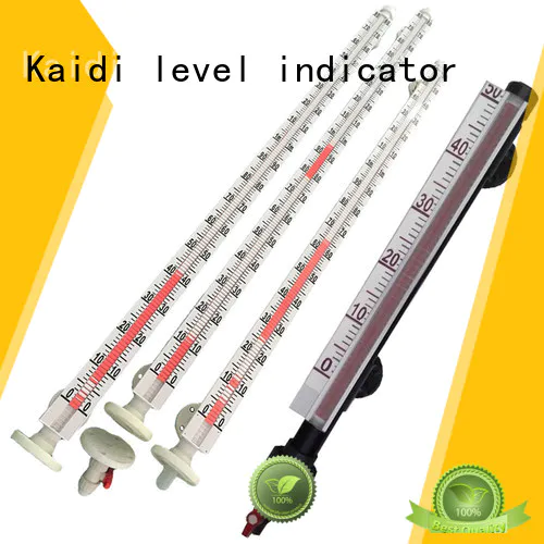
A change of level in the process tank corresponds to a similar change within the KDMLI chamber. In response to the level movement, the KDMLI float moves accordingly, actuating the flags or shuttle for visual indication.
*Numerous chamber styles (or configurations) for each design. Custom designs available.
*Complete range of level switches and level transmitters, including Eclipse Guided Wave Radar
*Fabricated, non-magnetic chamber assembly produced in a wide range of metal and plastic materials
*ANSI and EN 1092 process connections available
*Precision manufactured float with internal magnets and magnetic flux ring
*Flag or shuttle type indicator with stainless steel scale to measure height, volume, or percentage of level
*Standard float stop springs at top and bottom of chamber
*Exceptional code qualified welding
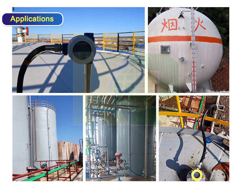
*Feed water heaters , Industrial boilers
*Oil/water separators *Flash drums, Surge tanks
*Gas chillers *Deaerators
*Blowdown flash tanks
*Hot wells *Vacuum tower bottoms
*Alkylation units
*Boiler drums
*Propane vessels, Storage tanks
1. A side-mounted level gauge and a top and bottom pipette of the container under test * are equipped with a shut-off valve to open or close the level gauge, on the other hand, it is convenient to maintain the level gauge. When the upper and lower stop valves are closed, the drain flange at the bottom of the level gauge can be opened or the drain screw can be removed, and the body of the level gauge can be cleaned by pouring water.
2. When installing the liquid level gauge, the verticality of the flange center is ‰ 4 ‰. When the measuring range of the liquid level gauge is greater than 3 meters, you need to consider adding an intermediate reinforcement flange (or ear climbing) as a fixed support to increase the strength.
3. The connection between the supporting remote level gauge transmitter and the secondary meter requires the cross-sectional area of the core wire to be greater than 0.8mm2. When laying parallel to the AC power source, the distance should be at least 20 cm. * Laying through iron pipes alone, or using shielded two-core cables, the shield can only be grounded at one end.
4. The liquid level controller is selected, and its contact capacity is designed with a resistive load. If a non-resistive or high-power load is used, an intermediate relay is used to switch.
5. For liquids containing suspended impurities and magnetically-affinitive substances, this level gauge should not be used (because these impurities will cause blocking of the float assembly).

We are here to help you! If you close the chatbox, you will automatically receive a response from us via email. Please be sure to leave your contact details so that we can better assist

