BETTER TOUCH BETTER BUSINESS
Contact Sales at KAIDI level gauge manufacturer.
Measuring Principle
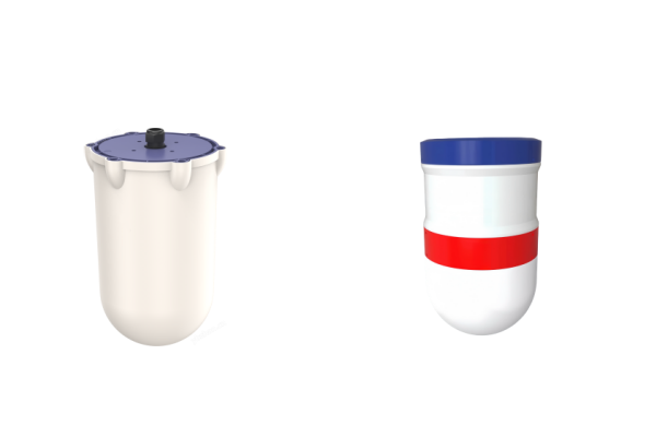
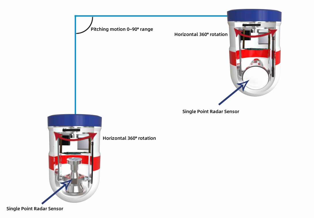
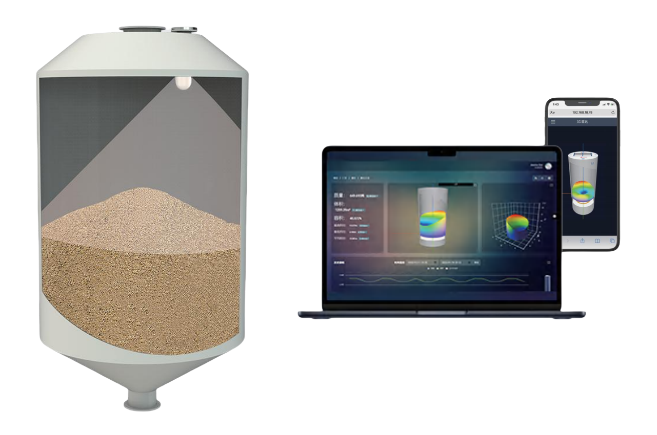
Based on terahertz frequency-modulated continuous wave (FMCW) ranging, the kaidi 3DPro2300 radar scanner drives its radar sensor to rotate in multiple dimensions by means of internal horizontal rotation and pitch structure to scan the surface of storage tanks and materials inside the tanks in a high-resolution omnidirectional manner. When the radar sensor reaches a predetermined angle, it emits microwave signals from its antenna. The microwave signals are reflected upon encountering the measured object and received by the antenna. The radar sensor is then rotated to the next predetermined angle, completing the measurement of the entire detection cycle. This process obtains the level measurement information corresponding to each angle during the entire detection cycle. By combining the angle information, the level measurement information, and the installation position of the kaidi 3DPro2300 radar scanner, calculations and processing are performed, integrating image processing, big data analysis, AI artificial intelligence, machine learning, and 3D point cloud conversion to establish a three-dimensional spatial coordinate system and obtain three-dimensional point cloud coordinate values. This allows for the presentation of three- dimensional visual images and the calculation of volume, mass, level, and other related parameters.
Product Advantages
360 ° imaging with 16200 scanning points for high-precision measurement
kaidi 3DPro2300 Radar Scanner adopts a rotating mechanical structure that combines horizontal 360 ° and elevation ± 90 °. It sends out 16200 measurement signals for scanning and detection, and draws a true and accurate three-dimensional shape of the materials in the warehouse. Based on the three-dimensional coordinates, the lowest, highest, average, mass, and volume levels are calculated to form data reports for each moment, Compared to 3D radar that emitsmeasurement signals from several fixed angles or dozens offixed angles, it greatly improves detection resolution and accuracy, making measurement data more accurate.
Full cover
For 3D radar scanner that emit measurement signals from several or dozens of fixed angles, when the material surface is low, there may be some measurement signals reaching the side wall of the silo at certain angles, resulting in a decrease in the measurement signal for detecting the surface level of the material and a reduction in effective measurement points. Moreover, when the material surface is high, there will be a relatively concentrated area of measurement signals reaching the material surface at various angles, causing no measurement signal outside the area, Both can cause three-dimensional shape distortion, and the 3DPro2300 Radar Scanner can emit measurement signals from thousands of angles, covering the surface of materials comprehensively when the material level is high or low.
Humanized design makes installation more convenient maintenance costs lower
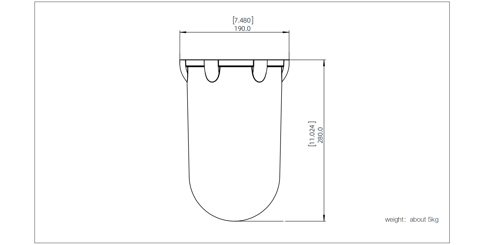
The installation hole size of the kaidi 3DPro2300 Radar Scanner can be as low as 190mm, which can minimize the impact of holes on the structural strength of the silo. And the device is equipped with a status indicator light and temperature sensor, which can rotate with the rotating mechanism and emit different colors according to the working status of the device, making it convenient for workers to observe the status of the device at a glance; When the temperature sensor detects that the working environment temperature of the equipment is too high, it stops working to avoid irreparable faults and save after-sales costs. The upper computer interface can also remind the staff that the equipment needs to be manually intervened or monitored due to high temperatures when it stops working.
High reliability, strong compatibility, and equipped with installation self correction
kaidi 3DPro2300 Radar Scanner adopts dual power supply, dual network port communication, and redundant design of communication and power supply to improve the reliability of the equipment. In the event of a fault in one channel, another channel can be used. When there is a deviation in the assembly angle of the components ofthe3DPro2300 Radar Scanner, or when there is a certain tilt angle after installation on the top of the warehouse, the internal angle meter configured can detect the angle deviation and automatically correct it through software algorithms. The upper computer software of the kaidi 3DPro2300 Radar Scanner can run on Linux and Windowssystems, allowing customers to enjoy the advantages of Linux system being free, open source, secure, stable, and multi platform.
A number of technologies are protected by patents, and have won many awards
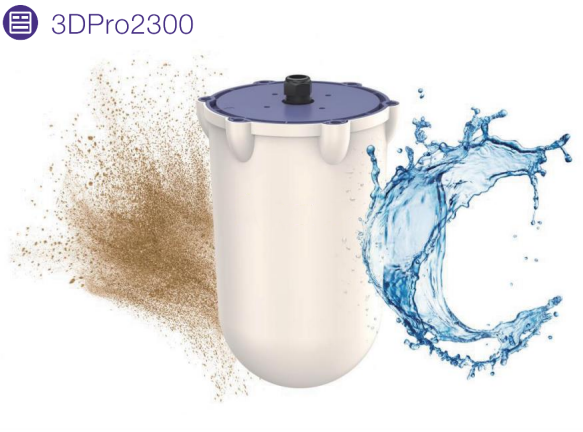
kaidi 3DPro2300 radar scanning robot has obtained appearance patents, a number of utility models and invention patents, the patent right is clear, there will be no infringement of patents, customers can rest assured that use. And kaidi 3DPro2300 radar scanning robot has obtained a number of domestic and international awards

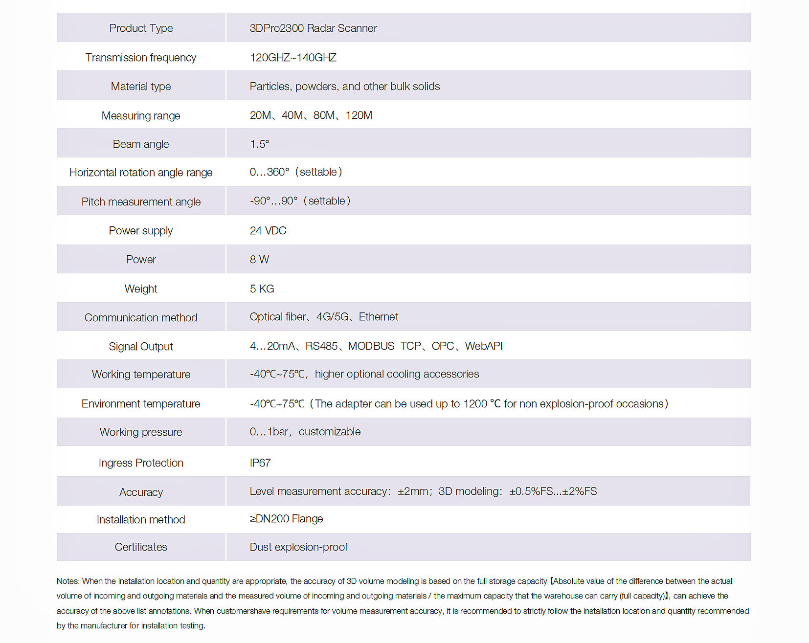
Instrument Profile
Installation Diagram
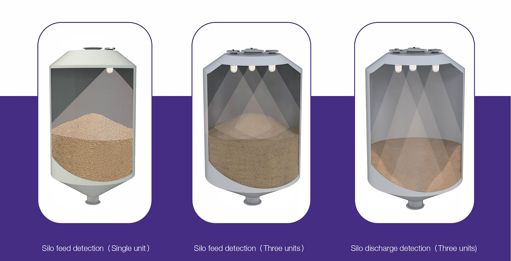
For small silos, one 3D radar scanner can be installed on each silo. For large silos, multiple 3D radar scanners can be installed on each silo. Each 3D radar scanner is responsible for scanning and detecting a fixed area. The upper computer software has a splicing and registration algorithm to stitch and register the scanning results of each 3D radar scanner in the detection area, forming a complete detection result in the area, And ultimately presented in a three-dimensional diagram.
Installation
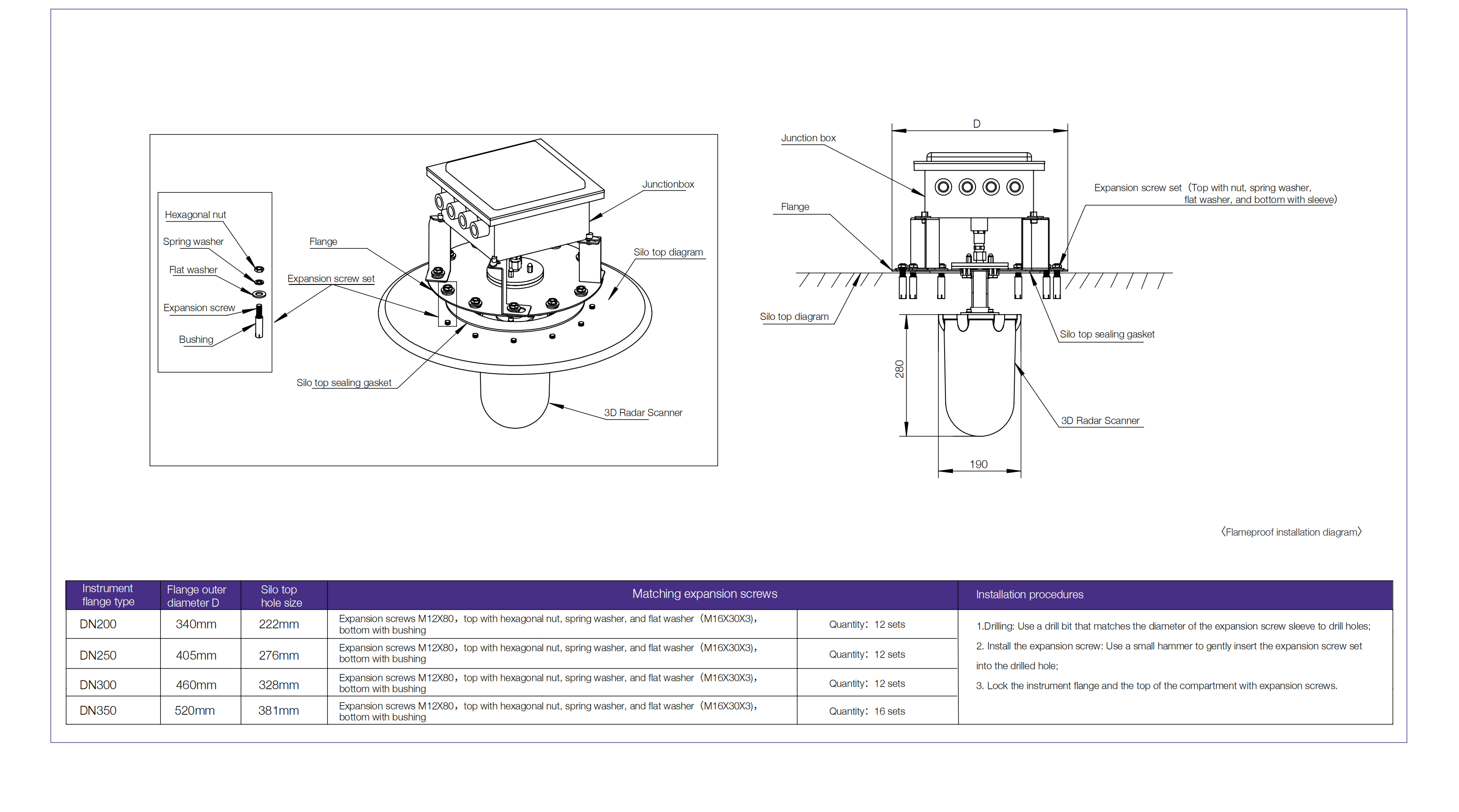
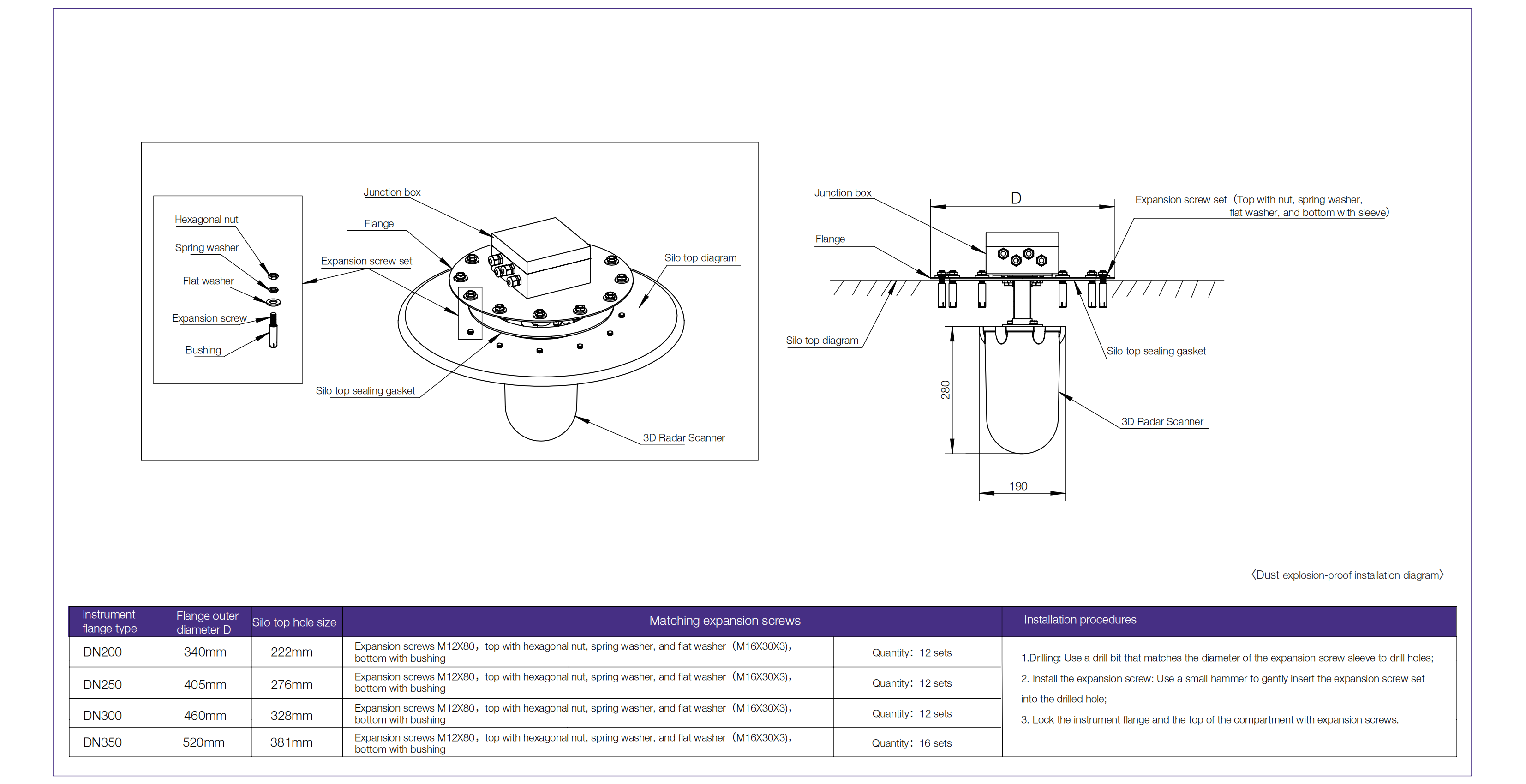
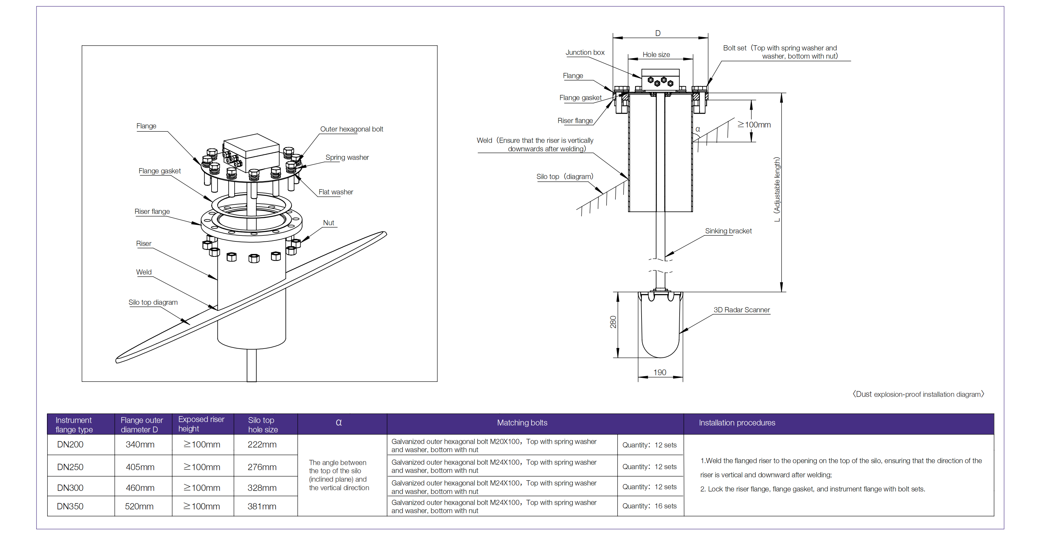
The top of the silo is flat
(1)The top of the flat silo is a steel plate structure, and after the top of the silo is perforated, it is directly welded to the riser and installed and fixed.
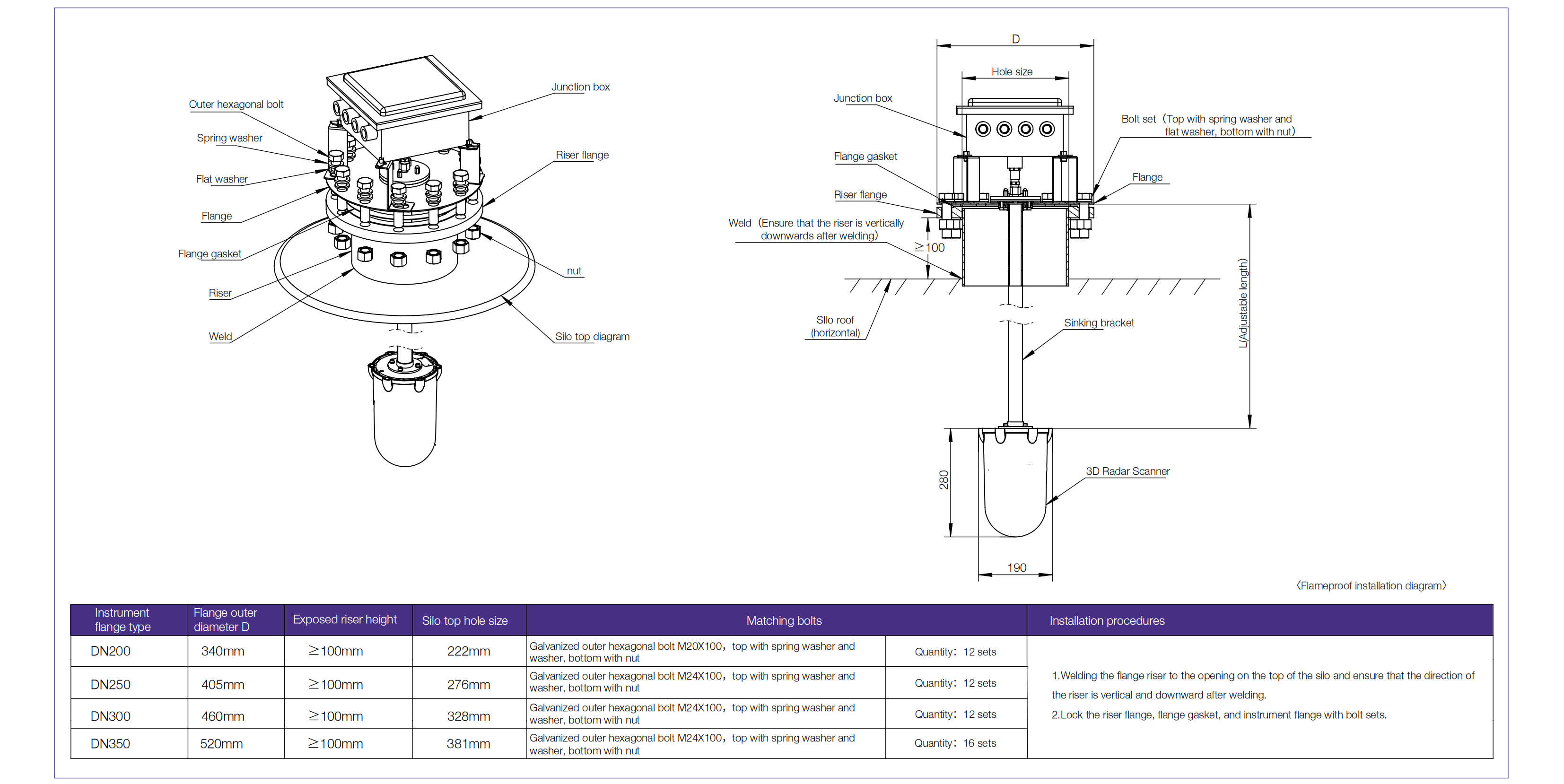
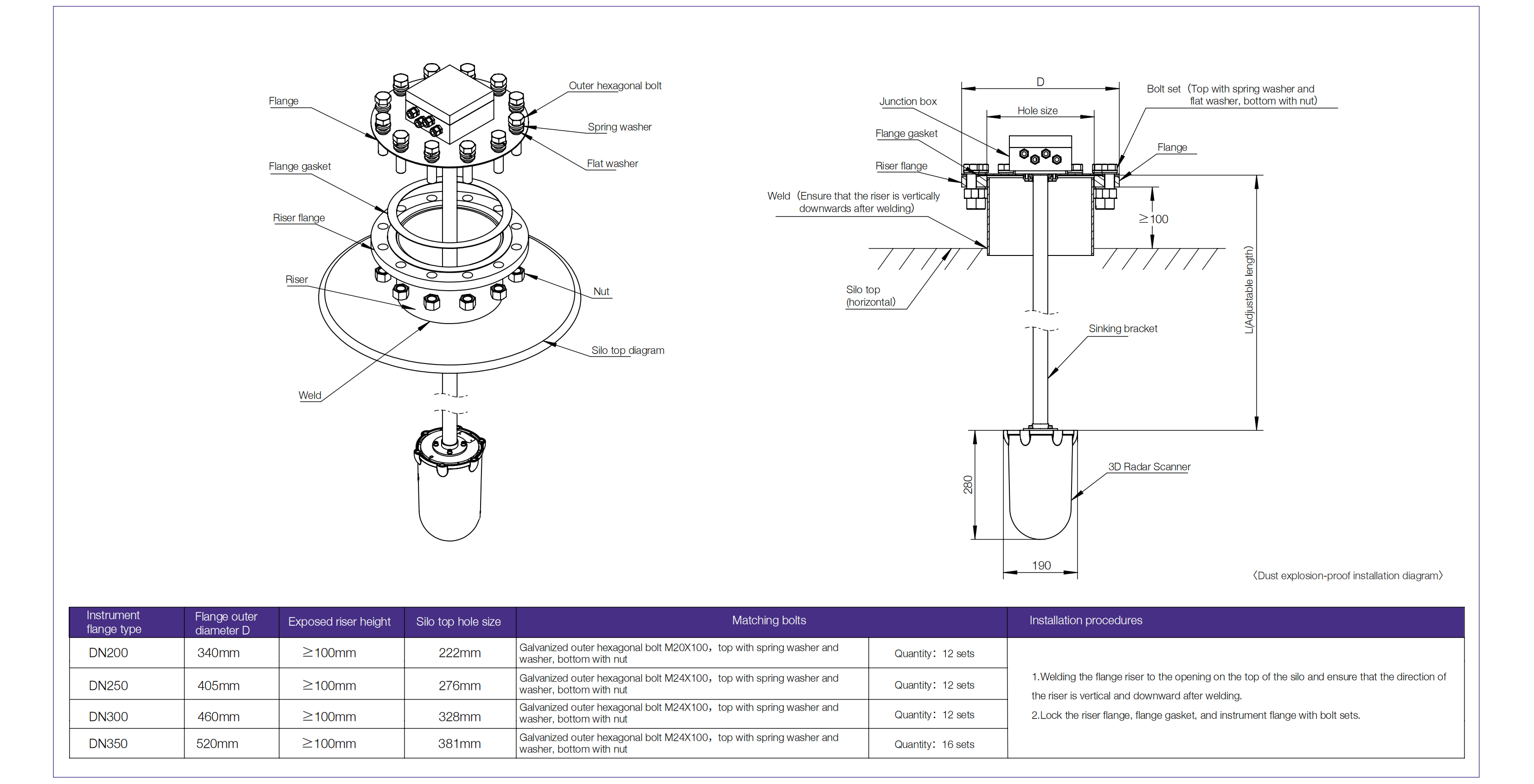
(2)The top of the flat silo is a steel plate or concrete structure, and after the silo top is perforated, it is directly installed and fixed with
the instrument flange through bolts.
Note : This installation method needs to consider the sealing problem between the instrument flange and the silo top.
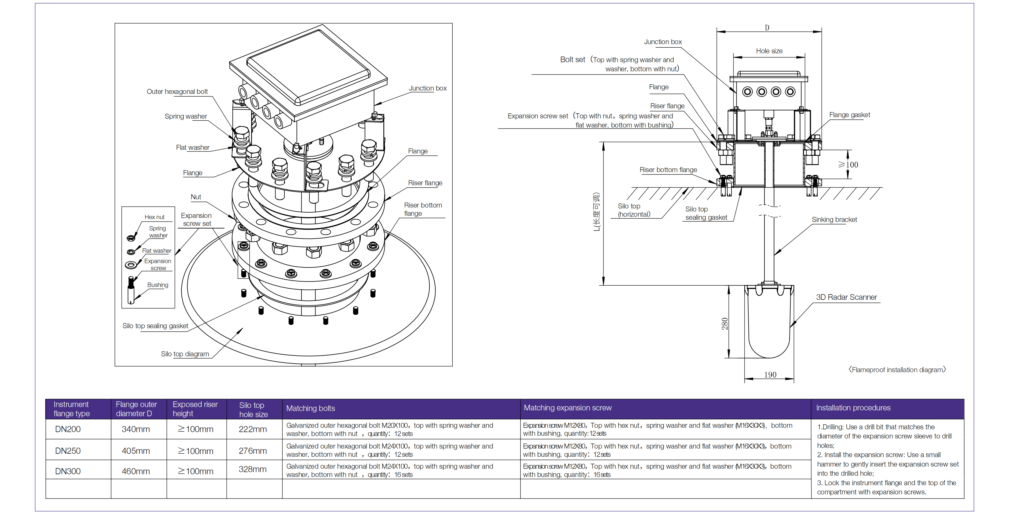
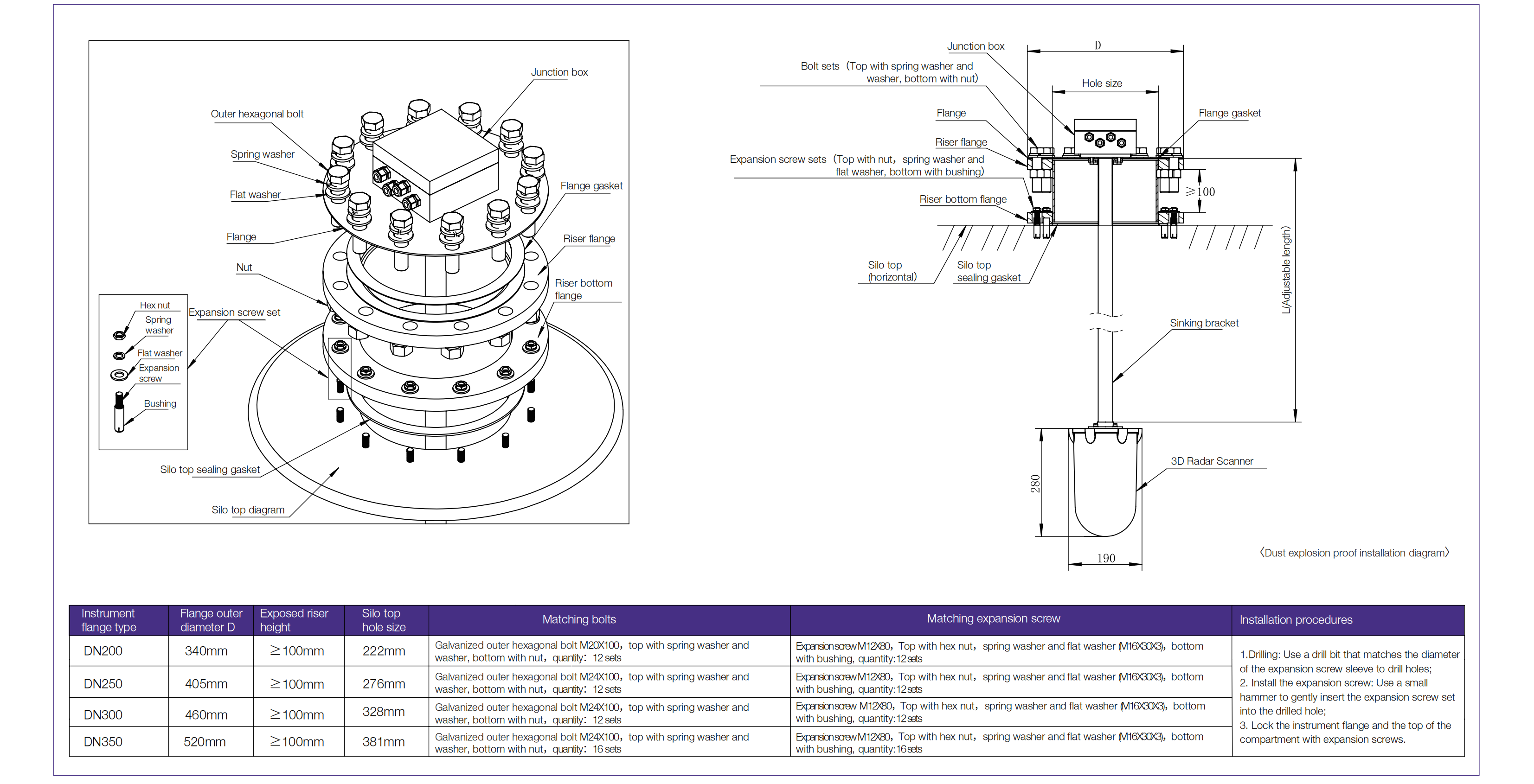
(3)The top of the flat silo is a steel plate structure/concrete structure, and after the opening of the silo top, it is directly installed and fixed with the
flange at the bottom of the riser through bolts.
Note: This installation method needs to consider the sealing problem between the flange at the bottom of the riser and the top of the silo.
The situation where the top of the silo is inclined
(1) The top of the inclined silo is a steel plate structure, and after the top of the silo is perforated, it is directly welded to the riser and installed and
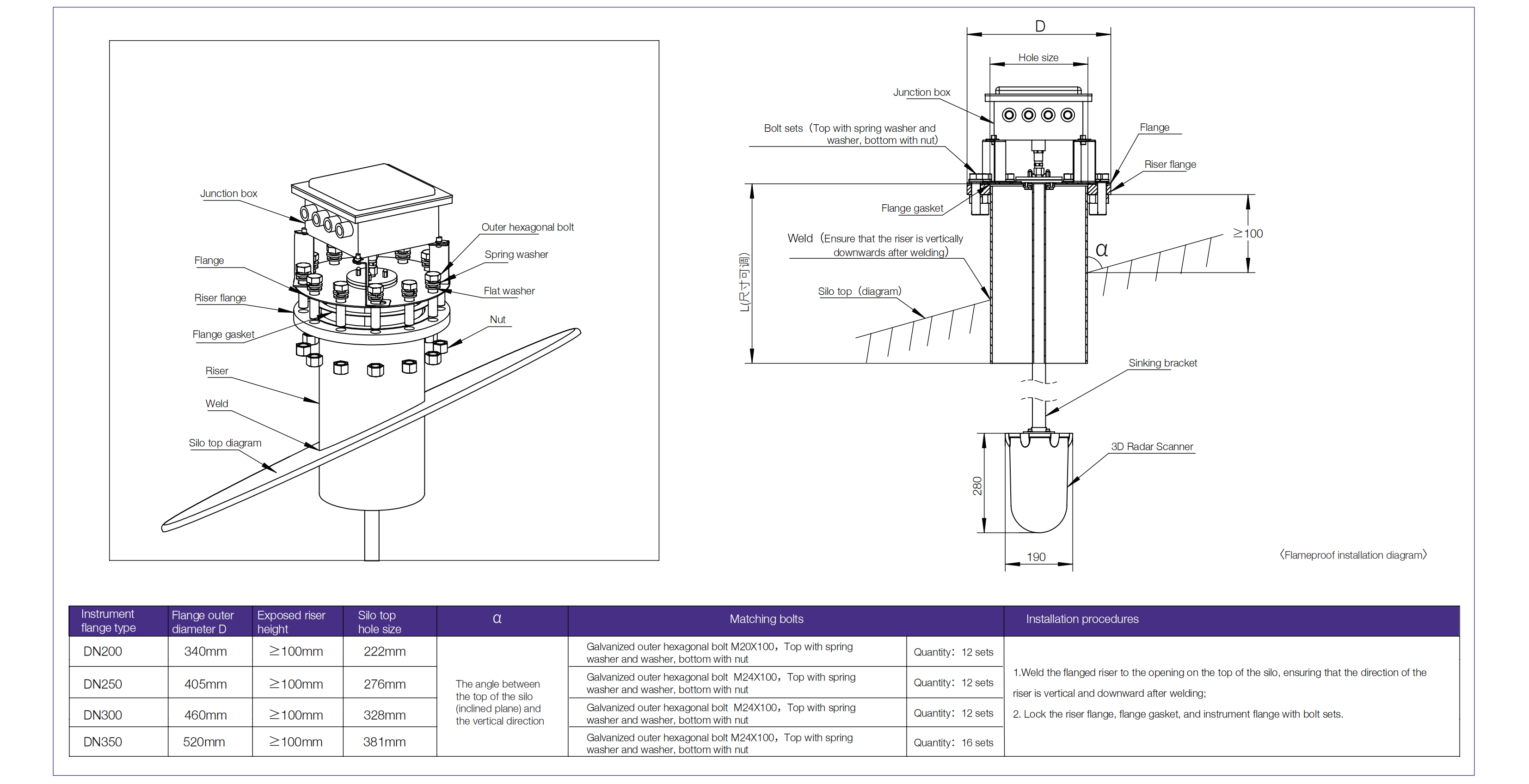
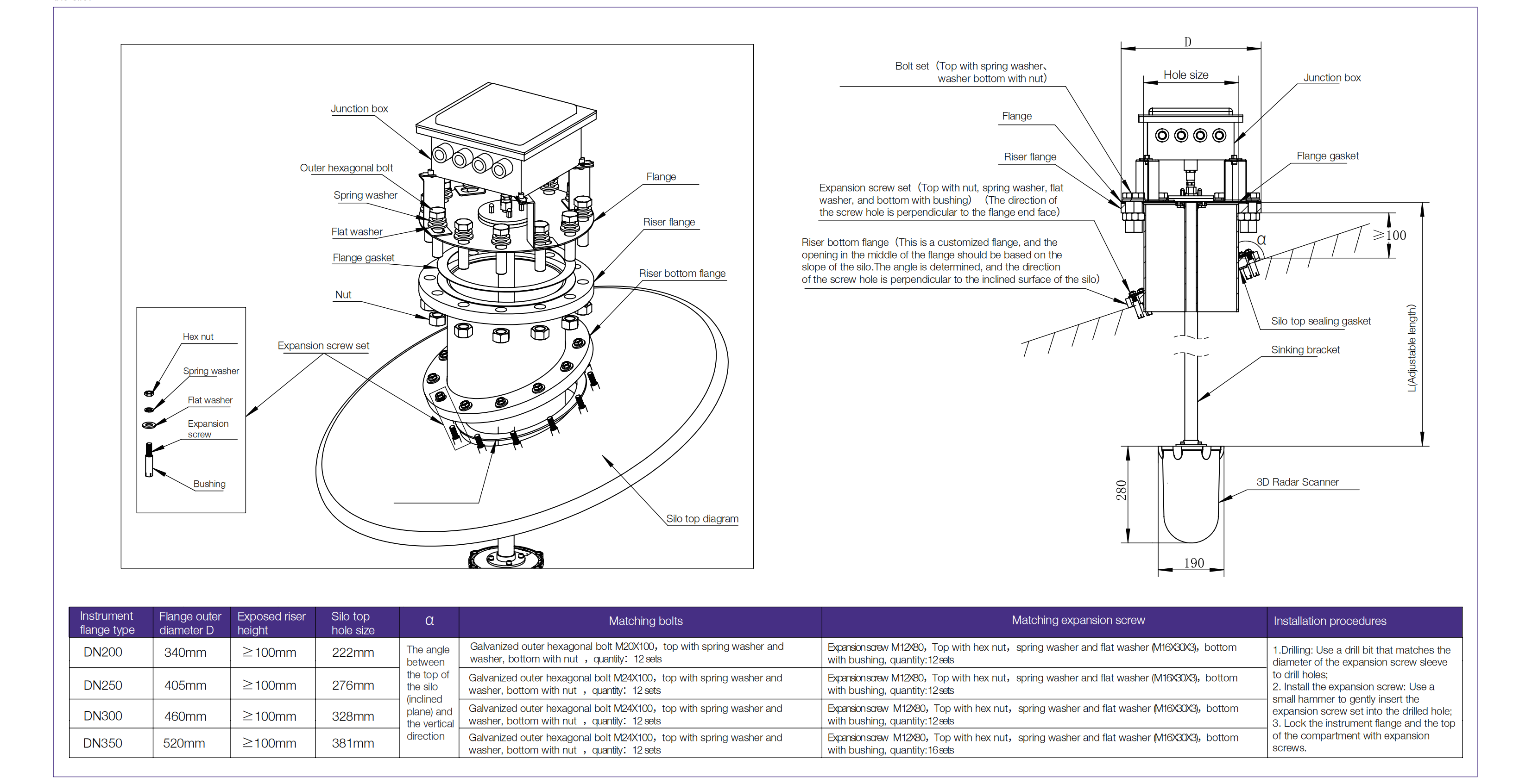
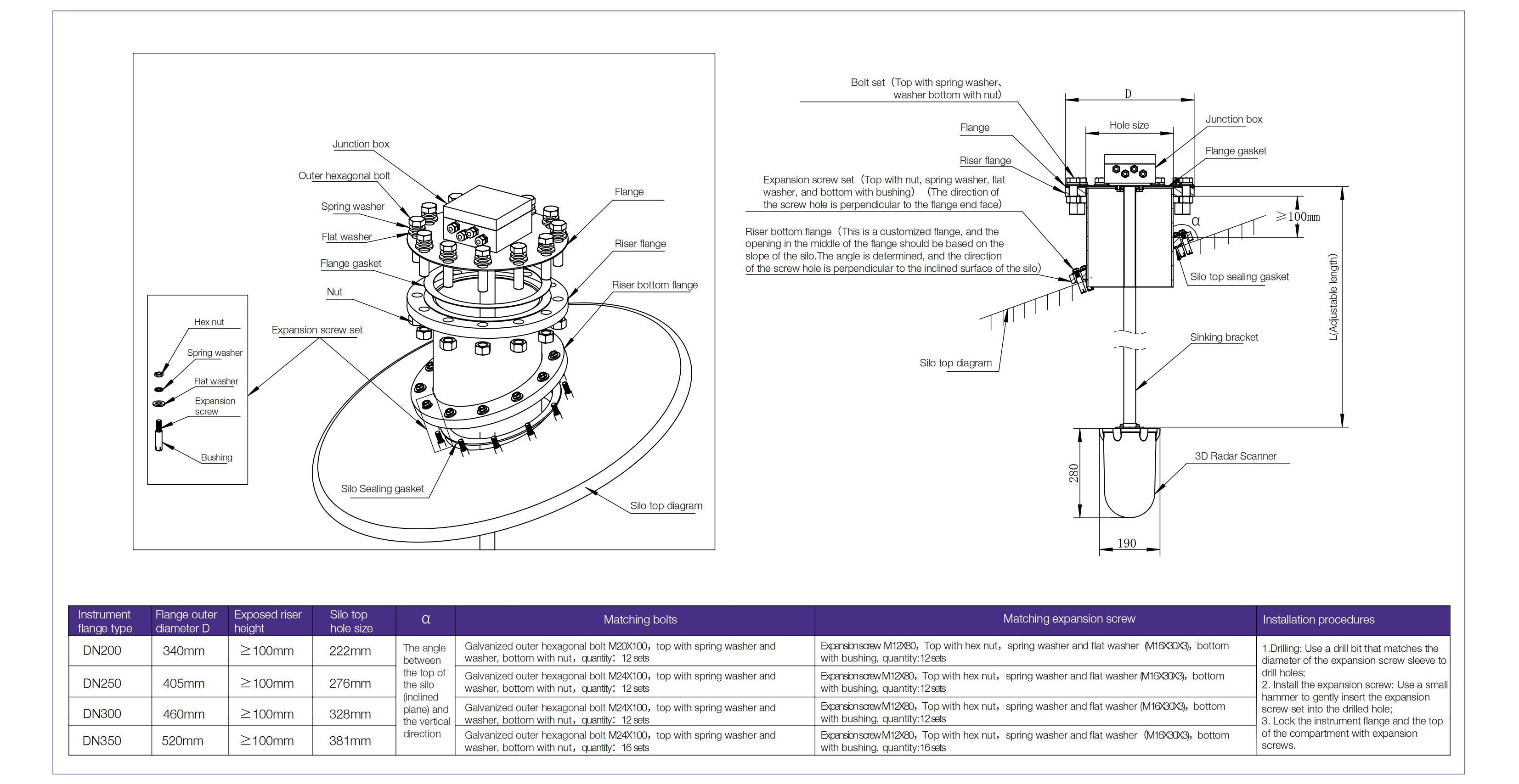
(2) The top of the inclined silo is a steel plate structure/concrete structure, and after the opening of the silo top, it is directly
installed and fixed with the flange at the bottom of the riser through bolts.
Note: This installation method needs to consider the sealing problem between the flange at the bottom of the riser and the top of the silo.
Installation instruction
▲The selection and length of sinking brackets depend on the structure and installation position of the silo. If there are obstacles such as crossbeams inside the silo at the installation position to avoid interference with the measurement signal, it is necessary to sink the radar scanner inside the silo to avoid obstacles such as crossbeams and improve the reliability and accuracy of detection. In addition, if there are no obstacles such as crossbeams inside the silo at theinstallation location, and the bottom of the radar scanner needs to be exposed to a depth of 20cm after installation, a sinking bracket can also be omitted.
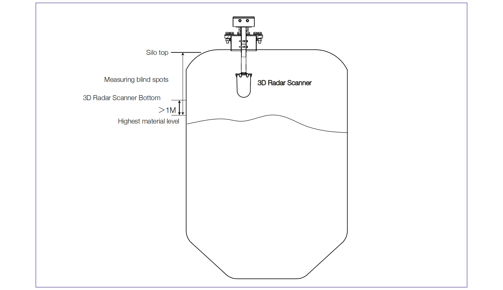
▲The radar scanner has a measurement blind spot, and materials cannot be detected after reaching the measurement blind spot. In severe cases, it can cause materials to flood the radar scanner and even overflow the warehouse. After installation, it is necessary to control the highest level that the material can reach during the feeding process (usually directly below the feeding port) to be lower than the bottom of the radar scanner. Moreover, due to the large angle of motion of the radar scanner in the pitch direction (greater than 45 °), the echo signal formed by the reflection of the measured signal after reaching the material surface cannot be well received, reducing measurement accuracy and even unable to measure. Therefore, the pitch scanning angle of the radar scanner is generally set to -45 ° to+45 °. Based on the relative position relationship between the installation position of the radar scanner and the feeding port, as well as the formation of solid materials, it is necessary to set the pitch scanning angle of the radar scanner. The resting angle pattern suggests that the distance between the highest material level and the bottom of the radar scanner should be greater than 1m. The closer the feeding port position is to the installation position of the radar scanner the greater the distance between the highest material level and the bottom of the radar scanner to ensure stable and reliable measurement.
System Framework
According to different on-site conditions, select the appropriate system framework, and the system diagram is listed as follows:
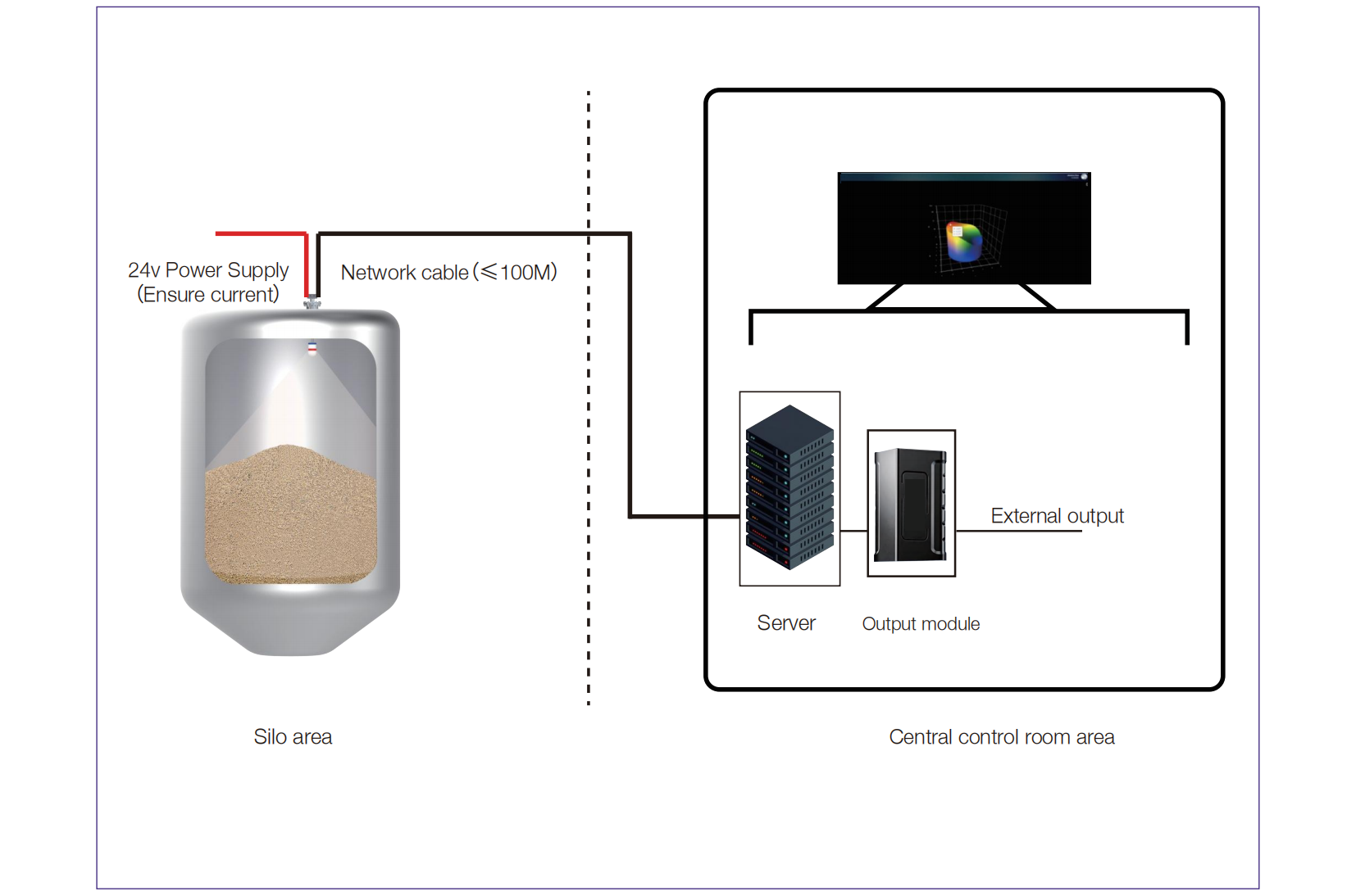
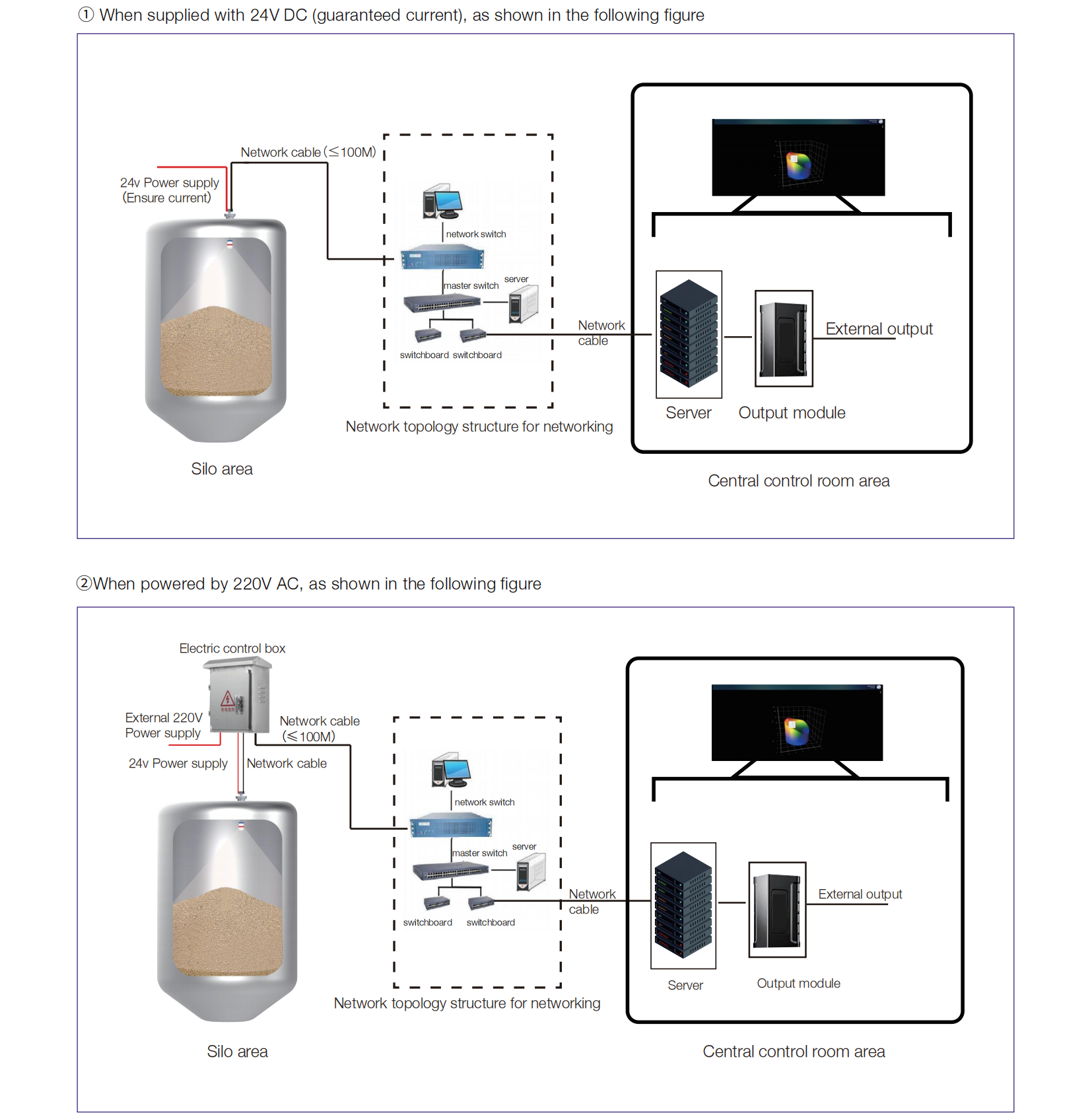
1、When providing a 24V DC voltage at the customer's site, it is necessary to ensure that the current is sufficiently large. The current value of each 24V DC voltage depends on how many 3D radar scanner the cable provides electricity to, meeting the current requirement of 0.5A for each 3D radar scanner. In addition, if the laying distance between the position of the 3D radar scanner installed on the top of the silo and the central control room server is less than 100M, the system diagram shown in the following figure can be selected.
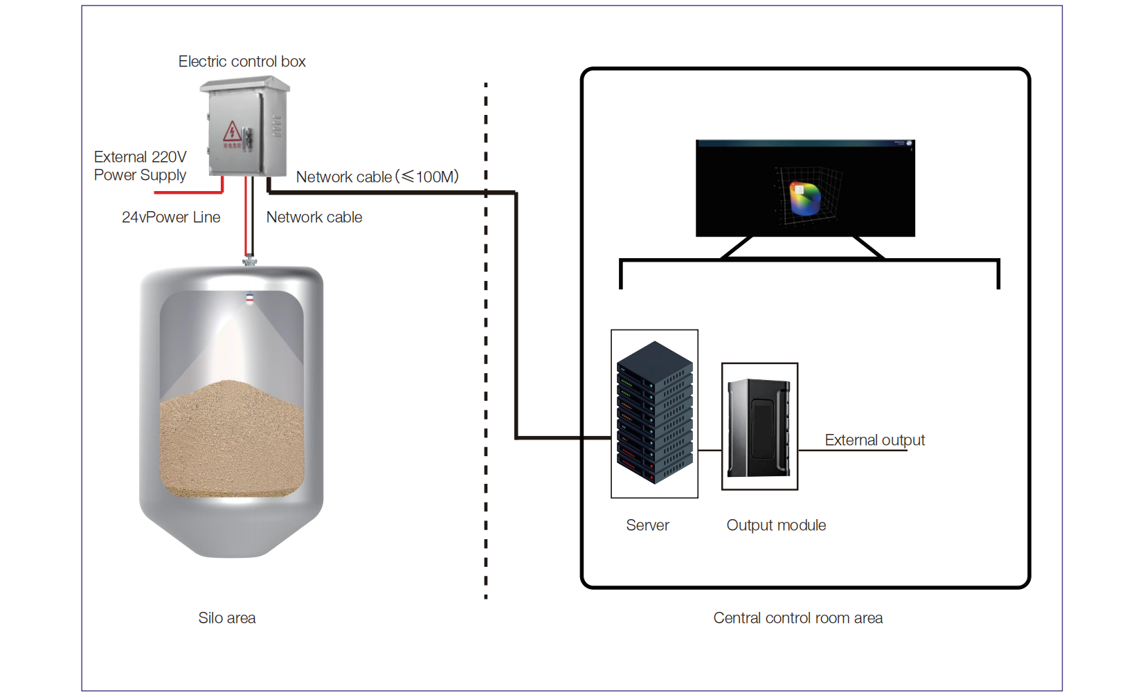
2、When providing 220VAC at the customer's site, an electrical control box must be installed at the top of the silo. The electrical control box is equipped with a power conversion module that converts 220VAC to 24VDC, providing electricity for the 3D radar scanner. In addition, if the laying distance between the position of the 3D radar scanner installed on the top of the silo and the central control room server is less than 100M, the system diagram shown in the following figure can be selected.
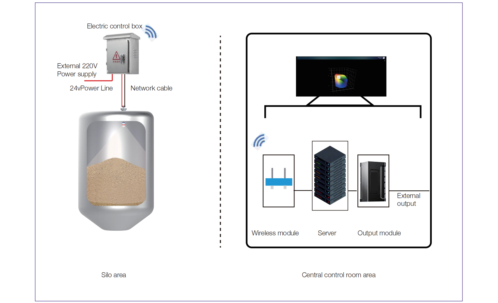
3、When providing 220VAC at the customer's site, an electrical control box must be installed at the top of the silo. The electrical control box is equipped with a power conversion module that converts 220VAC to 24VDC, providing electricity for the 3D radar scanning robot. The 3D radar scanning robot transmits the detected information to the electrical control box through a network cable. In the absence of acommunication cable between the top of the silo and the central control room, the electrical control box is equipped with a wireless module, which transmits the received detection information to the central control room through wireless (4G/5G). In addition, a wireless module is also installed next to the server in the central control room, After receiving the detection information transmitted wirelessly (4G/5G), the data is transmitted through a network cable connected to the server, as shown in the following figure.
4、When providing 220VAC at the customer's site, an electrical control box must be installed at the top of the silo. The electrical control box is equipped with a power conversion module that converts 220VAC to 24VDC, providing electricity for the 3D radar scanning robot. The 3D radar scanning robot transmits the detected information to the electrical control box through a network cable. The electrical control box is equipped with a photoelectric conversion module, which converts the network signal into an electrical signal and transmits it to the central control room through optical fibers, In addition, there is also a photoelectric conversion module installed next to the server in the central control room, which receives optical signals transmitted by optical fibers and converts them into network port signals. The data is transmitted to the server through network cables, as shown in the following figure.
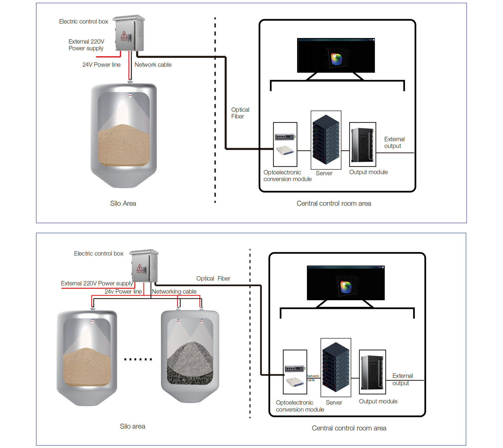
5、The on-site customer has designed and laid a network topology structure between the top of the silo and the central control room, which is used for transmitting detection information from the top of the silo to the central control room. Both ends of the network topology structure are RJ45 network interfaces.
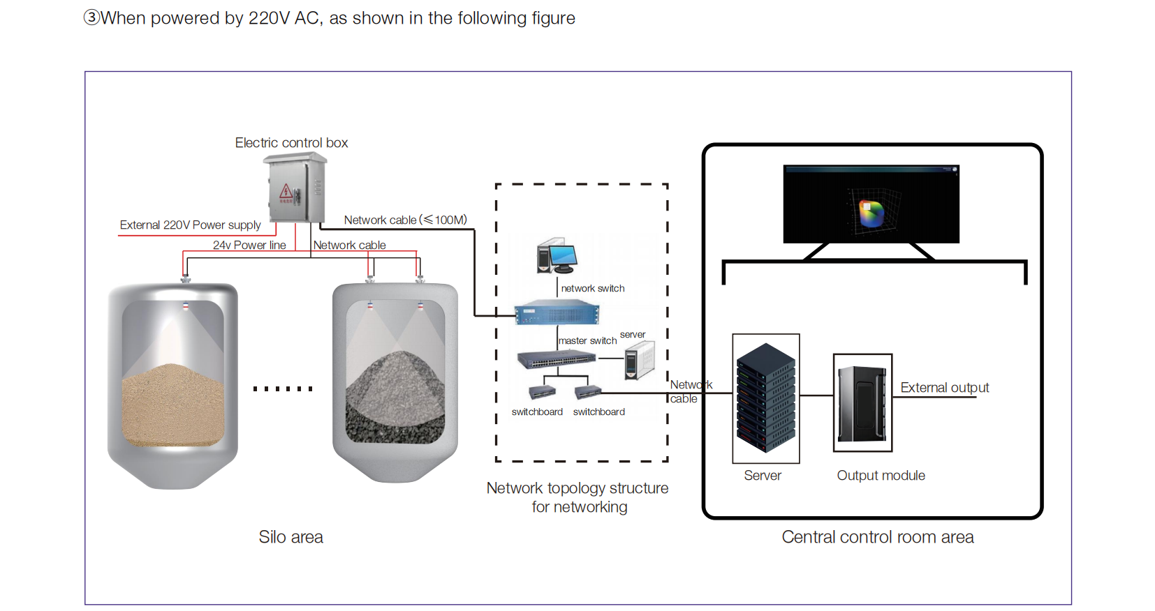
Output Module Description: The 3D radar scanner transmits the detected information to the server, which performs calculations, processing, and analysis. Finally, the 3D diagram and material parameters related information are presented on the ProInventory upper computer interface. If the customer's other control systems on site have the need to receive specific data to participate in linkage control or information integration, the output module illustrated in the system diagram above can be optionally equipped, The type and quantity of output modules depend on the communication methods and material parameters required by other control systems on the customer's site. The customer needs to provide the manufacturer with the communication methods and material parameters required by their control system, and the manufacturer will adapt suitable output modules.
Product Size
kaidi 3DPro2300 product structural size (Note: The values marked in [] are in inches, the rest are in millimeters)
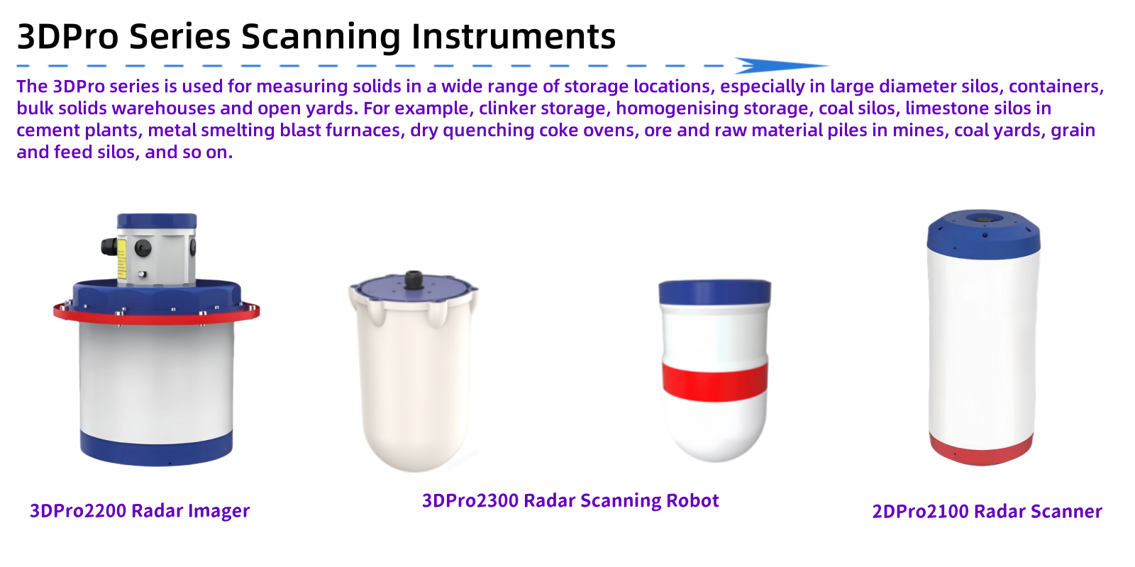
Related Products
We are here to help you! If you close the chatbox, you will automatically receive a response from us via email. Please be sure to leave your contact details so that we can better assist